Modeling & Editing
Learn about some of the improvements when modeling & editing in Rhino 9.
ScaleEach
- Download Rhino 9 Evaluation for Windows or Mac.
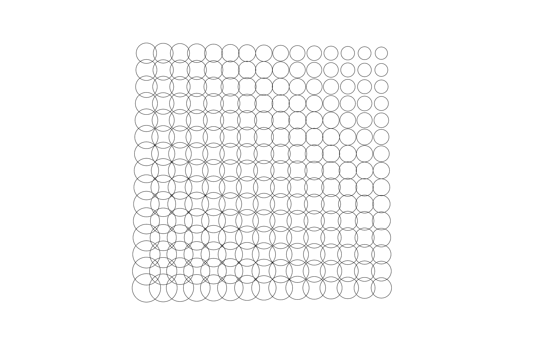
- Download and open the ScaleEach-Array.3dm model. You’ll find an array of 15 x 15 circles.
- Run the
 ScaleEach
command.
- Select all the circles.
- Select
Factorin the Command Prompt , set it toGradient. - Drag the slider’s handle to reposition it on the array of circles.
- Adjust the sliders’ values.
- Press Enter or the Space bar to complete the command and confirm the result.
- Try it on your own! Experiment with the other scale styles, uniform, selection order, random, gradient, and attractor.
- Share comments and feedback on the Rhino Forum.
ArrayCrv
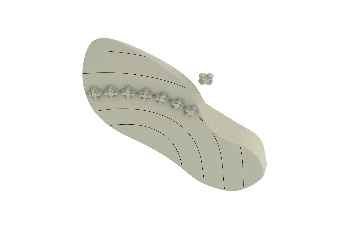
- Download Rhino 9 Evaluation for Windows or Mac.
- Download and open the Try_ArrayCrv.3dm model. This file includes a sneaker sole model and tread pattern object.
- Run the
 ArrayCrv
command.
- Right-click or press Enter twice to open the ArrayCrv dialog.
- In the Curve Selection section of the ArrayCrv dialog, select
Select Curve. - Select a curve on the sneaker sole. The ArrayCrv dialog will reappear.
- In the Object Selection section of the ArrayCrv dialog, select
Select Objects. - Select the tread pattern object to the side of the sole. Press Enter. The ArrayCrv dialog will reappear.
- In the Curve Selection section:
- Deselect
On Ends. The objects centered at the ends of the curve will move inward. - Drag the
Span Rangevalue handles to change where the first and last arrayed object is located on the curve. Alternatively, use the in-viewport widgets to adjust.
- Deselect
- In the Orientation section:
- Select the Orientation Object icon in the
Orientation Directionsetting. - Select the sneaker sole surface to force the array’s orientation to its surface normal direction.
- Change the
Vertical Alignsetting toBottom.
- Select the Orientation Object icon in the
- In the Transform Adjustments section, set the
N offsetvalue to -.02. It will sink the tread pattern objects slightly into the sneaker sole. - Try it on your own! Experiment with your favorite models.
- Share comments and feedback on the Rhino Forum.
InflateCrv
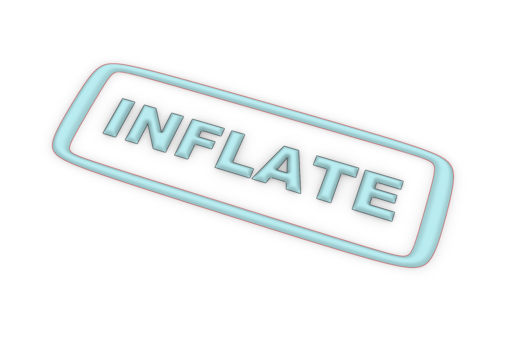
- Download Rhino 9 Evaluation for Windows or Mac.
- Download and open the InflateCrv-Example.3dm model.
- Run the
 InflateCrv
command.
- Window select the curves and press Enter.
- In the
Command Prompt
, set the:
Heightto 5. Press Enter.Flattenningto 0.2. Press Enter.- Select the
Flipoption to change the direction of the geometry if need be. - Set
Quad RemeshtoYes. - Set
OutputtoSubD. - Press Enter to end the command.
- Try it on your own! Experiment with your own examples.
- Please provide feedback or ask questions on the Rhino Forum.
SoftTransform
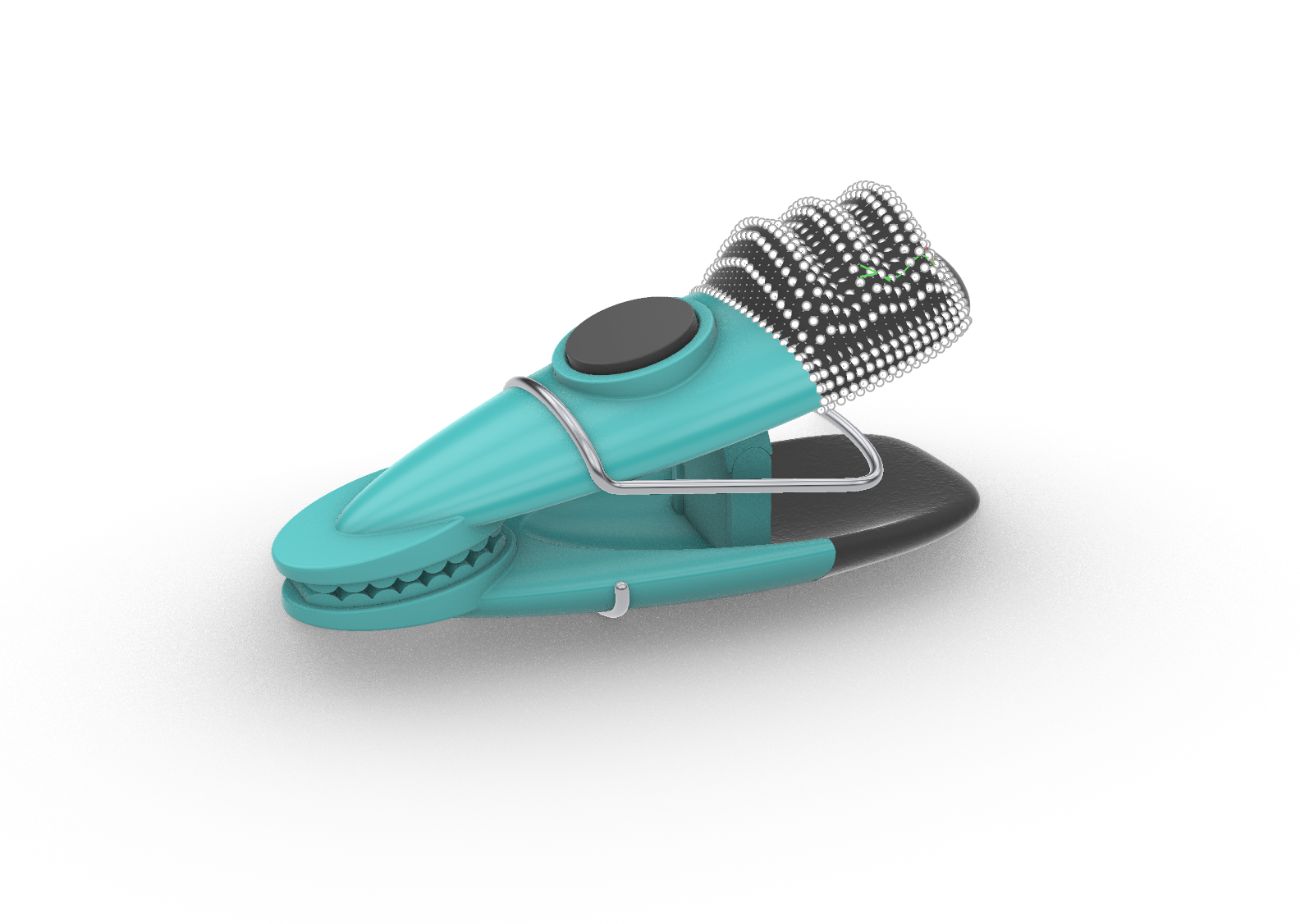
- Download Rhino 9 Evaluation for Windows or Mac.
- Download and open the soft-transform-demo.3dm model. You’ll find a clip with a rubber grip.
- Open the NamedSelections and SoftTransform panels (Window menu: Panels).
- Double-click the grip points in the NamedSelection panel:
- Click the Enabled button in the SoftTransform panel:
- In the panel, set:
- Set the Distance Measure to Along Object
- Set the Shape to Round
- Set the Count U to 10
- Gumball Move the points in the Z direction to create the surface grip.
- Try it on your own! Experiment with different falloff shapes or by using the Radius slider when the measure is set to Spherical.


Gumball: Control Polygon
- Download Rhino 9 Evaluation for Windows or Mac.
- Download and open UVN_Gumball_TryIt.3dm in Rhino.
- Window-select all the surfaces.
- With the surfaces selected, run the
 Zebra
command. It opens an analysis panel that displays stripes to understand surface continuity:
- Enable
Show wires - Set the
Backgroundcolor toGray.
- Enable
- Run the
 GlobalEdgeContinuity
command. It opens an analysis tool that displays edge deviation between surfaces.
- Select the surfaces again.
- Run the
 PointsOn
command to turn on their
Control Points
.
- Activate the Gumball in the Status Bar .
- In the Status Bar , right-click Gumball (CPlane) and select Align to Object.
- Select a control point in the middle surface. The Gumball arrows are aligned to the control point’s U, V and N (Normal) direction.
- Drag any Gumball arrow: it stays constrained to move along the U, V, or N axis. Watch the Zebra analysis and the GlobalEdgeContinuity statistics update dynamically in real time.
- Try it on your own! Experiment with your own models.
- Share comments and feedback on the Rhino Forum.
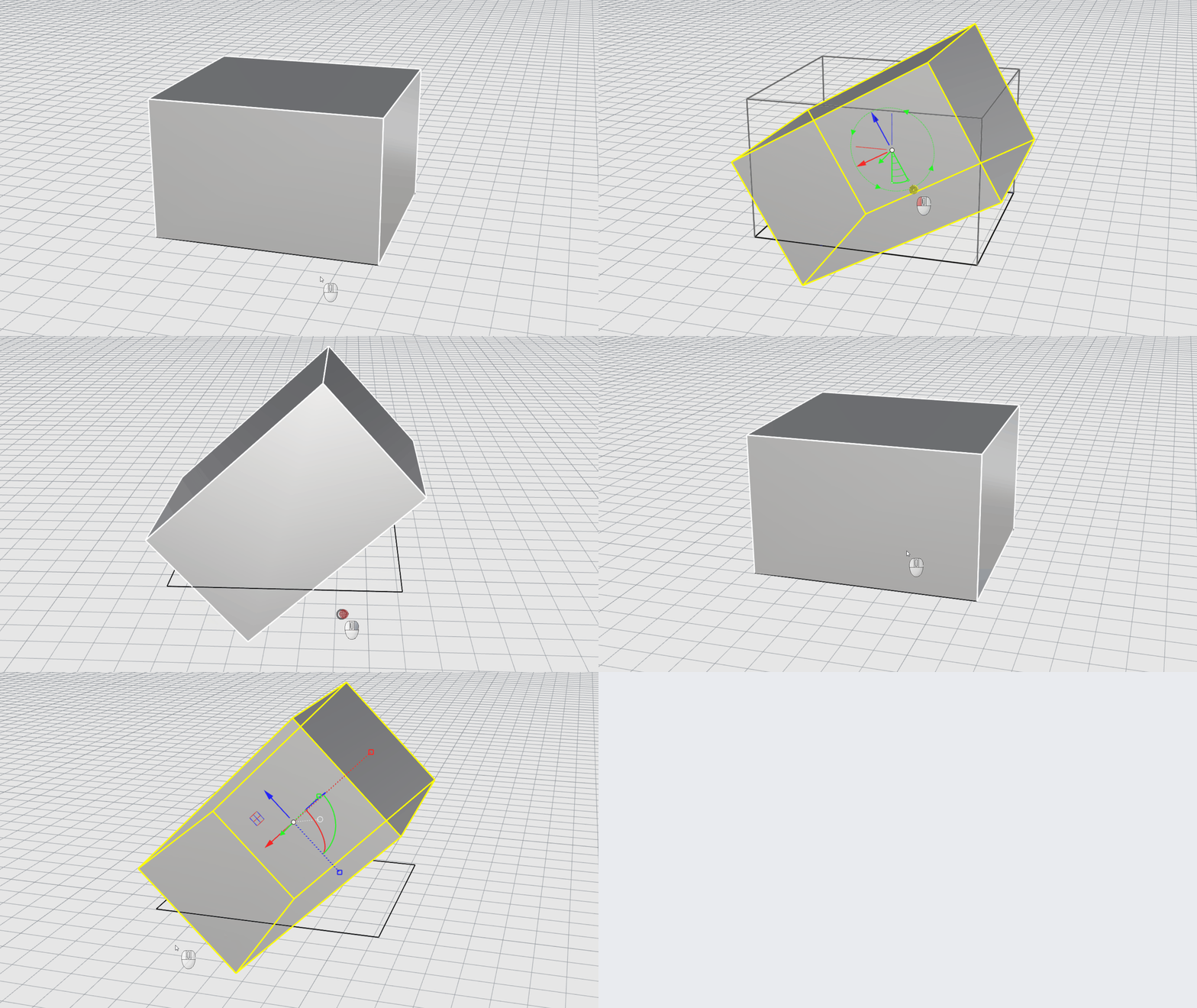
Gumball: Rotate-Extend
In this exercise, try the  Gumball
Rotate-Extend mode.
- Download Rhino 9 Evaluation for Windows or Mac.
- Download gumball-rotate-extend.3dm in Rhino .
- Activate the Gumball .
- Sub-Object Select one of the vertical faces.
- Hold down + while dragging the Gumball Rotate handle. Then, let go.
- The face has been rotated while adjacent faces extend without deforming!
- Try it on your own! Experiment with your own models.
- Share comments and feedback on the Rhino Forum.
Inset: Shaping Detail
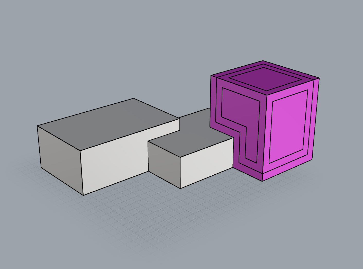
- Download Rhino 9 Evaluation for Windows or Mac.
- Download and open inset-multiface.3dm.
- Run the
 Inset
command.
- At the
Select faces and ngonsprompt , select the 3 magenta surfaces. Press Enter. - At the
Inset Distanceprompt, type 10 and press Enter. - Select the Mode option in the prompt and set it to:
Mode=Group. - You get a single loop that crosses all three faces! You can
 PushPull
or make other changes that run across the object.
 Undo
the changes and run the Inset
command again, this time with
Mode=Singleto see the difference.- Try it on your own! Experiment with your own models.
- Share comments and feedback on the Rhino Forum.
PushPull
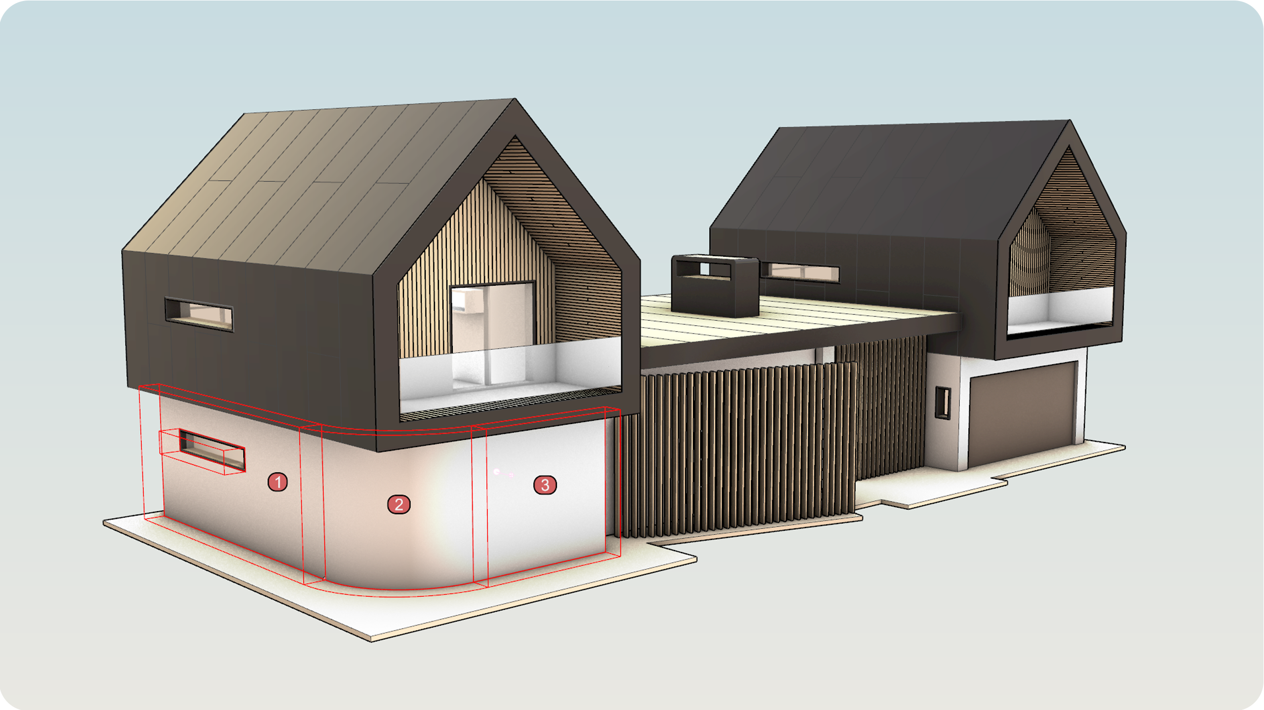
- Download Rhino 9 Evaluation for Windows or Mac.
- Download and open the MultiSrf_PushPull_Arch_TryIt.3dm model.
- Run the PushPull
command.
- At the
Select surfaces to PushPullprompt , select the walls marked 1, 2 and 3. Press Enter to confirm. - At the
PushPull distanceprompt, drag your mouse outward to define the direction. Type 500 for the distance. - You have now modified multiple connected surfaces without rebuilding the model!
- Try it on your own! Experiment with your own models.
- Please ask questions or give feedback on the Rhino Forum.
Patch
- Download Rhino 9 Evaluation for Windows or Mac.
- Download and open the hairdryer.3dm model.
- Run the
 OneLayerOn
command and select layer base-surfaces.
- Change your working viewport’s display mode to Shaded .
- Run the
 Patch
command.
- Click on the edges surrounding the hole you want to fill. Each edge will be marked with a G1 dot, indicating that tangency continuity is set for this edge.
- Click once on the top dot. It will be changed to a G2 dot. Patch will then try to make the surface curvature continuous at this edge.
- Press . The Patch dialog will show up.
- Check preview to enable the (pink) preview. Notice the Constraints test results at the bottom of the dialog turn red.
- Check refine to let Patch refine the surface. Notice the Constraints test results turn green.
- Press to create the Patch.
- Try this on your own surfaces. Please ask questions and give feedback on the Discourse Forum.
Fillet and Blend Edge
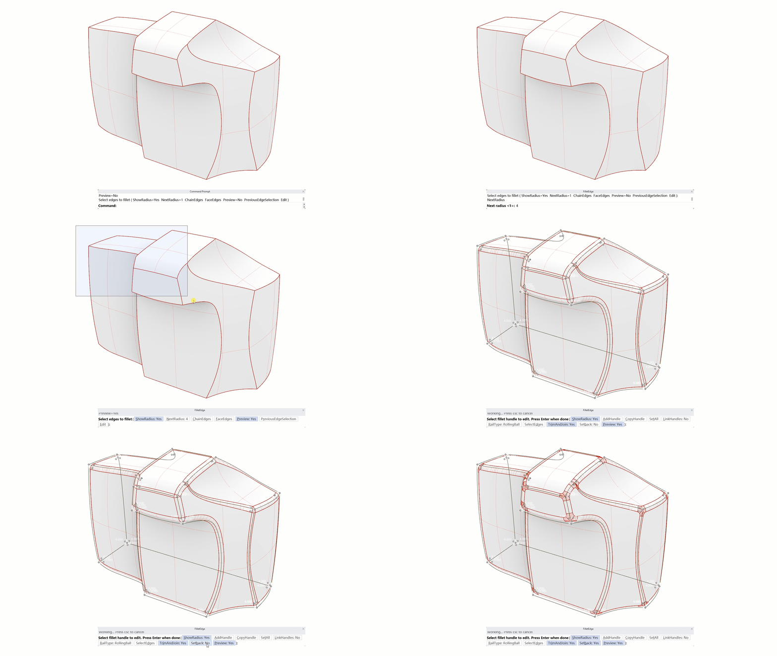
- Download Rhino 9 Evaluation for Windows or Mac.
- Download and open the FilletEdge_Setback.3dm model.
- Run the command
 FilletEdge
.
- In the
Command prompt
, select
NextRadius. - At the
NextRadiusprompt, type 4. Press Enter. - Select
Previewto set toYes. - Window select the entire camera model to select all edges. Press Enter.
- Zoom-in to one of the corners of the camera. Notice that a triangular surface has been created for each corner.
- In the
prompt
, select
Setbackto set toYes. Now, all the triangular surfaces have been replaced with 4-sided multiblend transitions. - Press Enter to complete the command.
- Try it on your own! Experiment with your own models.
- Share comments and feedback on the Rhino Forum.
Surface Fillets
- Download Rhino 9 Evaluation for Windows or Mac.
- Download and open the filletsrf_chains.3dm model.
- Run the command
 FilletSrf
.
- At the
Select first surface to filletprompt , select the orange surface. - At the
Select second surface to filletprompt, select the wavy pink surface. - The FilletSrf dialog appears:
- Select the Continue across faces option.
- Select the Trim and Join options.
- Set a radius by moving the slider or double-clicking to type a value (3mm to 15mm).
- Press OK to close the dialog.
- Ask questions and give feedback on the Discourse Forum.
Rebuild
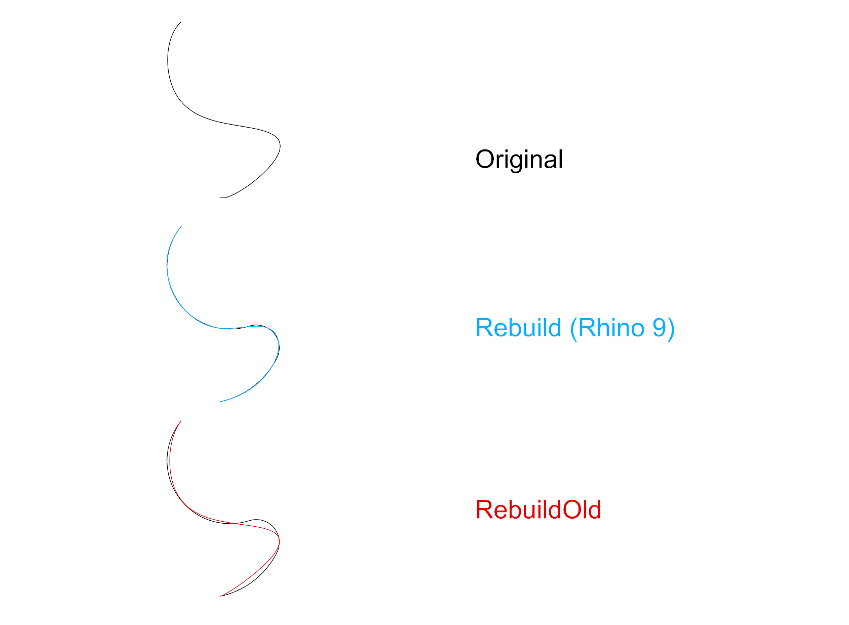
- Download Rhino 9 Evaluation for Windows or Mac.
- Download and open the rebuild-ex2.3dm model.
- Select the curve named Original.
- Run the
 Rebuild
command.
- In the Rebuild dialog:
- Select
Rebuild by point count. - Set
Point countto 7. - Set
Degreeto 5. - The
Max Deviationis around 0.1. - Select the
Cancelbutton.
- Select
- Now, run the
 RebuildOld
and press Enter.
- Follow steps 2 & 3 above.
- The
Max Deviationis around 1.2.
- Try it on your own! Experiment with your own models.
- Share comments and feedback on the Rhino Forum.
MatchSubD
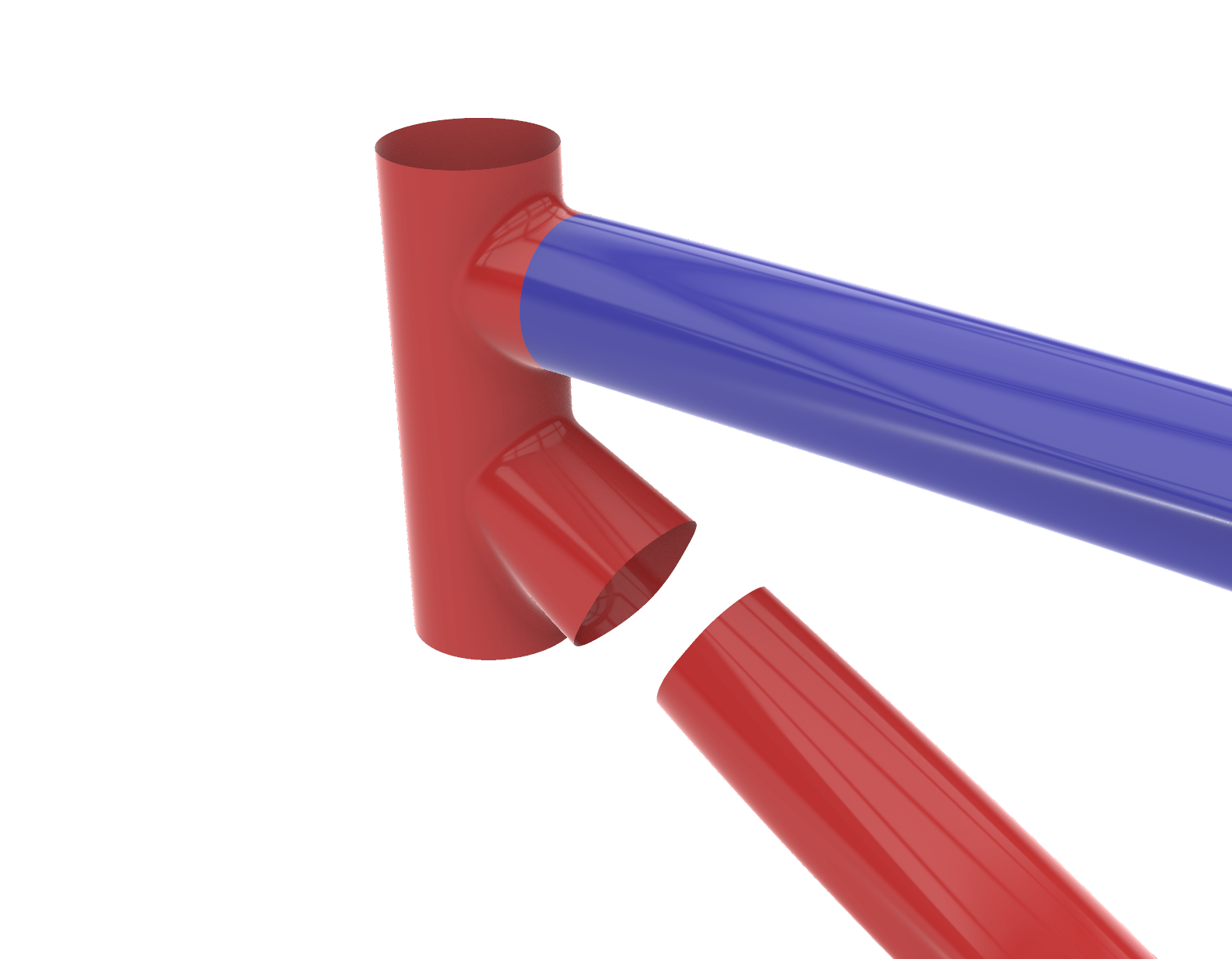
- Download Rhino 9 Evaluation for Windows or Mac.
- Download and open the matchsubd.3dm model.
- Run the
 MatchSubD
command.
- At the
Select a chain of SubD boundary edgesprompt , sub-object select the open boundary edge on the blue tube. - Press Enter.
- At the
Select a chain of boundary curves to matchprompt , sub-object select the adjacent open boundary edge on the red head tube. - Press Enter.
- In the Command Prompt , select MatchTangents.
- Drag the tangent widget to adjust the match.
- Press Enter when done.
- Try it on your own! Experiment with your own models.
- Share comments and feedback on the Rhino Forum.
Knife
- Download Rhino 9 Evaluation for Windows or Mac.
- Download and open the SubDKnife-Example.3dm file.
- Run the
 Knife
command.
- At the
Select mesh or SubDprompt , select Subd 1. - At the
Select first knife pointprompt, select a few points on the left side faces. - Press Enter when done.
- Repeat steps 3. through 6. until you get all the desired “cuts”.
- Run the
 ExtrudeSubD
to extrude the new faces created.
- Try it on your own! Experiment with your own models.
- Share comments and feedback on the Rhino Forum.
Inset Multiface
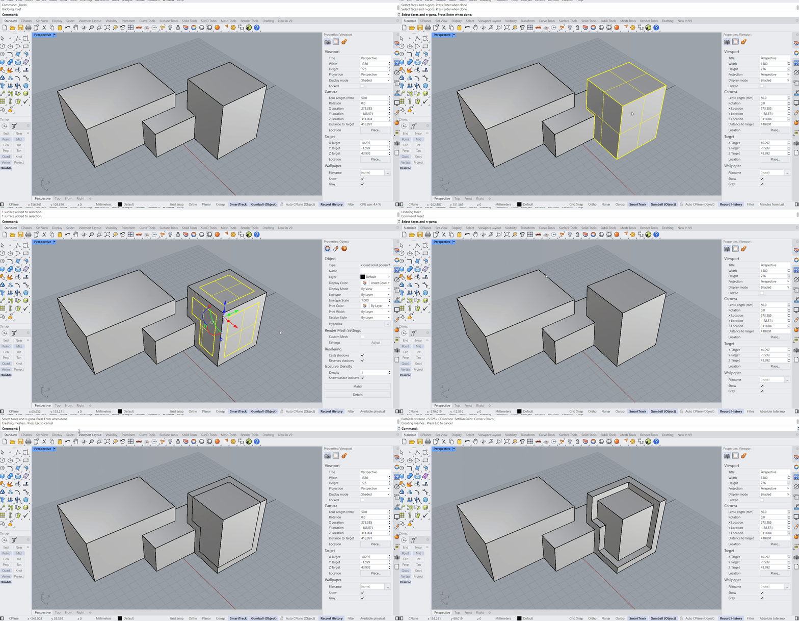
Inset now supports grouping faces. This accelerates the solid editing process and is very helpful when multiple faces of a polysurface need to be pushed-pull or extruded as a continuous element.
- Download inset-multiface.3dm.
- Run the Inset
command.
- Select 3 surfaces adjacent surfaces and press .
- Select the Mode option in the
prompt
. It should read:
Mode=Group. - At the Inset Distance prompt , type 10 and press .
- You get a single loop that crosses all three faces!
PushPull Multiface
Rhino’s PushPull
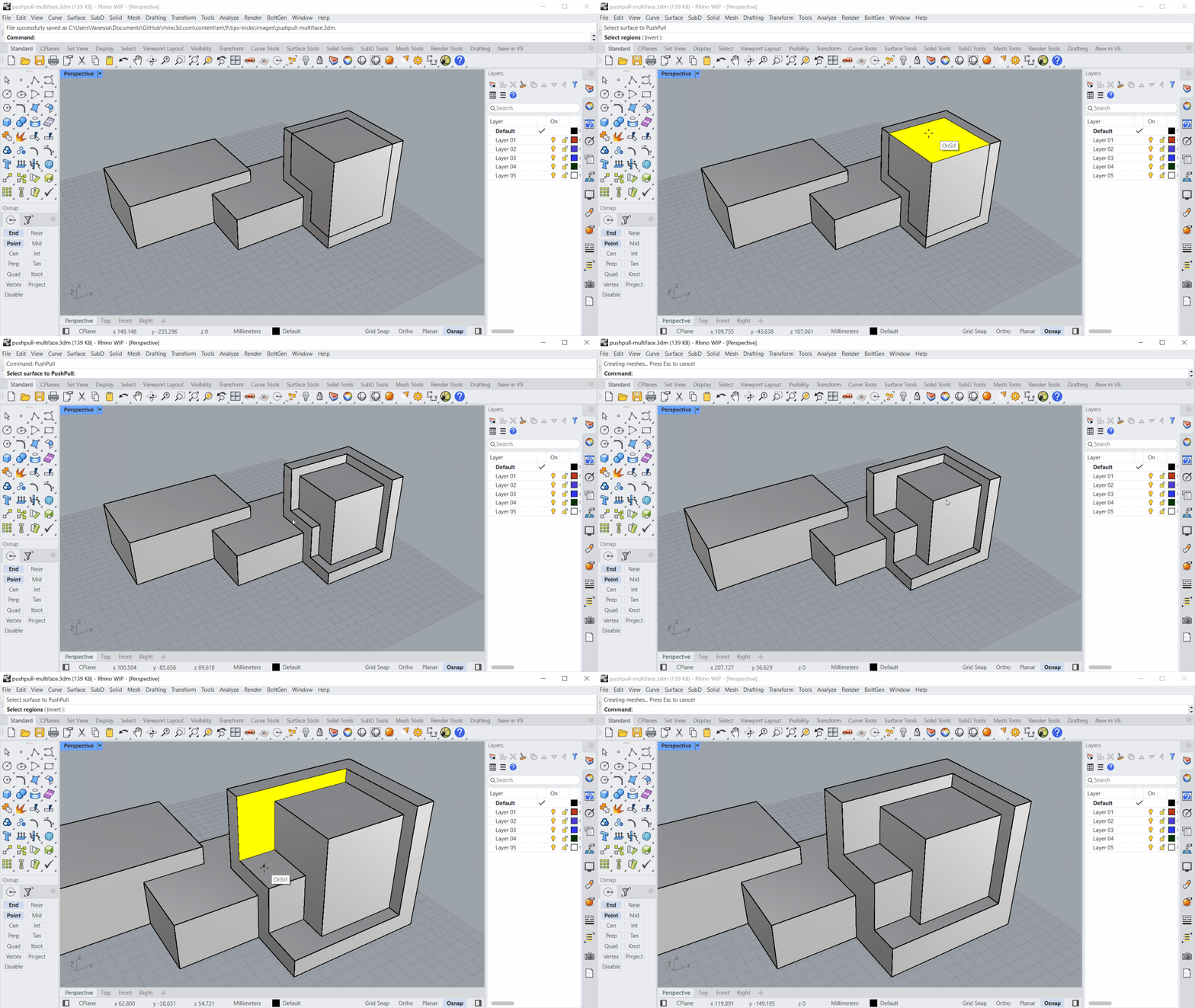
command now supports selecting multiple faces in one go. This is helpful
- Download pushpull-multiface.3dm.
- Run the PushPull
command.
- At the Select surface to PushPull prompt , select multiple surfaces and press .
- At the PushPull distance prompt, drag your mouse or enter a numerical value.
- Keep playing!
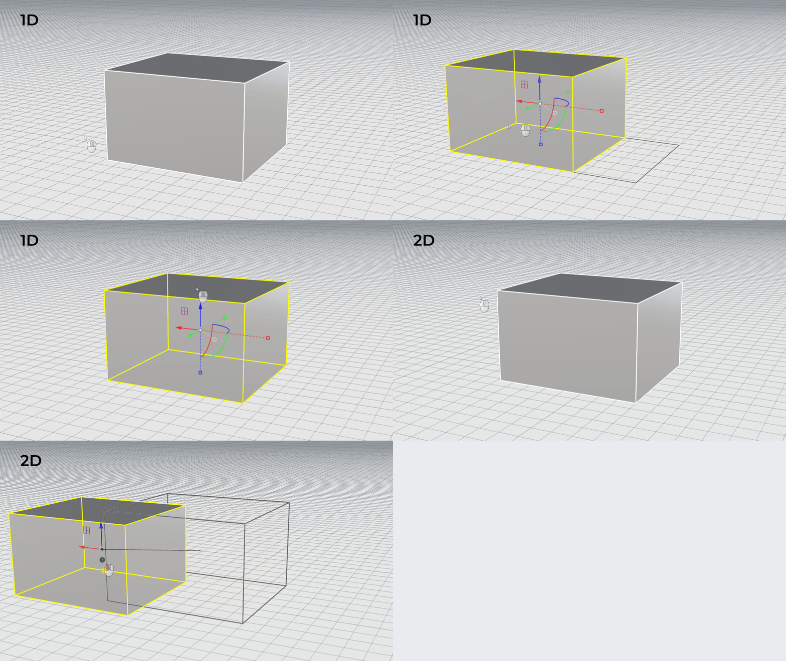
Gumball Rotate-Extend
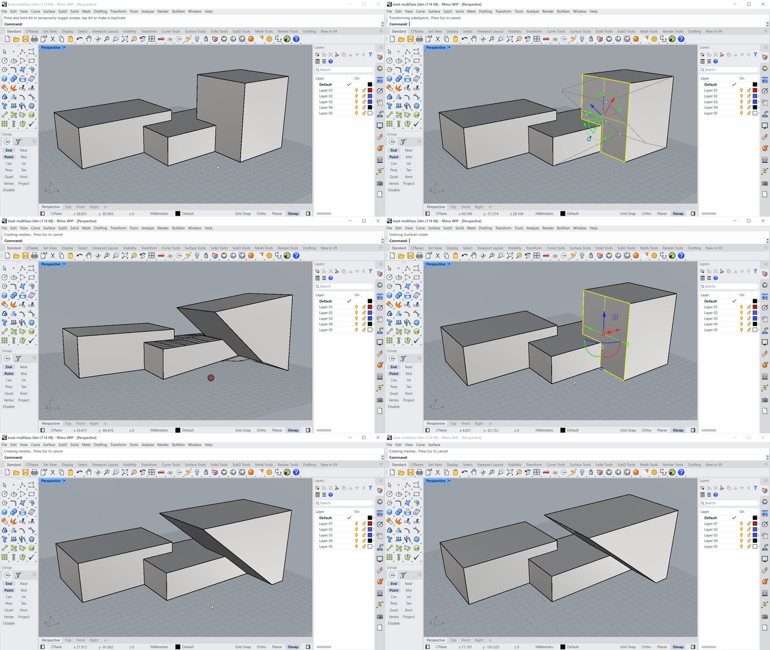
You can now use the Gumball Rotate handle to shear a face while in rotation. This avoids deforming adjacent faces.
- Download gumball-rotate-extend.3dm.
- Activate the Gumball .
- Sub-object select one of the vertical faces.
- Hold down + while dragging the Gumball Rotate handle.
- Your face is sheared!
Explode: TangentComponents
The  Explode
command allows you to extract surfaces with a tangent connection as a single part. This is great for extracting parts that need to be shelled or given another wall thickness.
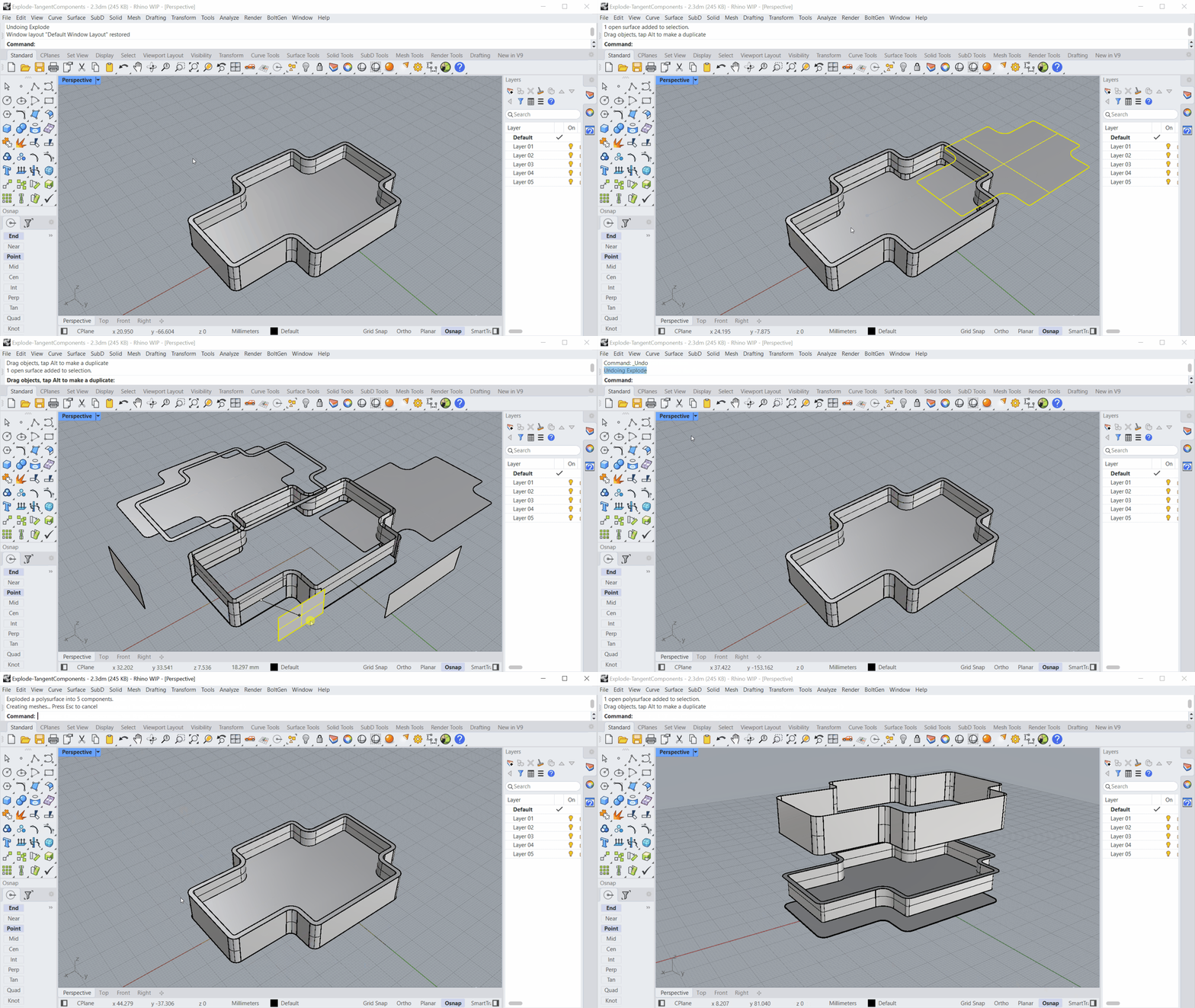
- Download explode-tangentcomponents.3dm.
- select the polysurface.
- Run the Explode
command.
- At the Press enter to accept
prompt
, make sure:
TangentComponents=Yes. - Press twice to end the command.
- Your tangent surfaces have been extracted as a single part!
Fillets | Chamfers
Learn about the improvements to surface connecting commands, such as FilletSrf
,  FilletSrfToRail
or
 ChamferEdge
amongst others.
FilletSrf
FilletSrf in Rhino 8 and earlier only allows connecting one surface pair at a time, making the process of filleting a
Polysurface
very time consuming. In Rhino 9, FilletSrf
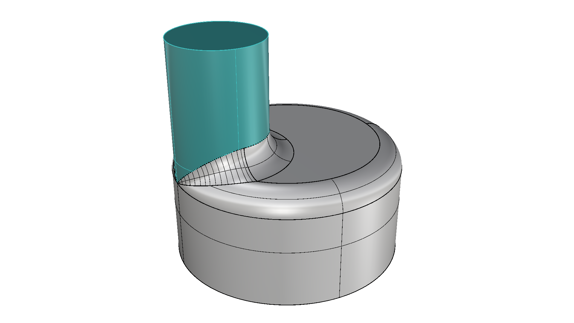
includes an option named Continue across faces. Create a chain of tangent fillet surfaces across your product in one go!
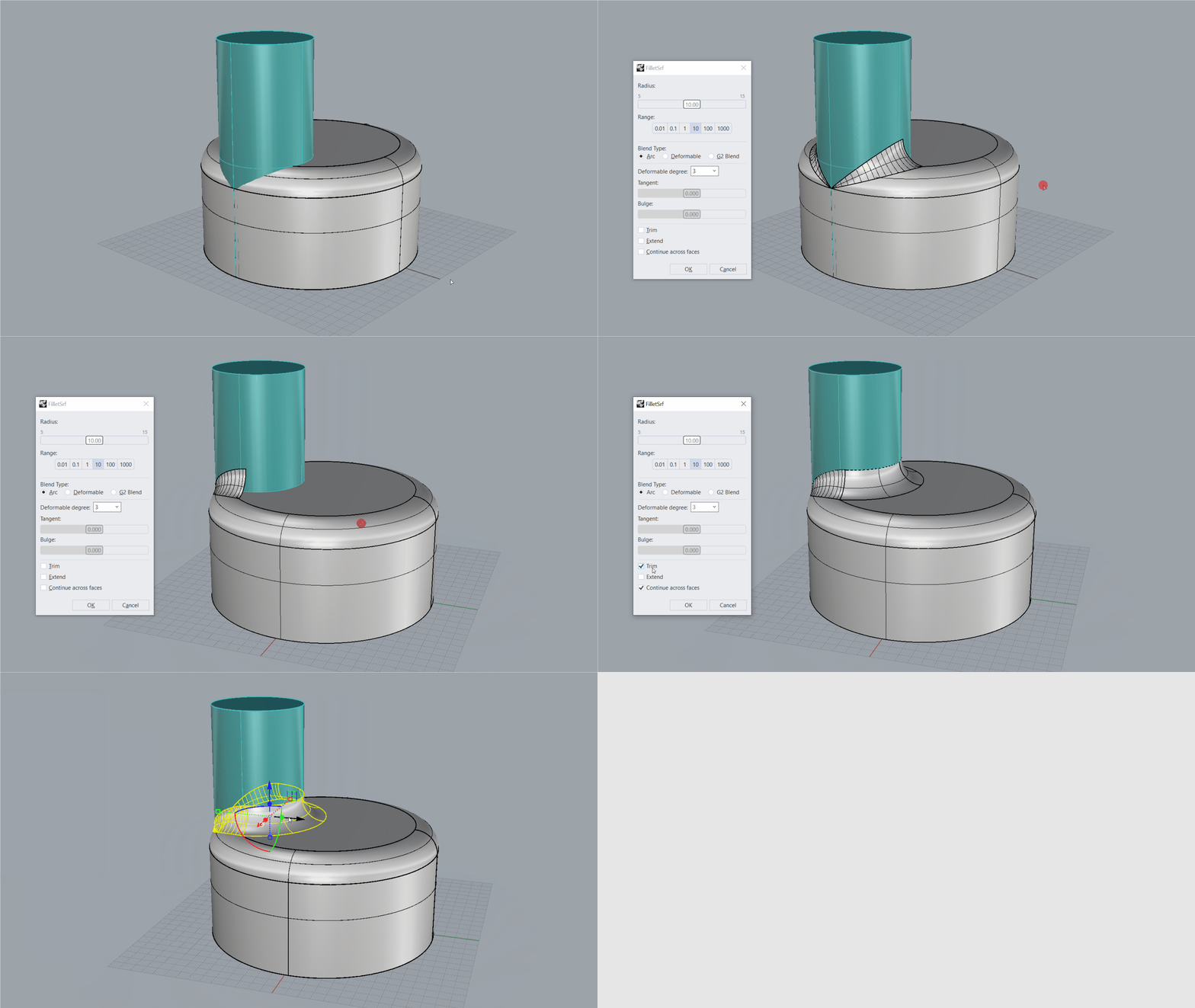
- Download filletsrf-extend.3dm.
- Run the FilletSrf
command.
- At the Select first surface to fillet prompt , select the fillet surface on the grey cylinder.
- At the Select second surface to fillet prompt , select the turquoise cylinder.
- In the FilletSrf dialog, select Trim and Continue across faces.
- Press OK to close the dialog.
- The result is filleted along all faces and trimmed!
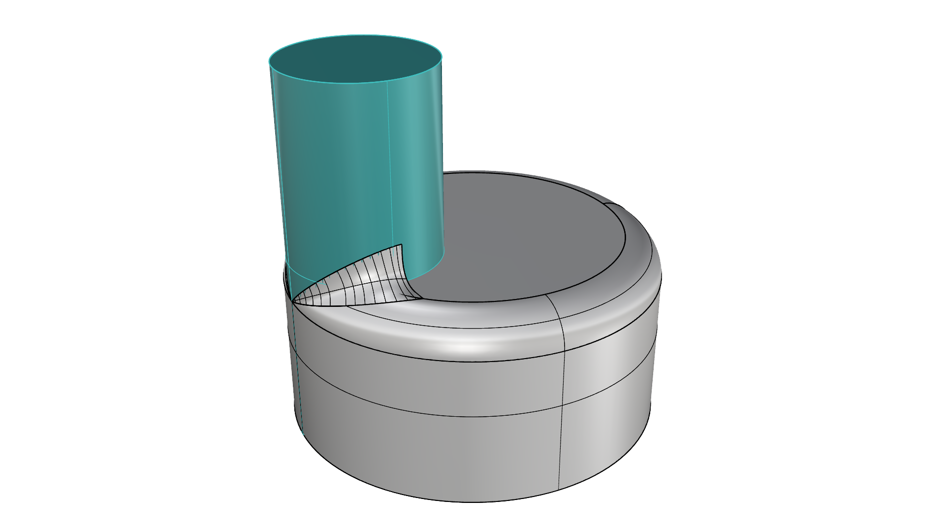
Rhino 8
Rhino 9
Learn about the new features and enhancements to the SubD toolset in Rhino 9.
MatchSubD
The MatchSubD
is new to Rhino 9. It allows you match a SubD chain of edges to another boundary. This boundary can be a curve, a
surface
edge or another
SubD
edge chain. You can also make the SubD tangent to the target object, if it’s a surface or SubD. This is useful when matching a SubD to other objects or shapes that have manufacturing constraints, such as a certain radius.
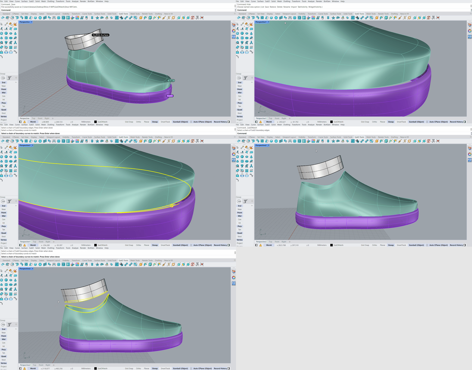
- Download subdmatch.3dm.
- Run the MatchSubD
command.
- At the Select a chain of SubD boundary edges prompt , double-click on the edge representing the topline.
- Press .
- At the Select a chain of boundary curves to match prompt , double-click on the bottom surface edge.
- Press .
- At the SubD edge match parameters
prompt
, make sure:
MatchTangents=YesandBulge=0.2. - Try it on your own! Match the sole openings or play with the Bulge value!
Drafting & Documentation
Learn about the many new tools added to improve creating technical drawings in Rhino 9.
Drafting Symbols
- Download Rhino 9 Evaluation for Windows or Mac.
- Download and open the DraftingSymbols.3dm model.
- Run the
 BlockContent
command to open the panel.
- Browse the drafting symbol folders or use the search bar to choose a symbol.
- Drag and drop the symbol from the panel into a Rhino viewport.
- At the Insert File Options dialog, press OK to validate.
- At the Insert dialog, press OK to validate.
- If the symbol you chose includes
Block Attributes, enter the required information when prompted. Press OK. - Edit this data from the
Attribute User Textpage in the Properties
panel.
- At the
Insertion pointprompt select a point in the viewport. - Use the Gumball to scale or move the symbol to its final location.
- To add your own symbols:
- Run the
 Options
command.
- Go to the Libraries page.
- Add a folder containing your symbols (in any Rhino-supported file format) in the panel for reuse in other files.
- Run the
- Try it on your own! Experiment with your own examples.
- Please provide feedback or ask questions on the Rhino Forum.
Non-Rectangular Details
- Download Rhino 9 Evaluation for Windows or Mac.
- Download and open the Library-NonRectangularDetails.3dm model.
- Run the
 SetDetailBorder
command (alternatively, right-click on the
 Detail
icon for a similar process).
- At the
Select Detailprompt , select the detail #1. - At the
Select Borderprompt, select curve #2. - The Detail adapts better to the furniture’s shape, making it stand out.
- Try it on your own! Experiment with your own models.
- Share comments and feedback on the Rhino Forum.
Hatch Patterns
- Download Rhino 9 Evaluation for Windows or Mac.
- Open HatchPattern_Example.3dm in Rhino .
- Run the
HatchPatterncommand. - Select the Add option in the
Command Line. - Define the Pattern tile rectangle by snapping to P1 and P2 with the End object snap.
- Window-select the lines inside the Pattern tile rectangle. Press Enter.
- Enter a name for the new pattern. Press Enter.
- Run the
Hatchcommand. - Select the closed curve on the right side.
- Select the new pattern from the list.
GD&T
- Download Rhino 9 Evaluation for Windows or Mac.
- Download and open the GeoTol-Try-it.3dm model.
- Make sure the
EndOsnap is enabled. - Run the
 GeometricTolerance
command.
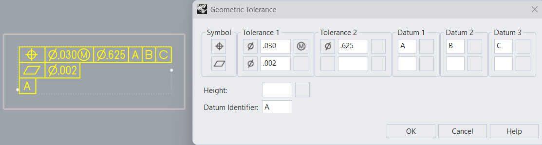
- Fill out the form as suggested:
- Press OK.
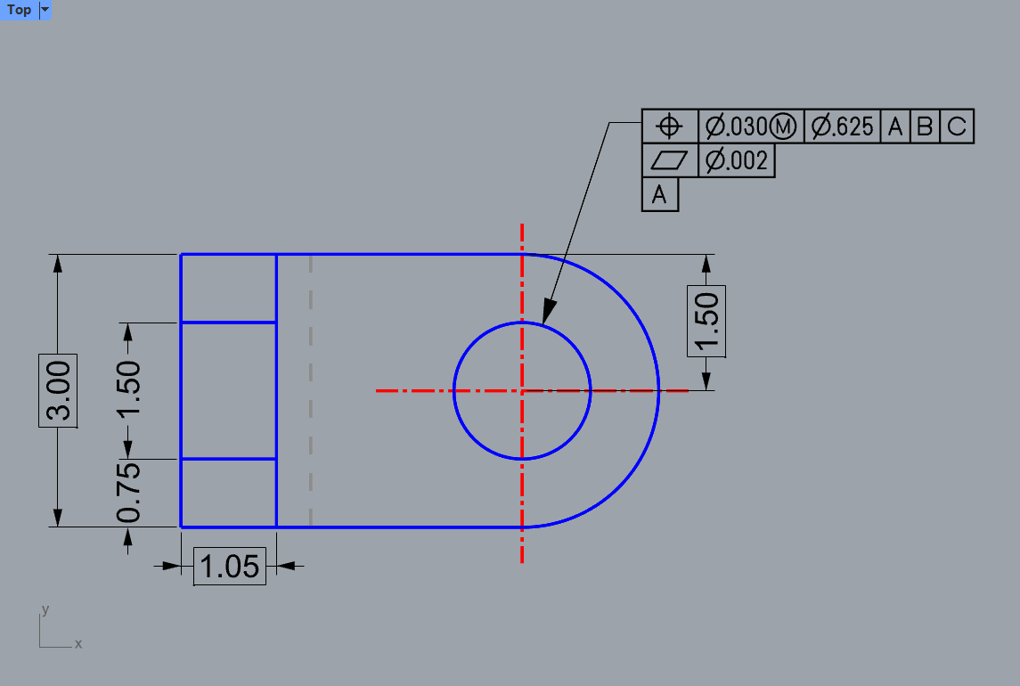
- At the
Geometric tolerance locationprompt , snap to theEndof the Leader arrow: - Try it on your own! Experiment with your own models.
- Share comments and feedback on the Rhino Forum.
Shapes in Linetypes
- Download Rhino 9 Evaluation for Windows or Mac.
- Download and open the Shapes_Text-in-Linetypes.3dm model in Rhino.
- Run the
 Linetypes
command to open the Linetypes panel.
- In the Linetypes panel, click the
 New
button to create a new linetype.
- Name the new linetype
Storm Drain. Press Enter. - In the panel, scroll down to the Shapes section:
- In the
 Layer
panel:
- Find the
Storm Drainlayer. - Open the Linetype property for this layer.
- In the Select Linetype dialog, select
Storm Drain. - Press OK.
- Find the
- The green curve is in the
Storm Drainlayer. It will automatically update to the newStorm Drainlinetype. - Try it on your own!
 Unlock
the rest of the geometry and repeat the same process for Gas Line, Fence1, and Fence2. Assign each newly created linetype to its corresponding layer.
- Share comments and feedback on the Rhino Forum.
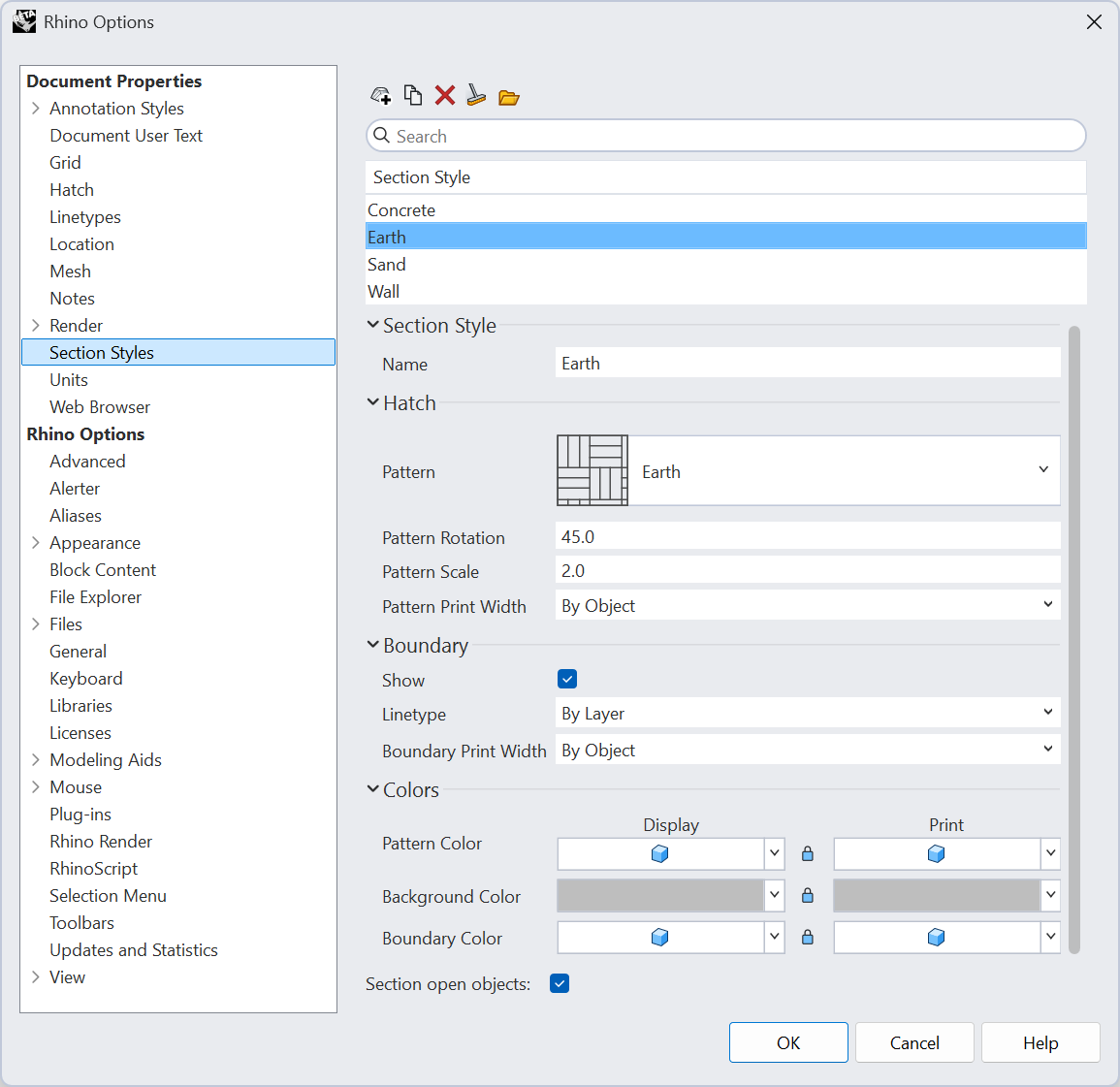
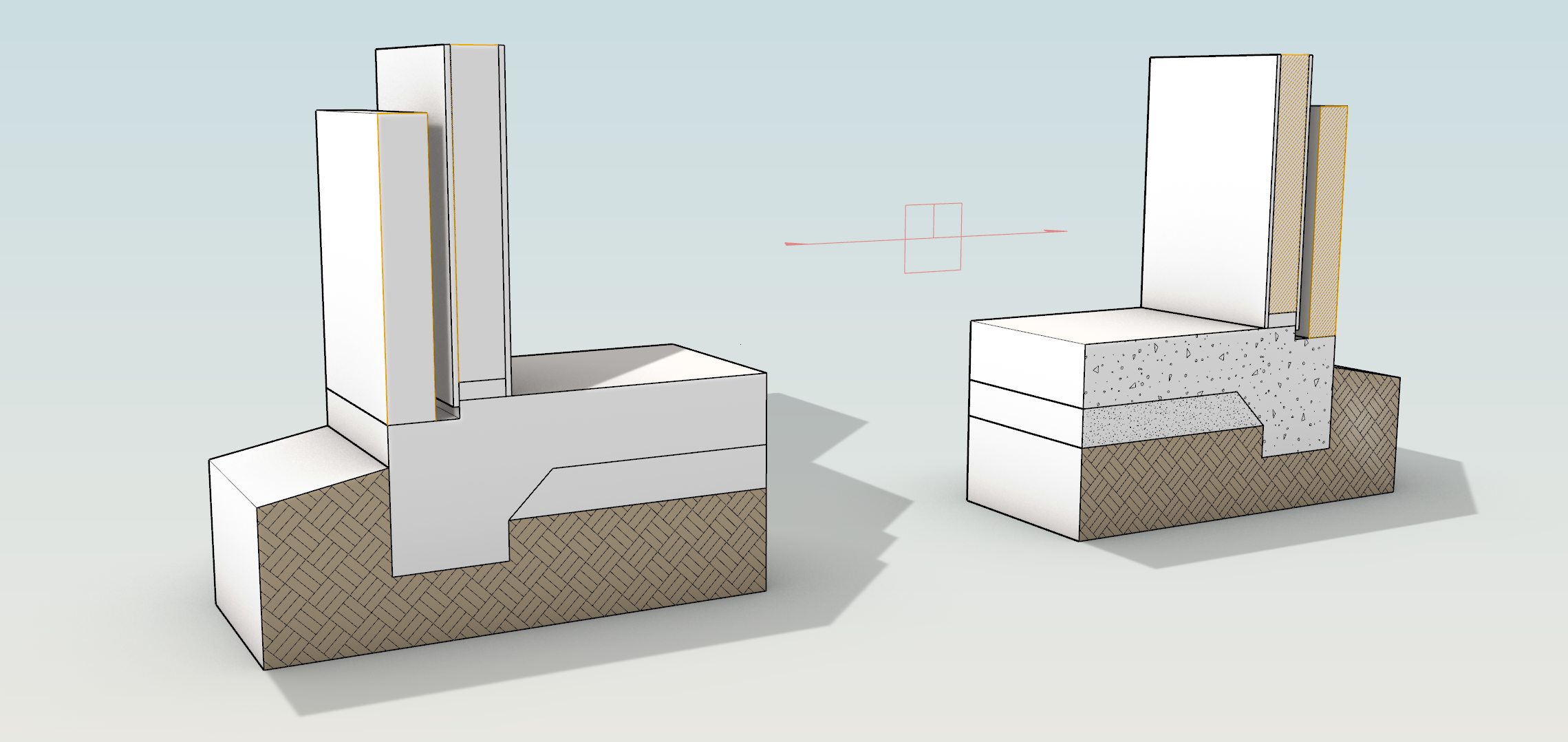
Section Styles
- Download Rhino 9 Evaluation for Windows or Mac.
- Download and Open DocumentSectionStyles-TryIt.3dm in Rhino .
- To create a style:
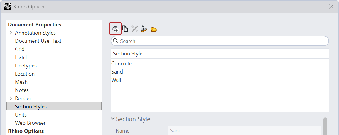
- Go to the File menu > Properties > Section Styles.
- Select the New icon to create a new Document Section Style.
- In the dialog:
- Rename the style from
Section Style 01toEarth. - Set the Hatch Pattern to
Earth. - Set the Pattern Rotation to
45degrees. - Set the Pattern Scale to
2. - Set the Background Color to
Gray. - Press OK.
- Rename the style from
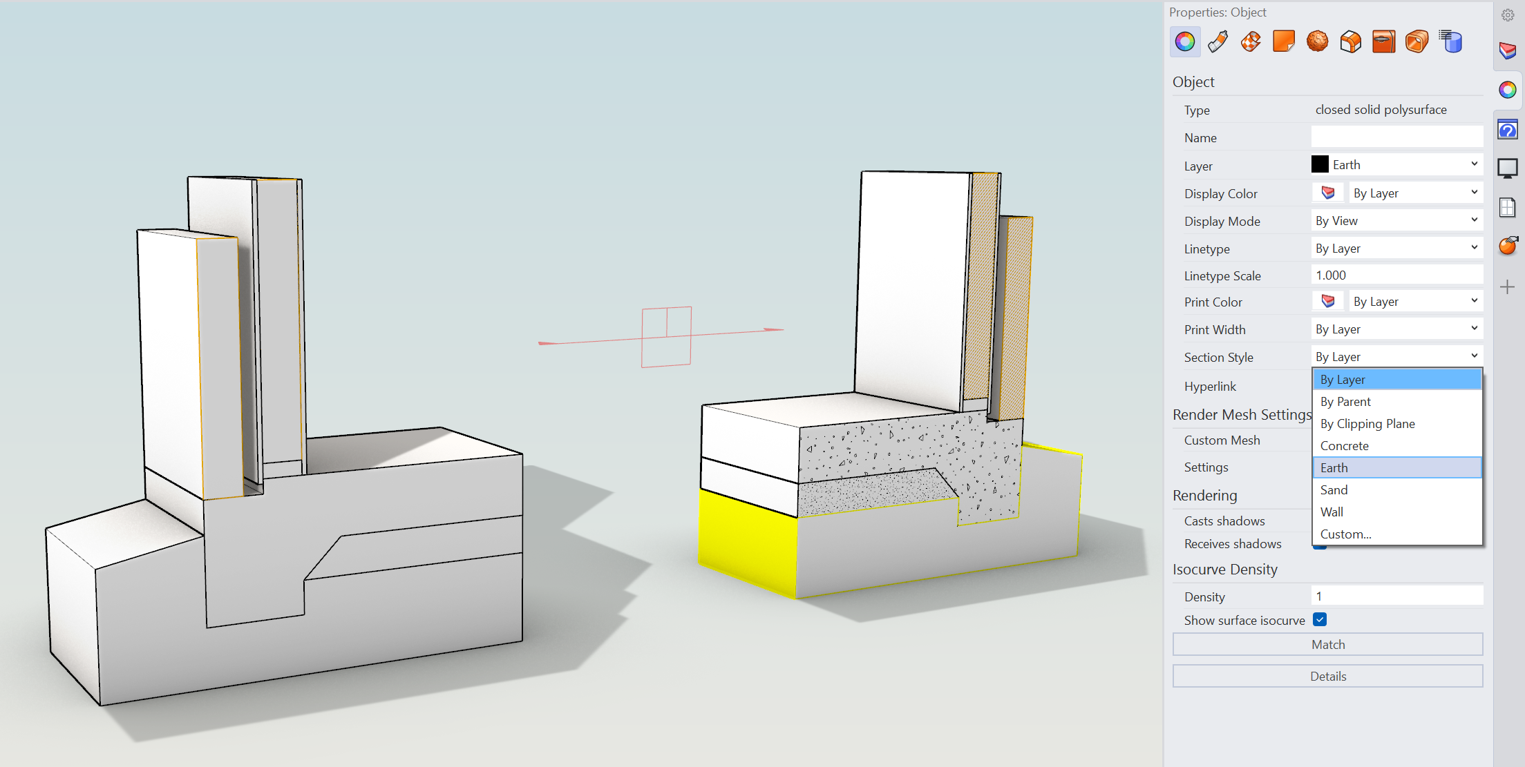
- Apply the style to an object:
- Select the bottom base object in the model-
- Open the Properties
panel.
- In the Section Style drop-down, choose
Earth.
- Apply the style to a second object:
- Select the matching object on the opposite side of the model.
- In Properties
, select
Earthfrom the Section Style drop-down list.
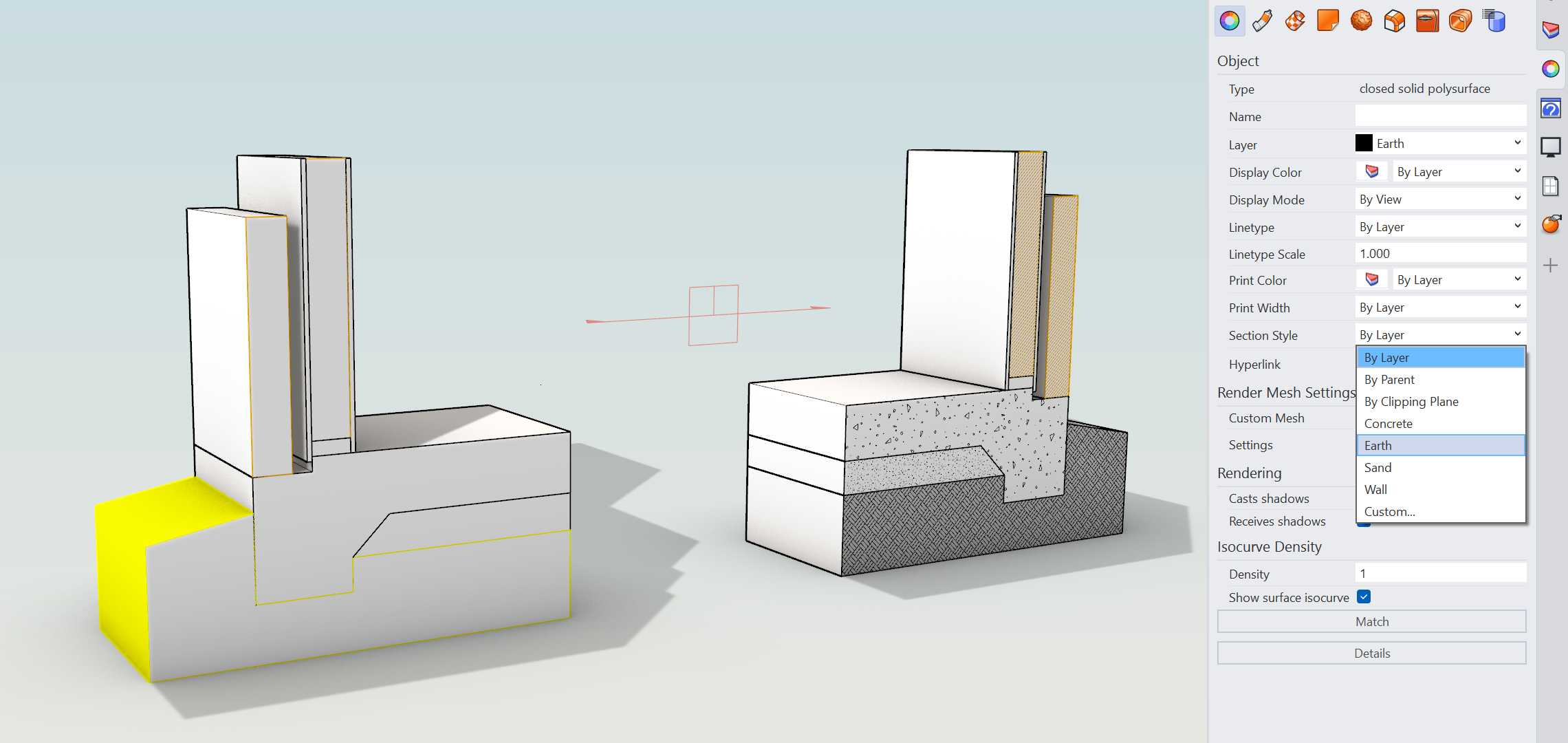
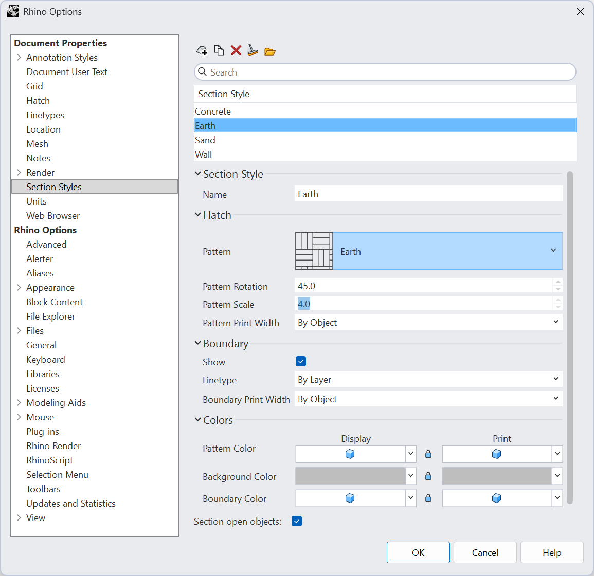
- Edit once, update everywhere:
- Go back to Document Properties > Section Styles page
- Select
Earth - Change one of its settings, such as Pattern Scale or Background Color.
- Both objects using the
Earthstyle update at the same time.
- Apply the remaining Document Section Styles. The objects on the right side of the model already use the
Sand,Concrete, andWallstyles. - Try it on your own! Try applying Section styles per layer on your favorite models.
- Share comments and feedback on the Rhino Forum.
Clipping Drawings
- Download Rhino 9 Evaluation for Windows or Mac.
- Download and open the ClippingDrawing.3dm model.
- From the Layers panel:
- Make sure the
Site3Dlayer is OFF . - Make sure the
ClippingSectionslayer is ON.
- Make sure the
- Maximize the viewport.
- Turn on the
PointOsnap . - Run the
 ClippingDrawings
command.
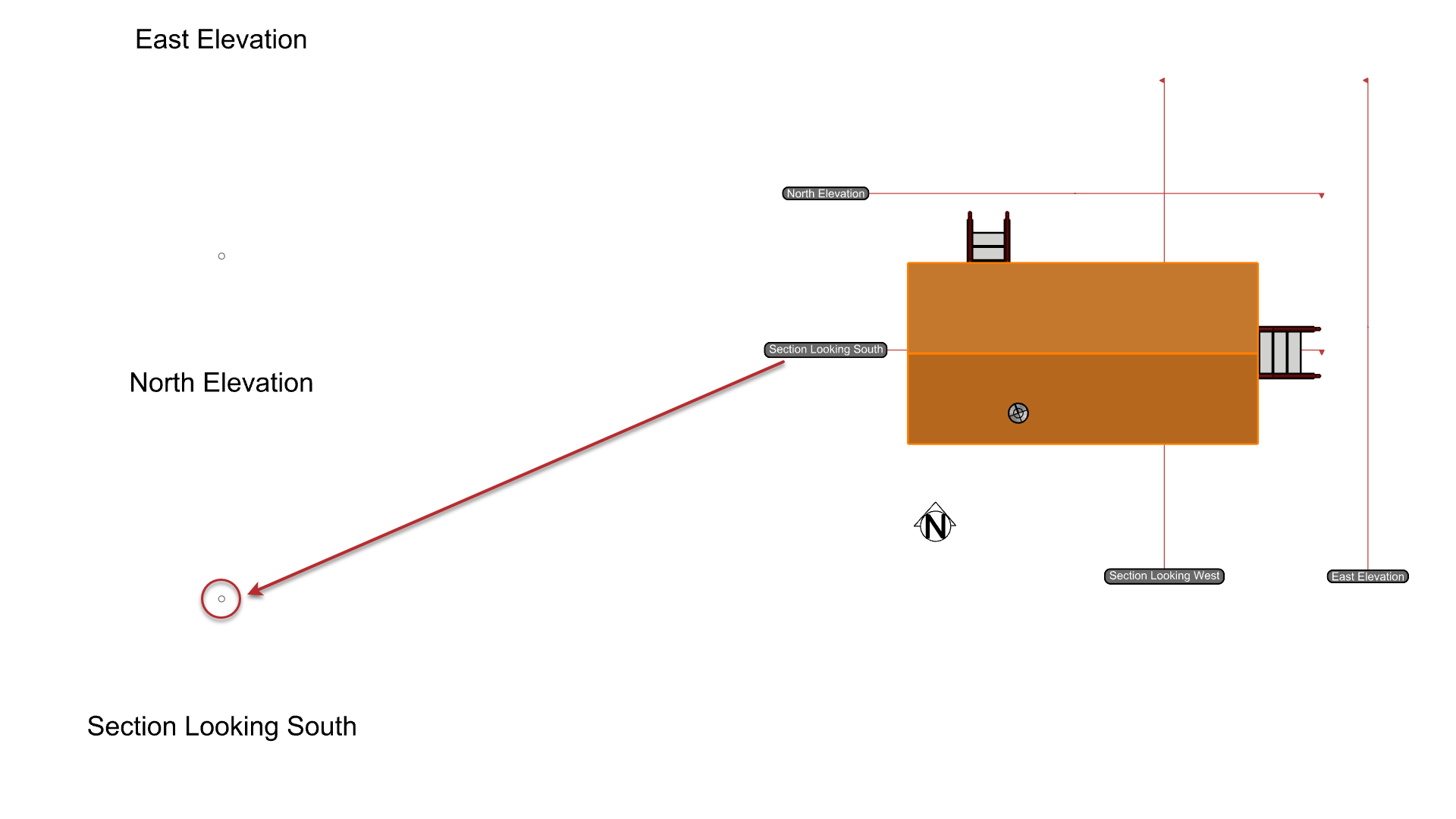
- At the
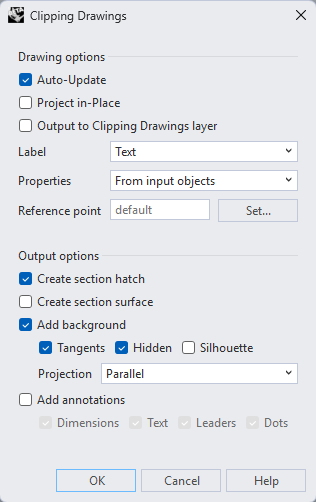
Select clipping sectionsprompt , select the Section Looking South clipping plane. Press Enter. - In the Clipping Drawings dialog, select :
- In Properties:
From Input Object Add BackgroundwithTangentsandHiddenoptions.- Click
OKand place the clipping drawing in its corresponding location to the left.
- In Properties:
- At the
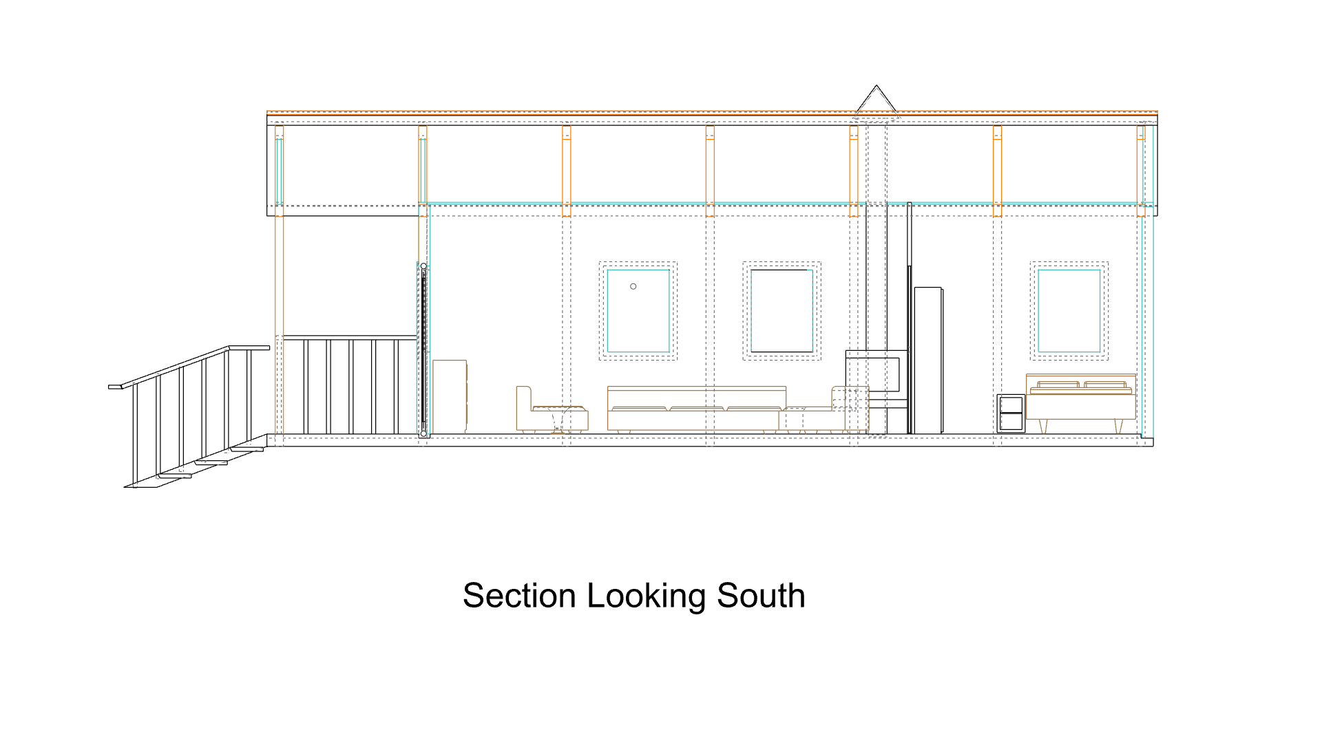
Placement pointprompt, snap to the point above Section Looking South. - The section has been created:
- Try it on your own! Create the Section Looking West and the Elevations.
- Share comments and feedback on the Rhino Forum.
Polyline: Offset
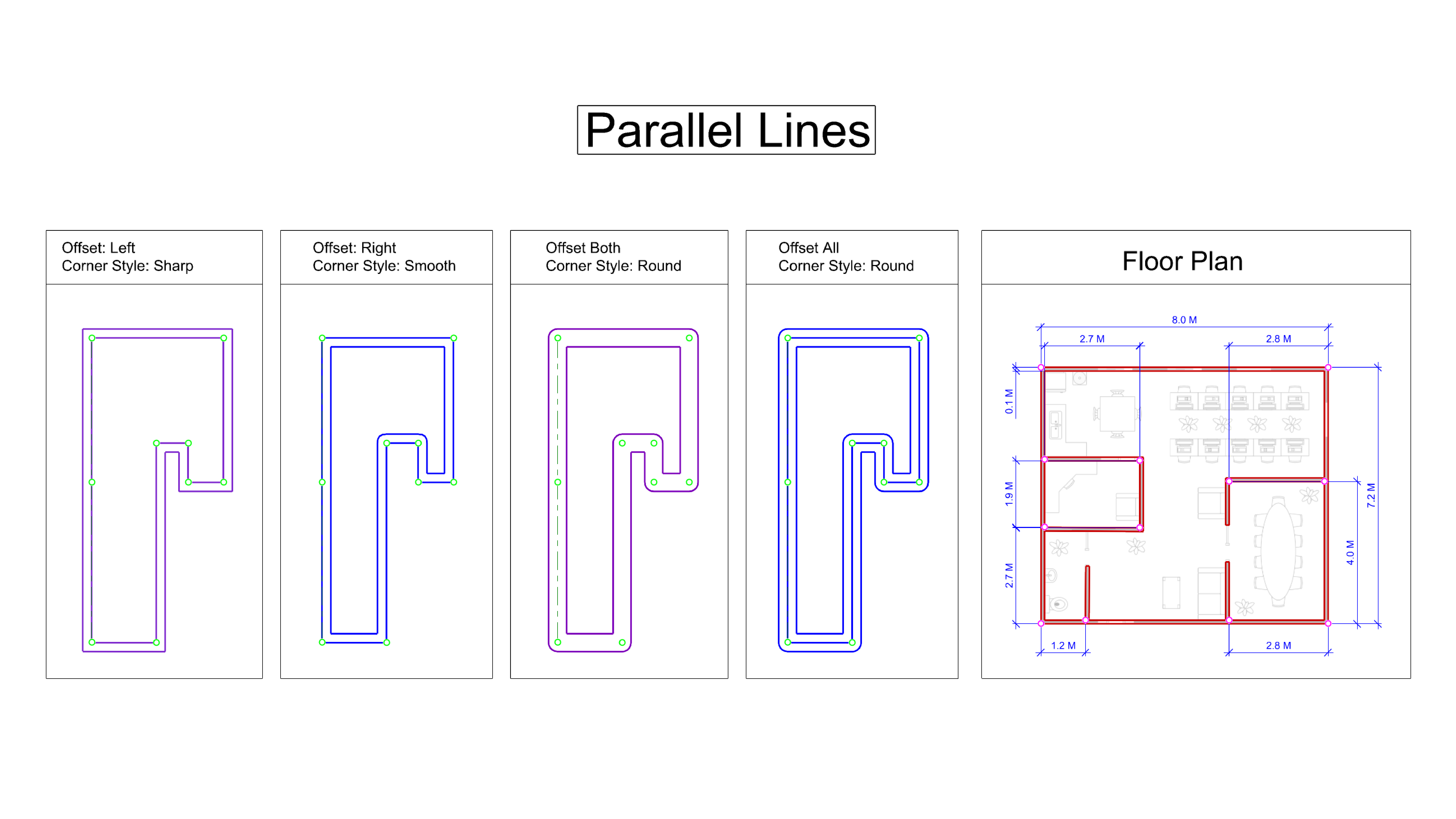
- Download Rhino 9 Evaluation for Windows or Mac.
- Download and open the Try-It-Parallel-Lines.3dm model.
- Zoom in to the
Offset: Leftframe. - Turn the
PointOsnap on. - Run the
 Polyline
command.
- Set the following options in the
Command Prompt
:
- Set
Offsetto Left. - Set
OffsetDistanceto 0.25. - Set
CornerStyleto Sharp. - Set
CapStyleto Flat. - Pick the points as shown.
- Set
- Zoom in to the
Offset: Rightframe and make theOffset Rightlayer current . - Run the Polyline
command and set the following options:
- Set
Offsetto Right. - Set
Offset Distanceto 0.25. - Set
Corner Styleto Smooth. - Pick the points as shown.
- Set
- Zoom in to the
Offset: Bothframe and make theOffset Bothlayer current. - Run the Polyline
command and set the following options:
- Set
Offsetto Both. - Set
Offset Distanceto 0.25. - Set
Corner Styleto Round. - Pick the points as shown.
- Set
- Zoom in to the
Offset: Allframe and make theOffset Alllayer current. - Run the Polyline
command and set the following options.
- Set
Offsetto All. - Set
Corner Styleto Round. - Pick the points as shown.
- Set
- Zoom in to the
Floor Planframe and make theWallslayer active. - Run the Polyline
command and set the following options:
- Set
Offsetto Right. - Set
Offset Distanceto 0.1. - Set
Corner Styleto Sharp. - Set
Capto Flat. - Pick the points as shown.
- Set
- Turn off the
Image and Pointslayers. - Use
 Trim
to complete any additional cleanup.
- Try it on your own! Experiment with the different
Offset,Corner Style,Offset Distance, andCap optionsto create your own parallel-line conditions. - Share comments and feedback on the Rhino Forum.
Layouts
HatchPattern: Create
The  HatchPattern
command allows you to create your own hatch patterns. These get saved in the 3dm file and can be reused in other projects. This is handy to build a custom library to represent materials or patterns specific to a project.
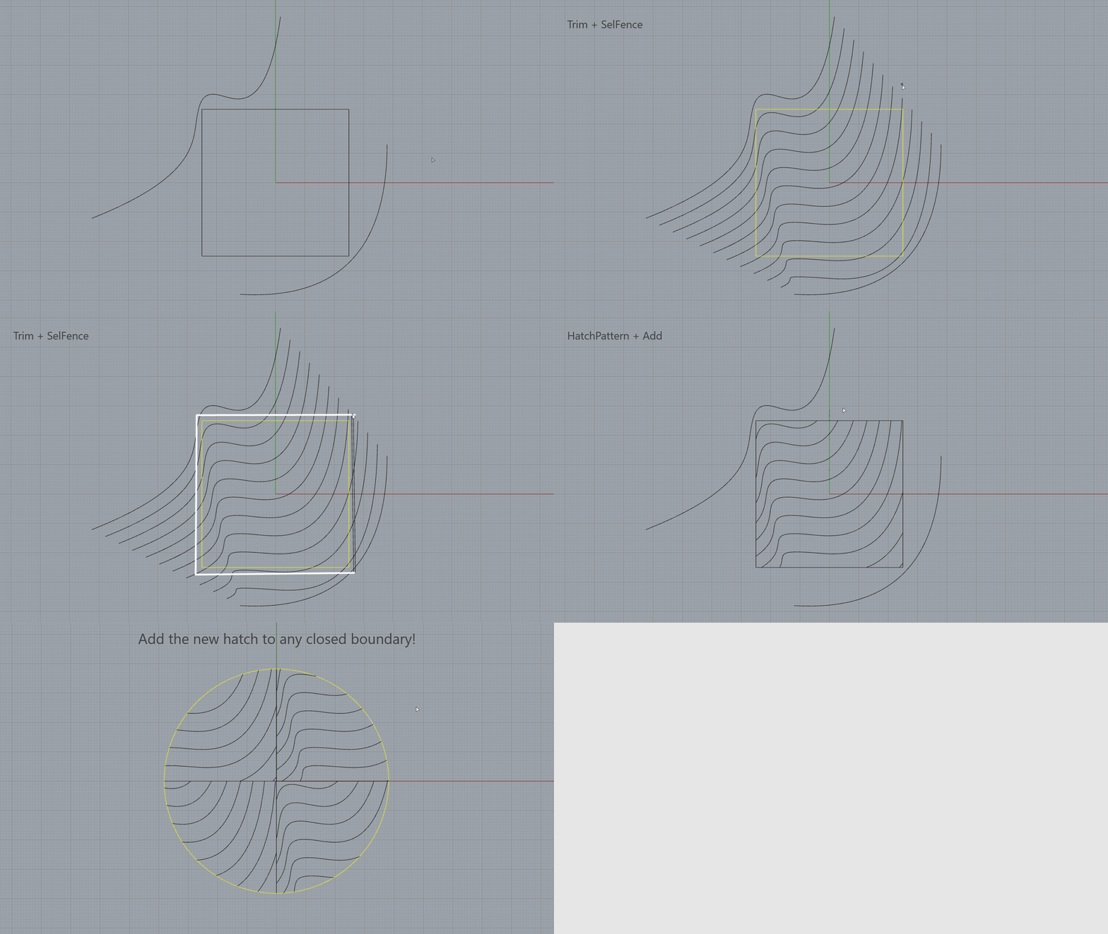
- Download hatch-create.3dm.
- Run the
 TweenCurves
and press
.
- At the Select start and end curves prompt , select the two wavy curves.
- At the Press Enter to accept options prompt , type 10 and twice.
- Run the Trim
command.
- At the Select cutting objects prompt , select the square and press .
- At the Select object to trim…
prompt
, select the
Fenceoption. - Click and drag a fence around the square to trim the exceeding curves.
- Run the HatchPattern
command.
- At the Choose hatch pattern option
prompt
, select the
Addoption. - At the Pattern tile rectangle prompt , snap to the End osnap of the square.
- At the Other corner or length prompt , snap to the opposite End of the square.
- At the Select curves to define pattern prompt , , window select the trimmed curves.
- At the Hatch pattern name prompt , type waves.
- Press to end the command.
- Run the
 Hatch
command to add your pattern to any closed boundary!
Analysis
Zebra: Surface Analysis
- Download Rhino 9 Evaluation for Windows or Mac.
- Download and open NewZebra.3dm in Rhino.
- Run the Zebra
command in the
prompt
. Press Enter.
- At the
Select objects for zebra stripe analysisprompt , window select all objects in the scene. Press Enter. - In the
Zebradialog:- Select
Rainbowunder theModedropdown menu. - Adjust the
Frequency,Rotation,SizeandBlursliders. - Hold down the right-mouse button to rotate the view. Notice that the
Rainbowpattern on the model moves as you change viewing angles. - Check
Staticand rotate the view again. This time, you will see that theRainbowpattern is stationary.
- Select
- Check the
Show wiresoption to display the surfaces’Isocurveswhile theRainbowanalysis mode is active. - Try this on your own surfaces.
- Please ask questions and give feedback on the Discourse Forum.
Global Edge Continuity
- Download Rhino 9 Evaluation for Windows or Mac.
- Download and open GEC-tryit.
- Run the GlobalEdgeContinuity
command.
- Window select all surfaces and press .
- Rhino immediately calculates the edge continuity between the selected surfaces and displays the results in the Global Edge Continuity dialog.
- Edges that are G0 continuous will be marked gray.
- Select the button in the dialog.
- Notice that some edges turn blue, indicating that these are tangency continuous.
- Select the button in the dialog.
- Notice that some edges turn white, indicating that these are curvature continuous.
- Turn on
Show Filtered G1 and G2 edges. When this option is on, edge pairs that exceed the Evaluation Settings Filter G1 and G2 values will not be displayed. - Select the label in the viewport with number 6.
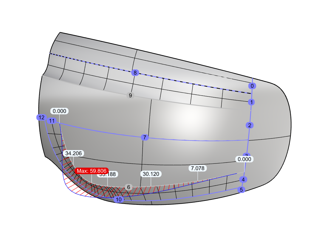
- Notice that this edge gets focus and displays a graph and deviation information in the viewport.
- Try this on your own surfaces.
- Please ask questions and give feedback on the Discourse Forum.
Display & Rendering
Hide in Viewports
The  HideInViewports
command hides selected objects in specific viewports only, while they stay visible in others. This can be helpful when sketching, presenting different design iterations in viewports side-by-side or hiding annotations in a certain Detail.
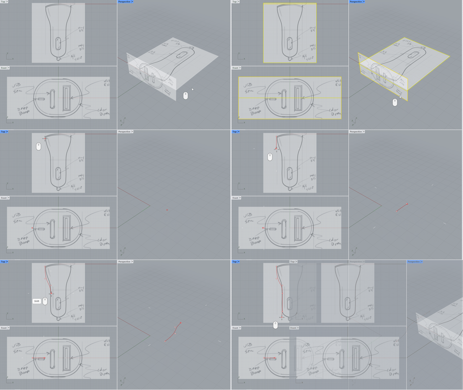
- Download and open the sketch.3dm in Rhino.
- Run the HideInViewports
command and press
.
- At the
Select objects to hide in some viewportsprompt , select the two images in the . Press . - At the
Click in each viewport the objects should be hidden inprompt , select the viewport. Press or right-click to end the command. - The images have disappeared from the viewport.
- Run the
 Curve
command.
- Start tracing away! You can visualize and edit the resulting curve in the Perspective viewport without the images getting in the way.
- To bring them back, run the
 ShowInViewports
command.
Rendered Mode: Transparency
- Download Rhino 9 Evaluation for Windows or Mac.
- Download and open the Pipes.3dm model.
- Maximize the Perspective viewport.
- Change Display Mode to Rendered. The glass objects will appear transparent and visualize color and simulate refraction.
- Ask questions and give feedback on Rhino’s Discourse Forum.
Decals
- Download Rhino 9 Evaluation for Windows or Mac.
- Download and open the VelmoreBox.3dm model. You’ll find a box with a Decal applied to it.
-
Select
the top box:
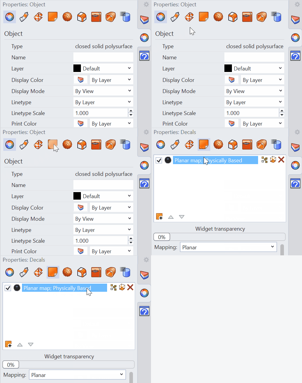
- In the Properties
Panel, select the Decal icon.
- Select the Decal texture in the list.
- In the
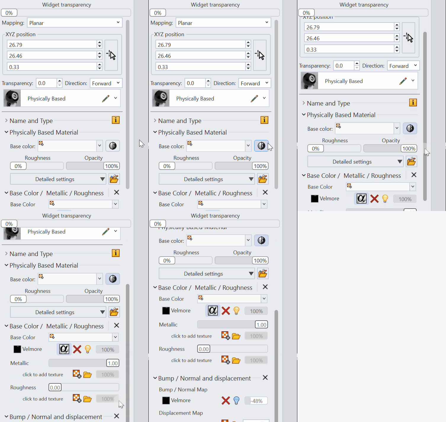
- We’ll define the material properties for the Decal. Scroll down in the panel:
- Select the Metallic button to give a metallic finish.
- Select the Bump Map light bulb icon to turn the bump map On.
- Change the Display Mode to Raytraced to get a physically correct image.
- Try it on your own! Experiment with other settings in the panel.
- Share comments and feedback on the Rhino Forum.
Caustics and Dispersion
- Download Rhino 9 Evaluation for Windows or Mac.
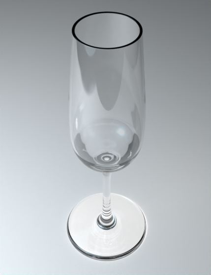
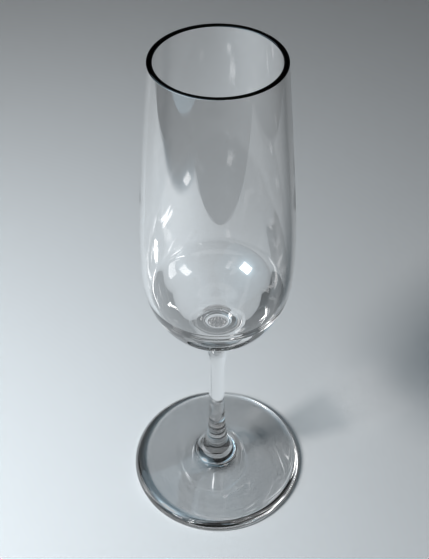
- Download and open the tryit-caustics.3dm model. You’ll find a scene with a champagne glass, ready to render.
- Click in the Perspective view to make it the active viewport.
- The file is set to render at the viewport resolution, using the
Architecturepreset, which is the standard - No caustics or dispersion are enabled. - If you would like to see the scene rendered with these standard settings, simply run the
 Render
command.
- In the
 Rendering
Panel, enable the
Productoption underRhino Render Advanced Settings > Presets. - Then Render
the same scene to see how the light and transparent glass material interact differently than before, resulting in more realism.
- Try it on your own! Experiment with your own lighting and material setups.
- Share comments and feedback on the Rhino Forum.
Markups
- Download Rhino 9 Evaluation for Windows or Mac.
- Download and open the subd-car-seat.3dm model.
- Run the
 Markup
command, and the Markup HUD will appear.
- Choose the Sketch icon at the top of the HUD.
- Change the line thickness using the Thickness slider at the bottom of HUD.
- Begin drawing in the viewport. Press Enter when done.
- Select the Text icon.
- Select a point to place the text in the view.
- Type your text. Press Enter when done.
- Select the green checkmark at the bottom-right corner of the view.
- The Markup
is created and the Markups Panel opens.
- Edit, delete or restore a Markup from the panel.
- Try it on your own! Experiment with the other tools within the Markup HUD.
- Give us feedback! Ask questions on the Discourse Forum.
User Interface
RhinoAI
- Download Rhino 9 Evaluation for Windows or Mac.
- Inside Rhino: Run the
 AI
command to dock the chat beside your model. Use the options on the
 AI Settings
to choose your AI provider and set which tools the assistant can use.
- Check that it works. Start a new chat and enter the following prompt:
Test Prompt“Make me a box.”
- A box should appear, and the assistant will describe what it did.
- Your Rhino AI
is ready to use!
- Find more RhinoAI Examples here
- Please ask questions and give feedback on the Discourse Forum.
Transfer Settings
- Download Rhino 9 Evaluation for Windows or Mac.
- Open Rhino.
- Run the
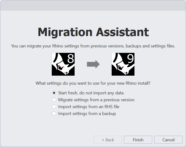
 OptionsMigrate
command. A dialog will appear.
- Select the option that works best for your situation.
Start fresh, do not transfer any data> Do not import any settings from the previous version.Import data from a previous install> Migrate all of your settings from V7 or V8 (Windows) or V8 (MAC).Load Rhino from exported settings> Import from your own settings file (*.rhs).Import data from a backup> Load settings from a backup.
- Restart Rhino for these changes to take effect.
- If you chose an option that imports settings from a previous version or file, all your previous settings should be applied to your new Rhino 9 installation upon restart.
- Now run the command
 OptionsExport
. This creates a backup file of all your newly created Rhino 9 preferences and allows users to keep it as a backup for future restoration or share a preference file with a class or studio.
- Please ask questions and give feedback on the Discourse Forum.
Instant Aliases
- Download Rhino 9 Evaluation for Windows or Mac.
- Download and open the ia-floorplan.3dm model.
- The Top view will be zoomed to focus on a portion of the floorplan.
- Run the Options
command, or go to the Tools menu > Options > Aliases.
- Search for the ZE alias that corresponds to the
'_Zoom _Extentscommand macro. - In the the far right column titled Instant +/-, select to add a check mark to
'_Zoom _Extents. This will enable the instant functionality. - Press the button in Options to save the changes.
- Type ZE in the
Command Prompt
without pressing Enter. The
'_Zoom _Extentsmacro will zoom the Top view to the extents of the entire floorplan. - Try it on your own! Enable this on your favorite commands and macros!
- Please ask questions and give feedback on the Discourse Forum.
Toolbars, Refined
- Download Rhino 9 Evaluation for Windows or Mac.
- Run the
 Toolbar
command.
- The New Toolbar Explorer window will show, all toolbar editing is now done here.
- Create a new RUI -
File>New RUI File. You will then select a location to save the new RUI file. - Click the All RUI Files button at the top of the Toolbar Explorer window to show your new RUI in the list.
- Click the Toolbars button on the new RUI.
- Double click your new Toolbar in the list.
- Customize your new Toolbar by editing the name, the buttons and the icons.
- Float your new Toolbar - In the list of new toolbars, show the toolbar by turning on the lightbulb!
- Please ask questions and give feedback on the Discourse Forum.
Large Projects
Audit 3dm Files
- Download Rhino 9 Evaluation for Windows or Mac.
- Download and open the Audit3dmFile-Demo.3dm model.
- Run
 Audit3dmFile
and press Enter.
- Select the
AuditThisFileoption in the prompt. - Click on the largest rectangles in the Tree Map: those are the biggest objects in the file.
- Right-click one of the rectangles and select
Zoom to object in Rhino. - Result: the object is maximized in the Rhino viewport. You can inspect it or delete to troubleshoot the file.
- Try it on your own! Audit your “favorite” 3dm file.
- Share comments and feedback on the Rhino Forum.
Blocks
Download the model of a partial 3D plan of a kitchen. You will need to add the microwave, range top and double ovens.

- Download Rhino 9 Evaluation for Windows or Mac.
- Download and open the Blocks-Demo.3dm model.
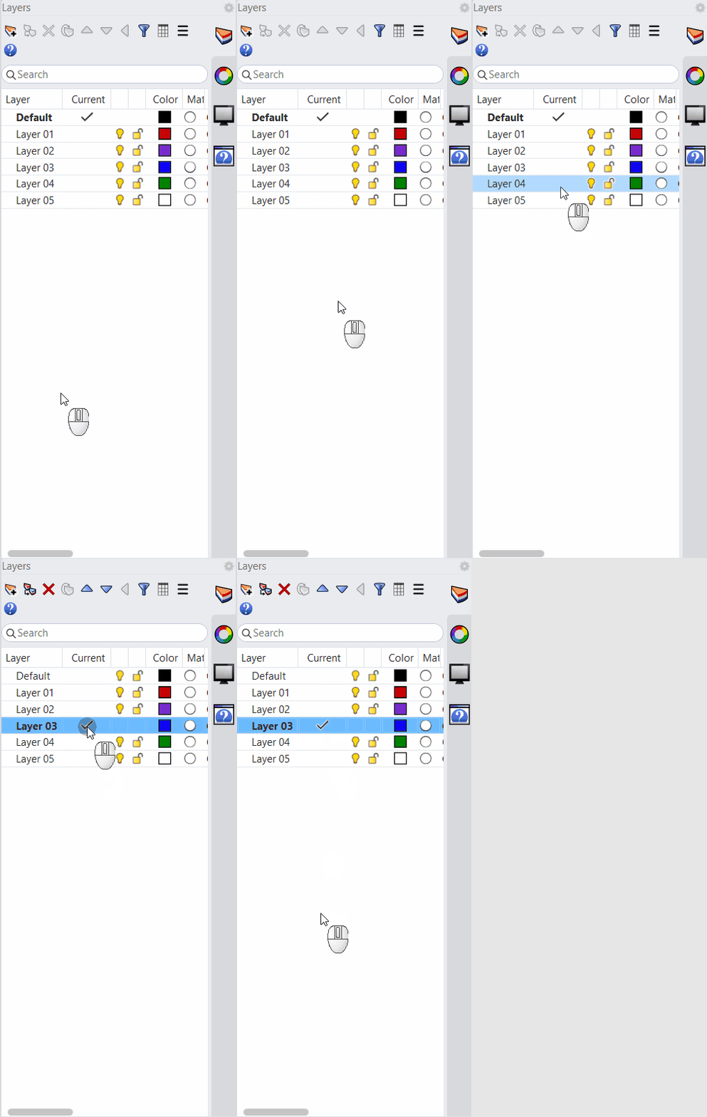
- Type the Layer command to open the Layers panel in the right sidebar.
- In the Layers panel, verify that the Ovens & Range layer is current. The check mark should appear in the Current column of the Layers panel.
- Type the BlockManager command. This will open the Block Definitions panel in the right sidebar.
- Type the Osnap command.
- On the command line, pick Point=On, and pick the Off setting for all other osnaps. This can also be done in the Osnap panel.
- In the Blocks Definitions panel on the right sidebar, right-click on Double Oven block.
- On the right-click menu, pick the “Insert” option.

- At the “Insertion point” prompt, pick the block insertion point where indicated by the leader.
- At the Scale factor <1>, prompt, type 1 or Enter to accept the 1 in brackets.
- At the Rotation angle <0>, prompt, type 0 or Enter to accept the 0 in brackets.
- Repeat this process for the Microwave and Range Top blocks.
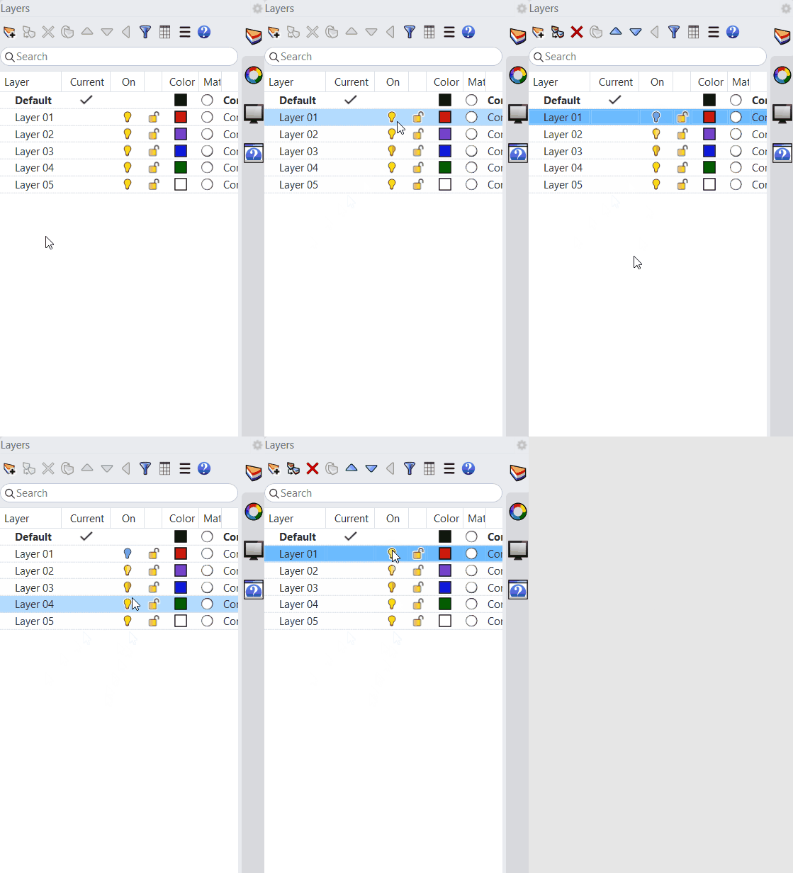
Locate these blocks at their respective insertion locations as indicated by the leaders. - Turn on the countertop geometry by going to the Layers panel and picking the gray light bulb icon in the On column of the layer Turn On When Done.
- Turn off points and leaders used to locate the block by going to the Layers panel and picking the yellow light bulb icon in the On column of the layer Turn Off When Done.
Now your 3D kitchen model is complete.
Ask questions and give feedback on the Discourse Forum.
Grasshopper
Grasshopper: Hatch
Use the Model Hatch Component to generate parametric Voronoi hatches inside a boundary curve. Adjust rotation, scale, base point, background color, and fill style to control the appearance.
- Download Rhino 9 Evaluation for Windows or Mac.
- Download and open the Voronoi2D.gh model.
- Download and open the definition in
 Grasshopper
. The file contains a parametric 2D Voronoi pattern that will become a hatch pattern.
- In Rhino:
- In Grasshopper:
- Right-click the Curve Parameter (highlighted in red) connected to the Model Hatch Component, select
Set one curve. - Play around with the
RotationandScale Number Slider
in the Model Hatch Component. See how the pattern updates in the viewport.
- Right-click the Curve Parameter (highlighted in red) connected to the Model Hatch Component, select
- Share comments and feedback on the Grasshopper Forum.
 Circle
Grasshopper Components
Grasshopper: Clip & Section
- Download Rhino 9 Evaluation for Windows or Mac.
- Download and open the Multistory_House.3dm in Rhino.
- Download and open the TryIt_Clipping_Plane_GH_v9.gh file in Grasshopper
- Change the value of the Number Slider
controlling the
Z-coordinateof the Clipping Plane. - Click on the
Updatebutton on the Create Clipping Drawing component to generate a 2D drawing. - After the drawing has been created, click the
Pushbutton on the Content Cache component to add the drawing to the Rhino document. - After any change to your model, simply repeat steps 5 and 6 to update and push the drawing to the document which will replace the existing drawing with the updated version.
- Try this with your own models by replacing the
Model Objectspassed into theObjectsinput of the Create Clipping Drawing component. - Ask questions and give feedback on the Discourse Forum.
Grasshopper: Render Materials
- Download Rhino 9 Evaluation for Windows or Mac.
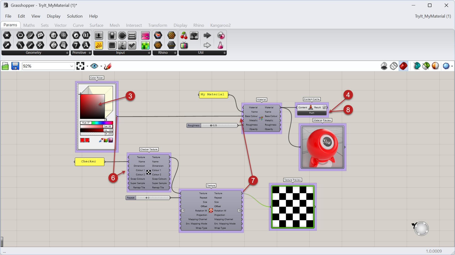
- Download and open the TryIt_MyMaterial.gh file in Grasshopper
in Rhino 9.
- In the Grasshopper canvas, change the color in the
 Color Picker
and note the Material Preview updates.
- Press the
Pushbutton in the Content Cache
component.
- In Rhino, open the
 Materials
panel to see the resulting pushed material.
- Connect the output of the Color Picker
in Grasshopper to the
Colour 1input on the Texture. - Replace the
Base Colorof the Material component with the repeated Checker Texture. Pushthe content again and note the material updates in the Rhino document.- With each additional push of the content, the objects will be replaced and will always have unique texture mapping for each.
- Try this on your own by changing other parameters in the components.
- Share comments and feedback on the Grasshopper Forum.
Grasshopper: Textures
- Download Rhino 9 Evaluation for Windows or Mac.
- Download and open the Try_GH_Textures.gh file. This document contains several of the new texture components found in Rhino 9. Using this file, you can make and edit multiple procedural fBm textures easily.
- To open this file, start Rhino 9 followed by Grasshopper using the Grasshopper
command. In the Grasshopper File menu, open the file downloaded in step 1.
- In Rhino, open the Textures panel using the
 Textures
command. This panel will show 2D textures used in and saved to the open 3dm file.
- Return to the Grasshopper canvas and click the Bake Content button on the Content Cache component. This will create a texture in the Rhino document named “My fBm texture 1” which can be seen in the Textures panel.
- Use the control knob component at the beginning of the Grasshopper file to change the numeric value to 2.
- Drag the handle on the number slider connected to the Roughness value of the fBm Texture component to 0.5.
- Drag the handle on the number slider connected to the Octaves value of the fBm Texture component to 7.
- Edit the number connected to the Gain value of the fBm Texture component to 4 by double-clicking the numeric value on the slider.
- Click the Bake Content button on the Content Cache component. This will create another texture in the Rhino document named My fBm texture 2 which can be seen in the Textures panel.
- Experiment with other settings combinations including color swatch changes. If the control knob uses a value previously baked, the new texture will overwrite the previously baked one of the same name. Use new control knob values before baking for unique texture names.
- Please ask questions and give feedback on the Discourse Forum.
Grasshopper: Texture Mapping
- Download Rhino 9 Evaluation for Windows or Mac.
- Download and open the Doric_Column.3dm model in Rhino.
- Download and open the TryIt_Mapping_GH_v9.gh file in Grasshopper
.
- Select the two polysurfaces representing the columns in the Rhino viewport.
- In the Grasshopper canvas, right-click the
 Model Object
parameter and select
Set many model objects. - Press the
Pushbutton in the Grasshopper Content Cache
component. Note that the columns created each have unique texture mapping using the procedural marble material defined in the *.ghfile. - Change the value of the Number Slider
controlling the
Sizein the Texture Cluster . Pushthe content again to see the change in the texture mapping, as in step 6.- In the
 Horizontal Frames
component, change the value in the
Number of columnsslider to increase or decrease. - With each additional
Pushof the content, the objects will get replaced and will always have unique texture mapping per object. - Try this with your own models by replacing the model objects referenced in step 5.
- Share comments and feedback on the Grasshopper Forum.
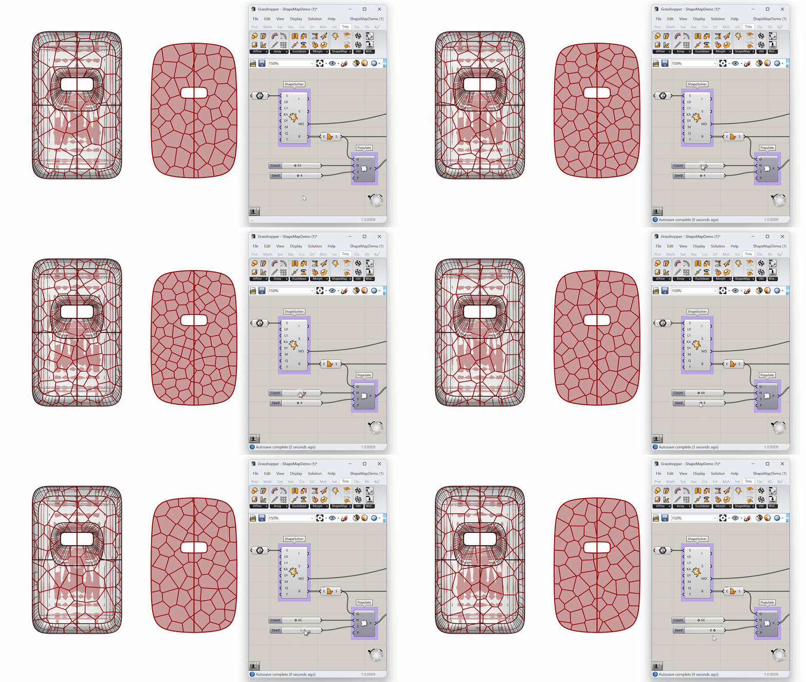
Grasshopper: ShapeMap
- Download Rhino 9 WIP for Windows or Mac.
- Download and open the ShapeMapDemo_Step3.3dm file.
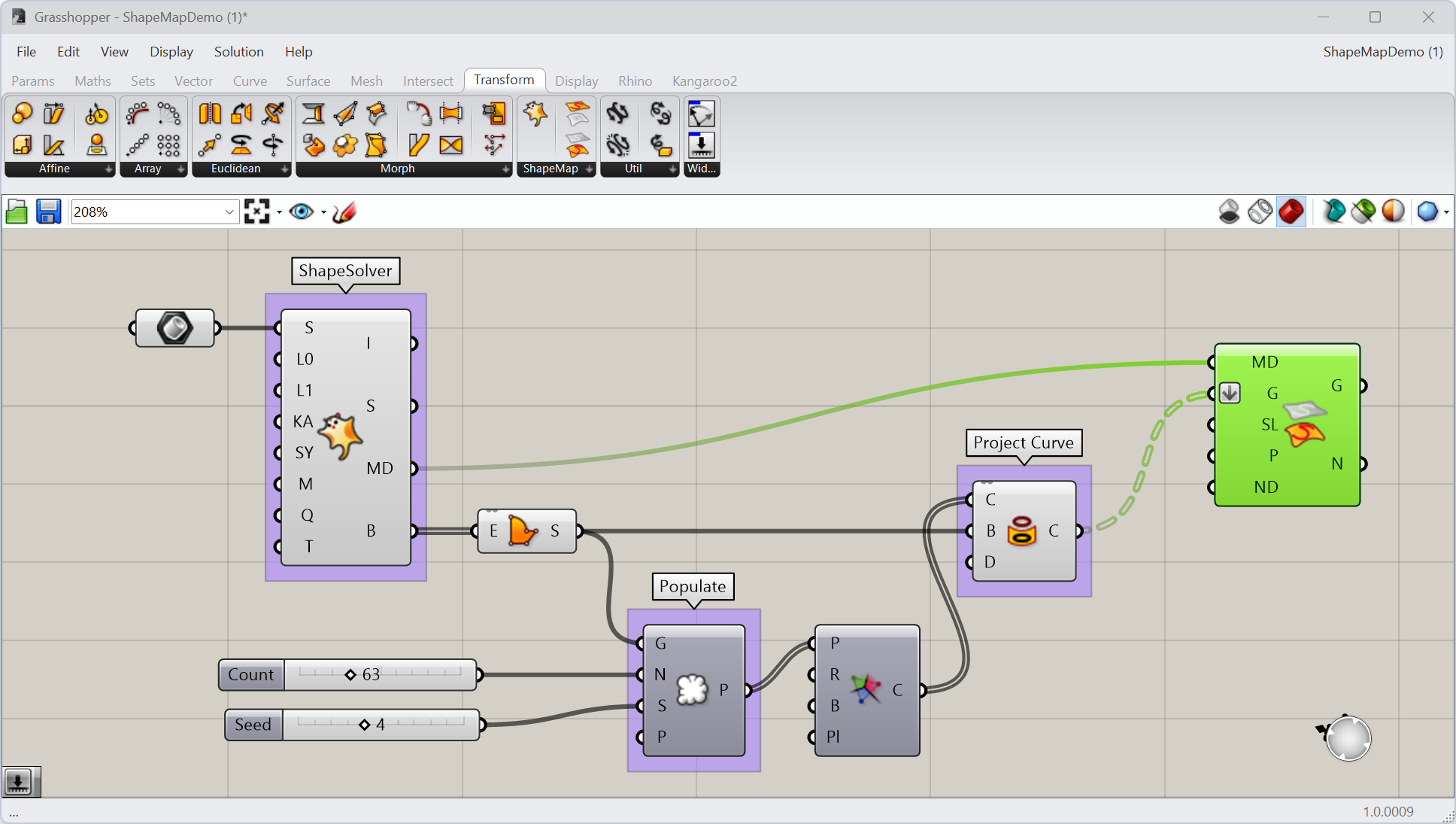
- Download and open the ShapeMapDemo.gh file in Grasshopper
definition. This definition already includes the ShapeSolver and
 Project Curve
components used to unroll the 3D shape and prepare a 2D curve pattern.
- In Grasshopper:
- Add a MapToShape component to the canvas, found under Transform > ShapeMap.
- Connect the
MapDataoutput of the ShapeSolver component to the corresponding input on MapToShape. - Connect the
C(Curve) output of Project Curve
to the G(Geometry) input on MapToShape. - Right-click on this G input and select
Flatten. This will resolve the Data Matching error. - Adjust the Number Slider
connecting to the
CandSinputs of the Populate Geometry
component.
- Try it on your own shape! Or download and play with the ShapeMap_Archi1.gh example file.
- Please ask questions and give feedback on our Discourse Forum.
Grasshopper: Content Viewer
- Download Rhino 9 Evaluation for Windows or Mac..
- Download the ContentViewer.gh example file.
- Drag and drop the file inside Rhino. It will load Grasshopper
.
- The file contains two examples:
- Visualize Hatch Patterns:
- Right-click the
 Query Model Hatch Pattern
component.
- Select
Add Default Patternsto load Rhino’s default hatch pattern library. - Select different Hatch Definitions in the Value Picker list.
- Right-click the
- Viewport Navigation & Display Modes - In the Content Viewer:
- Hold Shift and Left Mouse Button to pan the view.
- Hold Shift and Right Mouse Button to rotate the view.
- Hold Ctrl+Shift and Right-click to zoom in and out.
- Right-click in
Display Modeand selectConcept.
- Visualize Hatch Patterns:
- Try it on your own! Explore with your own Grasshopper files to preview content that you previously depended on the Rhino viewport for.
- Share comments and feedback on the Grasshopper Forum.
Grasshopper: Viewport Widgets

- Download Rhino 9 Evaluation for Windows or Mac.
- Download the WidgetTower.gh example file.
- Drag and drop the file inside Rhino. It will load Grasshopper
and you will preview the tower and
widgetsin the viewports. -
Maximize
the Perspective
viewport
. Then:
- Drag along the vertical curve to adjust the tower height with the
Curve Widget. - Double-click a
widgetto edit its value. - Use the
Angular Widgetto rotate the panels interactively.
- Drag along the vertical curve to adjust the tower height with the
- Try it on your own! Experiment with your own models.
- Share comments and feedback on the Grasshopper Forum.
Grasshopper: Value Picker
- Download Rhino 9 Evaluation for Windows or Mac..
- Download the ValuePicker.gh example file.
- Drag and drop the file inside Rhino. It will load Grasshopper
.
- The file contains three examples:
- In the first example, use the
Value Pickerto select different list items and display them in a Panel. Select an item in the list. UseCtrlto select multiple values. - In the second example, right-click on the icon located at the bottom-right corner of the
Value Pickercomponent and selectContains. Then type a value into the search field at the bottom of theValue Picker. TheValue Pickerwill show comparable values that contain the number or text you entered. - In the third example, right-click on the icon located at the bottom-right corner of the
Value Pickercomponent and selectWildcards. Use wildcard searches to match values by pattern:Apple*finds: Apple Orange*Applefinds: Orange Apple*Apple*finds: both items containing Apple
- In the first example, use the
- Try it on your own! Experiment with your own models.
- Share comments and feedback on the Grasshopper forum.
Grasshopper Components
Developers
Scripting
In Rhino
- Type
ScriptEditorin the command prompt to open Script Editor. The Editor begins initializing Python 3 runtime (this only happens after a fresh install and can take a few moments to complete). - When ready, click the New button and create a new Python 3 or C# script from Examples.
- Click the Run (play) button to execute the script.
- Explore other examples to see how you can use third-party packages in your scripts.
- See how to use ScriptEditor command in macros
In Grasshopper 1
- Type
Grasshopperin the command prompt to open Grasshopper. - When ready, from the Maths panel, add a new Script component to the canvas. The Editor begins initializing Python 3 runtime (this only happens after a fresh install and can take a few moments to complete).
- On the script component, click on a language to start a new editor with a default script.
- Add a few inputs and outputs to the component. Pass data to the inputs.
- Now click the Solve button in Grasshopper.
In Grasshopper 2
- Type
GH2in the command prompt to open Grasshopper 2. - When ready, from the Maths panel, add a new Script component to the canvas. The Editor begins initializing Python 3 runtime (this only happens after a fresh install and can take a few moments to complete).
- On the script component, click on a language to start a new editor with a default script.
- Add a few inputs and outputs to the component. Pass data to the inputs.
- Now click the Solve button in Grasshopper menus.
For more extensive tutorials and documentation see the Scripting Guides.
Ask questions and give feedback on the Discourse Forum.