A constraint system is only useful when it behaves predictably. The shapes in an under-constrained system drift around when an input changes, while a system with too many constraints may not be solvable at all. Degrees of freedom are the measure that tells these situations apart. This topic explains how freedom is counted, how the constraint editor shows it, and what happens when constraints are redundant or when they conflict with each other.
This topic is an in-depth exploration of one aspect of constraint systems, with the Constraint Systems topic providing the general overview. The individual shapes and constraints mentioned here are described in Constraint Geometry and Constraint Rules topics.
Measuring Freedom
A degree of freedom is one independent way in which a drawing can change. A single free point can move horizontally and vertically, and these two movements are independent of each other, so a point has two degrees of freedom. A free line, being made up of two end points, has four degrees of freedom; two for each end.
Every additional shape adds new degrees of freedom when it is added to a constraint system, and every constraint removes freedoms when it is added. For a system as a whole to be neither under- nor over-constrained, the user is required to remove the same amount of freedom by adding constraints as they created by adding shapes.
A Working Example
Consider a rectangle where the right edge is replaced by an arc. In a fully unconstrained system, the three edge lines together contribute degrees of freedom, while the arc adds five more (five rather than six, because the three points that define an arc are not fully independent of each other). Figure 1 shows this nightmarishly disjointed system.
In order to reduce the freedom to a more manageable amount, several steps can be taken:
- Adding coincidence constraints to the adjacent end points of consecutive segments removes a total of eight degrees, as it reduces the number of freely moving end points from eight to four.
- Adding a coincidence constraint between one corner and the drawing origin removes an additional two degrees, as it replaces a freely moving corner with an anchored one. The origin point is fixed at and as such does not have any freedom.
Figure 2 shows the still under-constrained but much improved system.
To reduce the freedom even further, additional constraints can be added such as:
- A
Verticalconstraint on the left edge, taking away one degree. - Two
Horizontalconstraints on the bottom and top edges, also taking away one degree each. - Two tangency constraints between the arc and the horizontal edges, subtracting one degree each.
- A length constraint on the left edge, forcing it to units.
These added constraints suppress the system to just a single degree of freedom, and figure 3 shows that it is now only possible to shorten or lengthen the shape horizontally by dragging the arc centre point.
The choice of constraints is often somewhat arbitrary, as there is more than one way to achieve the same end result. For example, in the drawing above, the bottom and top edges could have been made perpendicular to the left edge instead of being given two Horizontal constraints. Likewise, the tangency constraints between the horizontal edges and the arc could have been replaced by an Equal constraint between the bottom and top edges, combined with a Vertical constraint between the arc centre and one of the arc's end points.
Knowing which constraints best encapsulate the intent of a specific design is a skill users must develop over time.
Position and Rotation
A shape whose dimensions and angles are completely constrained may still exhibit remaining degrees of freedom if it is not anchored to the drawing coordinate system; it can move and rotate as a whole without violating its internal length and angle constraints.
In order to anchor shapes to the coordinate system, free points can either be fixed, or points can be merged with the drawing origin point. This will prevent the shape from moving. To remove rotational freedom, lines can be horizontally or vertically constrained, or be made parallel or perpendicular to a fixed direction, or indeed a variety of other tricks.
Redundancy
Under-constrained, over-constrained and fully constrained systems may all contain redundancy in their setups. A redundant constraint adds a requirement which is already guaranteed to be true due to another constraint. As such, a redundant constraint does not lower the degrees of freedom of the system as a whole. For example, a line which is already perpendicular to a vertical line doesn't need to be horizontally constrained any more, as figure 4 shows.
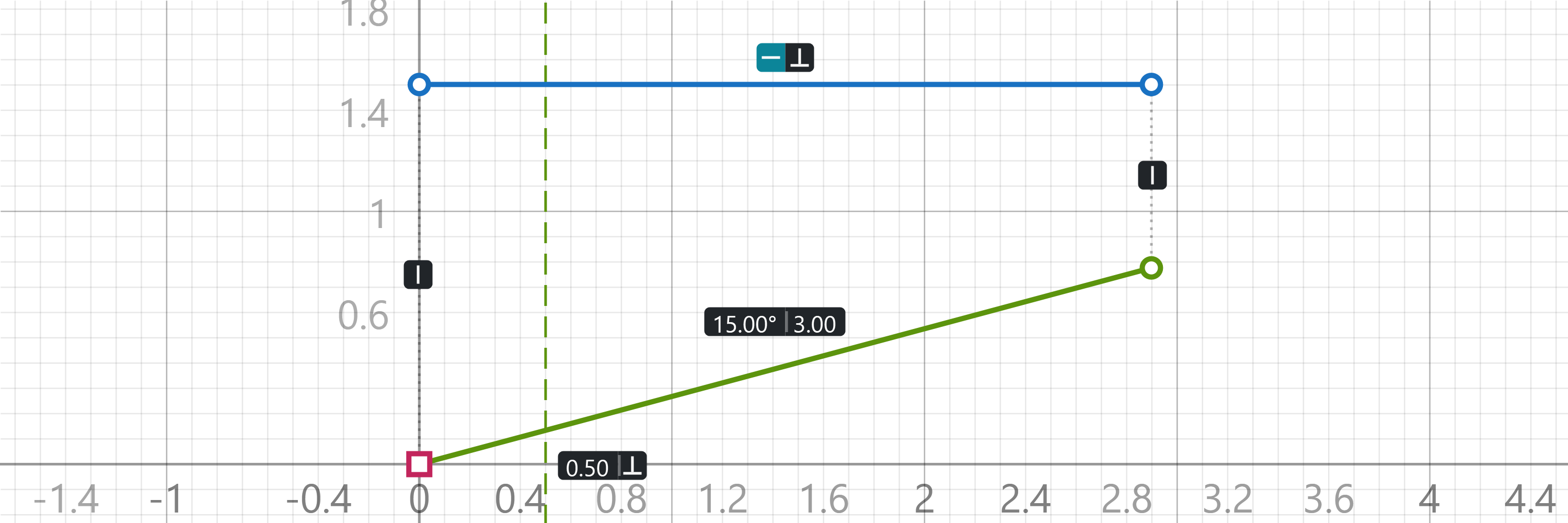
Redundant constraints are usually harmless, but may nevertheless cause problems once the complexity of a system grows. Grasshopper will draw redundant constraints in cyan, though note that a redundancy always involves at least two constraints, and only one of them is marked as such. A redundancy can also span more than two constraints: in a four-sided shape with four perpendicular corners, any one of the perpendicularity constraints is implied by the other three. Which constraint gets marked is arbitrary, so it is up to the user to decide which of the unnecessary constraints to delete.
Conflicts
When constraints conflict, the solver still attempts to provide a least-worst result. It settles on the shape that comes closest to satisfying all constraints, and measures how far off that compromise is. The error is spread across all constraints involved in the disagreement, and since the solver cannot know which of them is wrong, every one of them is coloured red.
Figure 5 shows a conflicted system where what should be a perfect square has edge length constraints of and , which forces almost all other constraints askew as well; the diagonal is no longer at 45°, and parallelism and horizontality are violated too.
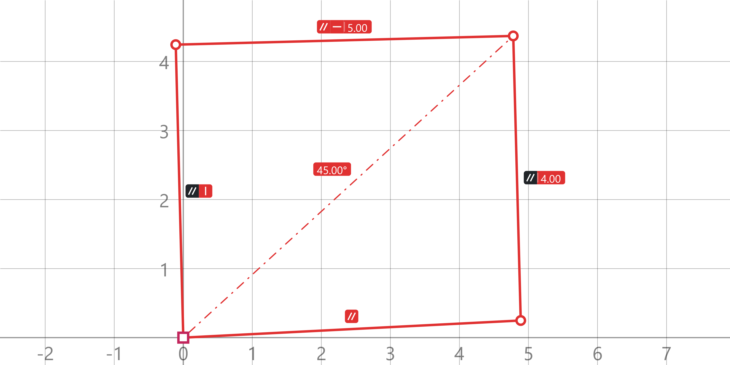
A conflict is usually resolved by deleting or changing one of those constraints, or simply by undoing the last change.
Error Allowance
The amount of error a conflicted system is allowed to have before it counts as a failure is a setting of that system, and it can be changed from the gear menu in the upper-right corner of the editor. The available presets are:
| Setting | Allowed error |
|---|---|
| None | Every constraint has to be met exactly. |
| Small | Constraints may be off by a millionth of the size of the drawing. This is enough to forgive rounding in typed values, but is invisible at any zoom level. This is the default. |
| Medium | Constraints may be off by a ten-thousandth of the size of the drawing, which only shows when zoomed in a long way. |
| Large | Constraints may be off by a hundredth of the size of the drawing, which can be visible and can certainly exceed typical tolerances in Rhinoceros and Grasshopper. |
| Custom | Any value, typed either as a length such as 0.01 or as a percentage of the size of the drawing such as 0.5%. |
Note that "the size of the drawing" is taken to be the median length of the curves in that drawing, and so may change as the system evolves, even if the bounding box of the drawing remains the same.
Fixed Points
A common cause of conflicts is the motion of fixed points. The solver itself never moves a fixed point, but the user is allowed to drag them manually and they can be driven externally via component inputs. It is fairly common for fixed points to be valid only within a local region, and for the system to become unsolvable when a point strays beyond its boundary.
In extreme cases, fixed points are even limited to one-dimensional subspaces. For example, a point may be allowed to exist anywhere along a virtual curve, but cannot be moved away from that curve.
It is basically impossible to limit a manual point drag to the interior of a small, invisible region, let alone a one-dimensional region. To nevertheless allow manual interaction with fixed points in such systems, the Allow fix drift option is available and enabled by default. In this mode, the solver is allowed to pull back a fixed point during a mouse drag to its valid region, if the manual motion yields a conflicted system.
The error allowance setting decides when a drifting fixed point counts as being back in its valid region: the drift stops as soon as the remaining error is within the allowance.