This topic is a reference for all the constraint rules available in the Grasshopper constraint editor; which shapes they can be applied to, what they enforce, and any peculiarities worth knowing about.
Constraints come in two categories; dimensional and relational. Dimensional constraints hold measurements, such as Length, Distance and Angle. Relational constraints meanwhile define interactions between shapes, such as Perpendicular, Tangent or Concentric.
For an overview of constraints and how they are implemented in Grasshopper, see the Constraint Systems topic.
Applying Constraints
Constraints are applied by selecting the shapes they should act on, and then clicking a button in the side panel of the editor or pressing its shortcut key. Note that new shortcuts can be assigned to all tools by right-clicking on the button and typing the new shortcut. Buttons are greyed out while the selection does not allow the constraint.
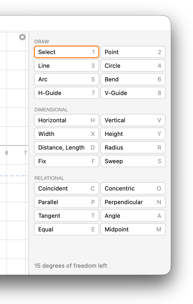
Every constraint is shown as a small tag next to or between the shapes it acts on. Dimensional tags show their value while relational tags show a symbol, as per figure 2.
Valid tags are drawn in black, redundant tags in cyan, conflicting tags in red and selected or hovered tags in yellow. See the Degrees of Freedom topic for more information on conflicting and redundant constraints.
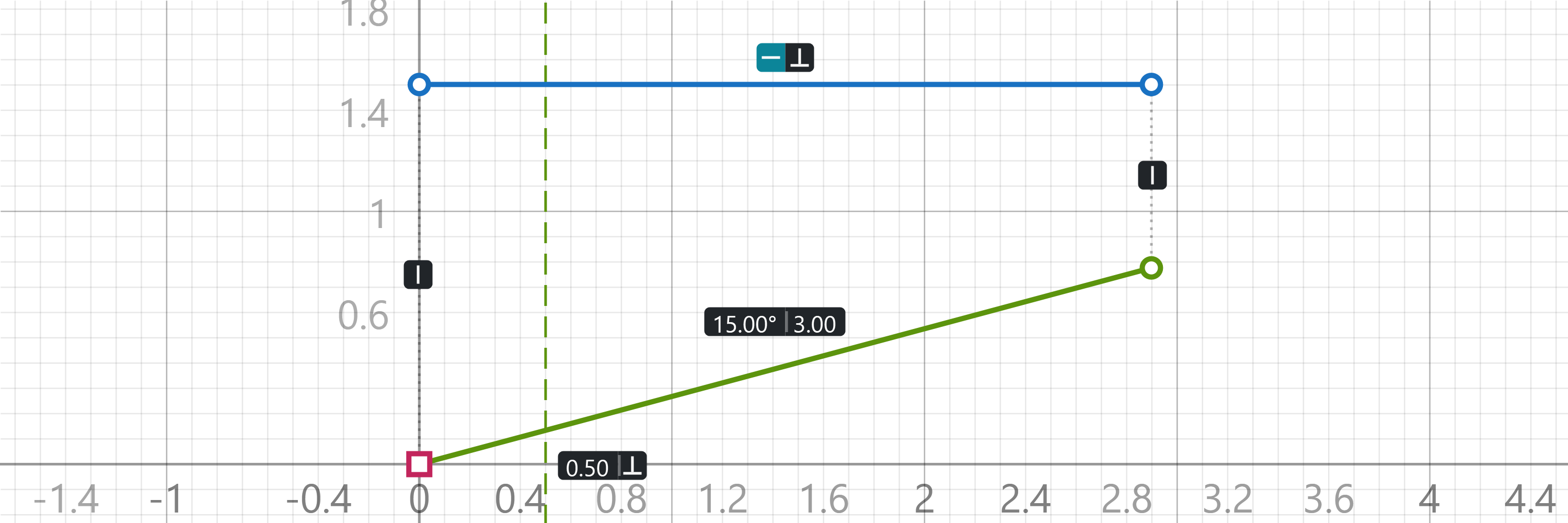
When a dimensional constraint is added to the drawing, it is always given the current value. This way the system does not need to update to incorporate the new dimension. That does mean the initial value is often a very messy number, which may not be reflected in the drawn tag due to the aggressive rounding. A new distance constraint between points which are units apart will nevertheless appear as 4.00 in the editor, since only two decimal places are drawn inside the tags. Always double-click dimensional tags to validate and change the values those constraints are actually supposed to enforce.
Constraint Overview
Table A below lists all the available constraints, along with the object or objects they apply to and the degrees of freedom they remove from the system. When a constraint can apply to different sets of objects, it will be listed more than once.
| Constraint | Application | |
|---|---|---|
| Angle | Single line or guide | |
| Angle | Pair of lines | |
| Angle | Line and a guide | |
| Coincident | Pair of points | |
| Coincident | Point and a curve or guide | |
| Concentric | Pair of non-linear curves | |
| Concentric | Point and a non-linear curve | |
| Distance | Pair of points | |
| Equal | Pair of curves | |
| Equal | Set of curves | |
| Fix | Single point | |
| Fix | Single guide | |
| Height | Single line, or a pair of points | |
| Horizontal | Single line, or a pair of points | |
| Length | Single curve | |
| Midpoint | Point and a line, arc or bend | |
| Parallel | Pair of lines, or a line and a guide | |
| Perpendicular | Pair of lines, or a line and a guide | |
| Radius | Single circle, arc or bend | |
| Sweep | Arc or bend | |
| Tangent | Pair of curves | |
| Tangent | Point where two curves meet | |
| Vertical | Single line, or a pair of points | |
| Width | Single line, or a pair of points |
The remainder of this topic provides additional details for each type of constraint.
Dimensional Constraints
Horizontal and Vertical
Strictly speaking these are not dimensional constraints, as they have no value which can be set. However, they live in the dimensional category because they are special cases of the Height and Width constraints.
The Horizontal and Vertical constraints can be applied to a line, or to a pair of points, even if those points are otherwise unconnected. Holding Shift while drawing a new line automatically assign a Horizontal or Vertical constraint to that line.
Width and Height
Width and Height hold the horizontal or vertical distance between two points, or between the two ends of a line. Unlike Distance, these dimensions exhibit directionality; a width of means the second point lies units to the right of the first, and a width of means it lies units to the left. When the dimension is first added, the points are ordered so that the initial dimension value is positive.
Distance and Length
When applied to a pair of points, the Distance constraint maintains the Euclidean separation between them. When applied to a single curve, the Length constraint maintains the length of the target curve.
Radius
When applied to a circle, arc or bend, maintains the radius of that curve. The Radius constraint is not available for a bend without a bulge, as it would result in an infinite radius constraint.
Sweep
Sweep holds the angle covered by an arc or a bend, in degrees. Arcs always run anticlockwise, so their sweep is between 0° and 360°. A bend with a given sweep may bulge to either side, so a sweep constraint does not stop a bend from flipping.
Note that bends are not able to form into complete circles, so sweep angles very near 360° will not work. Conversely, linear bends all have a sweep angle of 0°, which may also cause problems in the stability of the constraint system.
Angle
Applied to a single line or guide, Angle holds the direction of that line relative to the horizontal axis of the drawing, measured anticlockwise and ranging from −180° to 180°.
When applied to two lines, or to a line and a guide, Angle holds the angle between them. The angle is measured anticlockwise from the direction of the first line to the direction of the second, where the direction of a line runs from its start to its end. When the dimension is first added, the lines are ordered so that the initial angle value is positive.
Fix
The Fix constraint anchors points and guides at their current locations. The solver never moves a fixed point, though they can still be dragged by hand or driven by component inputs. Clicking Fix while all selected points are already fixed releases them again. The origin is inherently fixed and cannot be released.
Naming fixed points is one of the major ways in which Grasshopper can interact with a constraint system. Double-click fixed points to give them a unique name, and that name appears as an input to the component. That input accepts a variety of data types, and the values provided are used to set the location of the fixed point.
| Type | Usage |
|---|---|
Point2 |
Two-dimensional points specify the location of the fixed points in drawing plane coordinates. |
Point3 |
Three-dimensional points specify the location of the fixed points in world coordinates, which are then projected back onto the drawing plane. |
Curve |
Curves specify the location of the fixed points at their intersection with the drawing plane. |
Fixing a guide pins it at its current position, by adding an intercept dimension. This holds where the guide crosses the x-axis for vertical guides, or the y-axis for horizontal guides. Unlike a distance, an intercept constraint can be negative.
Relational Constraints
Coincident
Applied to two points, Coincident forces them to occupy the same coordinates. The Simplify option in the gear menu can be used to actually merge coincident points into a single entity, which makes mouse picks a lot less annoying.
When applied to a point and a curve or guide, Coincident forces the point onto that curve. Though note that coincidence is considered only on the infinitely extended version of each curve. Line coincidence projects onto the infinite line, not the finite segments between the end points. Arc coincidence projects onto the full circle, not the partial arc.
Concentric
Concentric gives two circles, arcs or bends the same centre. This is very similar to the Coincident constraint, except that bends don't have points at their centres.
When applied to a point and a non-linear curve, it creates a coincidence requirement between the point and the centre of the curve.
Concentric constraints involving bends should be used with care. The centre of a bend moves further and further away as the bend straightens, and two straight bends are considered concentric no matter where they are. If a bend needs a well-behaved centre, an arc is probably the better choice.
Midpoint
Midpoint holds a point exactly halfway along a line, arc or bend, measured along the curve. Note that circles cannot participate in midpoint constraints as they have no start or end.
Parallel and Perpendicular
Parallel holds two lines at the same angle, while Perpendicular holds them at right angles. Lines are parallel whether they run the same way or opposite ways. A guide can stand in for one of the two lines, but not for both.
Tangent
The Tangent constraint works in two different ways, depending on whether the curves share an end point. When two lines, arcs or bends meet at a shared end point, Tangent removes the kink at that point, so one curve flows smoothly into the next. Instead of selecting both curves, it is also possible to assign the tangency constraint to the point where they meet.
When the curves do not share an end point, Tangent makes them touch somewhere along their length. At least one of them has to be a circle, arc or bend, and a guide can stand in for a line. A circle can touch another circle on the inside or on the outside, and the solver keeps whichever of the two is closest to the current configuration.
As with Coincident, tangency considers the complete line or circle, so an arc may end up touching a line at a spot which the arc itself does not cover.
Equal
Equal applies to two or more curves at once. When all selected curves are circles, arcs or bends, Equal holds their radii equal. When at least one of them is a line, it holds their lengths equal instead. Selecting curves which are already part of an equal group adds the new curves to that group.
Double-clicking the tag of an Equal constraint allows typing a linear relation instead of simple equality. Typing *1.5 +2 makes the length or radius of the tagged curve one-and-a-half times that of its partner, plus two units. Typing = turns it back into plain equality.