A solved constraint system is a collection of curves, points and measurements, but usually only some of them matter to the rest of a Grasshopper file, and they often matter in different ways. The outline of a plate is needed separately from its holes, and the length of a curved edge may be needed as a number. This topic explains how curves, points and measurements are sent to outputs of the Constraint System component using output codes.
For an overview of constraints and how they are implemented in Grasshopper 2, see the Constraint Systems topic.
The Edges Output
Every Constraint System component has an Edges output, which needs no setting up. It contains all regular curves of the drawing, leaving out points and construction geometry, joined into chains and loops wherever they connect end to end. Sometimes that is all that is needed, but to output only some of the curves, or to output points and measurements or construction geometry, the drawing needs output codes.
Output Mode
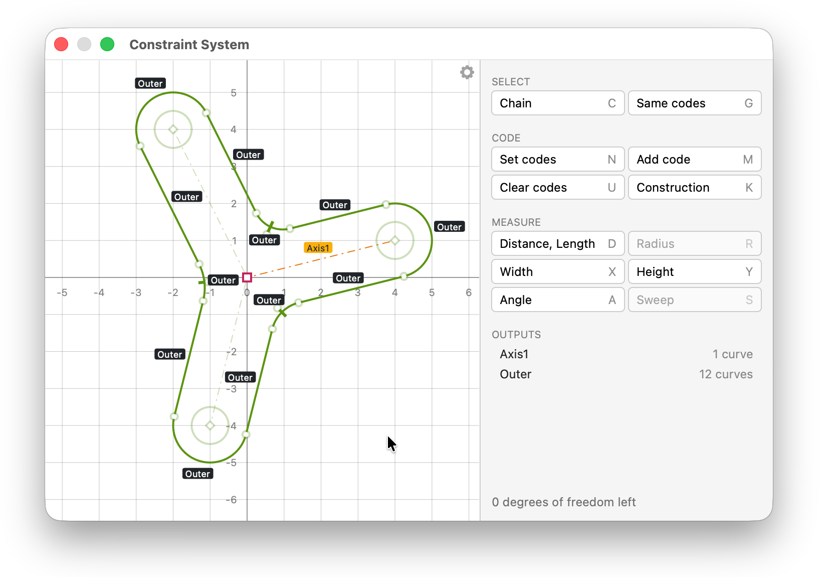
Output codes are assigned in Output mode, which is switched on and off with the Tab key or from the gear menu. In Output mode the drawing tools and constraint tags are hidden, curves and points without a code are faded out, and every coded curve or point shows a label. No geometry or constraints can be added or deleted in this mode.
The side panel in Output mode has three groups of buttons and a list of all codes in the drawing.
| Button | Effect |
|---|---|
| Chain | Grows the selection to include all curves connected to the selected ones. |
| Same codes | Grows the selection to include everything that shares a code with the selection. |
| Set codes | Replaces the codes of all selected curves and points. |
| Add code | Adds codes to all selected curves and points. |
| Clear codes | Removes all codes from the selected curves and points. |
| Construction | Switches the selected curves between regular and construction geometry. |
| Distance | Adds a distance measurement. |
| Radius | Adds a radius measurement. |
| Width, Height | Adds an axis-aligned distance measurement. |
| Angle | Adds an angle measurement. |
| Sweep | Adds an arc sweep angle measurement. |
Output Codes
An output code is a short name such as A, Holes or rim_2. Like input names, codes must start with a letter or an underscore, and may contain only letters, digits and underscores. Codes are typed into a box which opens after clicking Set codes or Add code, or after double-clicking a curve, point or label. Several codes can be assigned to a single object if they are separated by commas.
Every code in the drawing becomes an output on the component, named after the code. Outputs are sorted by code, and they appear and disappear as codes are added and removed.
Curves
All curves with the same code are outputted together. Curves which connect end to end are joined into chains, and chains which close up are outputted as closed loops. Chains stop at points where three or more curves meet, since there is no way to know which way to continue.
A curve can carry several codes, in which case it appears in several outputs. Construction curves can be given codes too, which is the only way to get them out of a constraint system.
Points
All points with the same code are outputted together as points. Points stacked on the same spot share their codes, so a corner where two lines meet is outputted only once.
Measures
A measure is like a dimensional constraint, except that it does not affect the shapes it is attached to. It only reads a value from the solved drawing and sends it to an output. Measures are added with the Measure buttons in Output mode, and they accept the same selections as the corresponding dimensions in Drawing mode, which are described in the Constraint Rules topic. The box for the output code opens as soon as the measure is added.
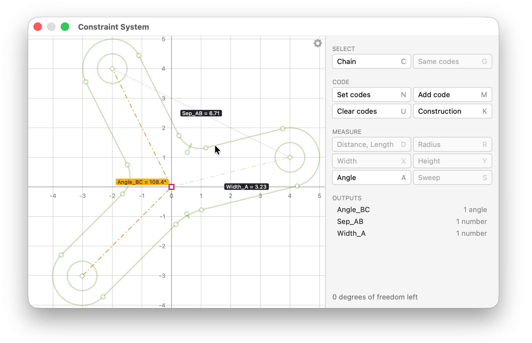
Distances, lengths, widths, heights and radii are outputted as numbers, angles and sweeps as angles. Measures only show while the editor is in Output mode.
Mixing Kinds
A single code can only be used for things of the same kind: curves, points, lengths or angles. Giving a curve and a point the same code is an error, since the output would not know whether it is a curve output or a point output. The editor refuses such codes when they are typed, and the component reports a code conflict if one occurs anyway.
Renaming and Selecting Codes
The list at the bottom of the side panel shows every code in the drawing. Hovering over a code highlights everything that carries it, clicking a code selects all the curves, points and measures that carry it, and double-clicking a code allows it to be renamed. A code can also be renamed by double-clicking it inside a label in the drawing.
Renaming a code renames the matching output on the component, without breaking any wires attached to it. This only works when the renamed code still covers exactly the same curves, points or measures; otherwise the component treats it as a new output.
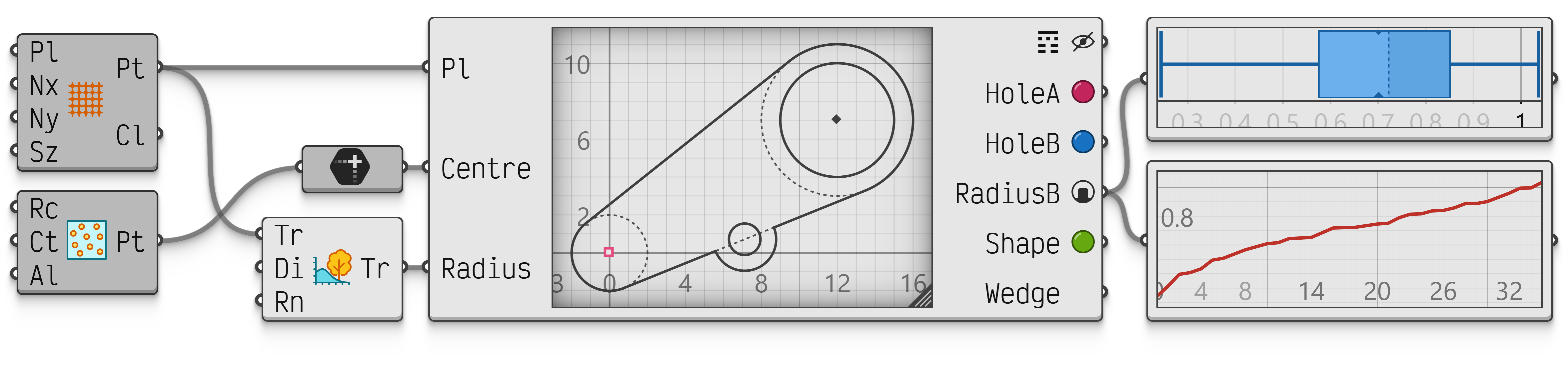
The example file below shows how to drive a constraint system with Grasshopper values, how to generate a bundle of different configurations for a single system, and how to tweak the outputs to contain specific shapes and measurements.
 Interactive in Grasshopper 2