1. Modeling Vocabulary

 |
Overview of what 3D modeling means and what are the general components of 3D modeling vocabulary |
3D modeling is the process of using computers to create, visualize, edit, and share three-dimensional forms. Computers use geometry as the primary conduit to represent design form and use data to attach information to geometry. Most 3D modeling applications share common vocabulary; the first step to learning how to model within any environment is understanding its vocabulary. That includes workspace organization, access to different tools, modeling controls, what geometry is supported, how it aggregates, and how data is applied and managed. Visualization, analysis, and presentation of 3D forms are also integral to modeling applications. Models are stored and exchanged using files, and file formats are either specific to the application or more widely used across multiple ones. This chapter discusses the modeling vocabulary in Rhino.
1.1 The workspace
1.1.1 User interface
 |
Rhino workspace... |
Once you open the Rhino application, you will see a screen with a graphic area in the center (viewports) surrounded by menus, toolbars, controls, and panels. Most of the workspace elements can be rearranged, removed, or expanded.
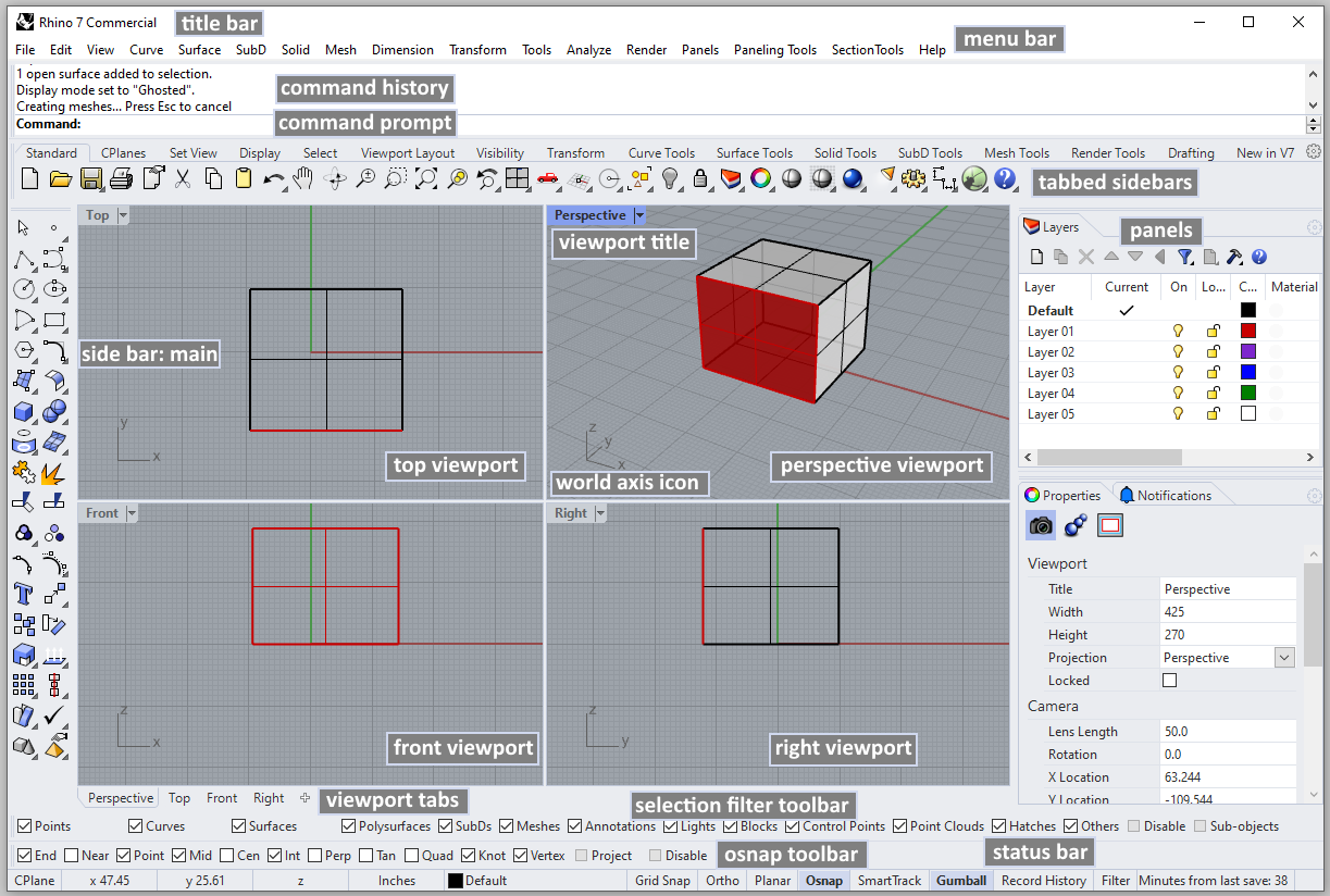 User interface elements include:
- Title Bar: Displays the filename and the Rhino version used.
- Menu Bar: Access commands, options, and help through text-based drop-down menus.
- Command Prompt: Area to type and run commands, and see options and other information displayed by the command while running or after it exits.
- Command History: Displays the most recently used commands and all their prompts.
- Tabbed Toolbars: Groups are containers with one or more toolbars, with a tab at the top for each toolbar.
- Sidebar: Toolbar to access common commands and options related to the selected tabbed toolbar.
- Tabbed Panels: Rhino controls such as layers, properties, materials, lights, display mode, and help are displayed in panels with tabs. Tabbed panels can be arranged side by side, or vertically.
- Layer and Property Panels: Two important panels that can be tabbed. Most users have at least these two panels visible.
- Status Bar: Displays the coordinates of the pointer, the units, and the current layer of the model, toggles, and other options.
- Osnap Toolbar: Used to set object snap settings.
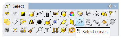
- Selection Filter Toolbar: Used to narrow down what geometry can be selected.
- Viewport Tabs: Click to make active a viewport. Also, use the “+” to add more viewports and Layouts (paper space).
- Standard Viewports: Displays different views of the model within the graphics area. Viewports can show a grid, grid axes, and world axes icon. Any number and combination of viewports can be arranged within the graphic area. The default viewport layout displays four viewports (Top, Front, Right, and Perspective).
- Viewport Title: Display the viewport projection. Click the arrow to access viewport settings through the drop-down menu.
- Gridlines and Axes: Used to aid modeling. Their visibility, colors and other settings can be customized.
- World Axes Icon: Used to aid modeling. It changes when rotating the model.
1.1.2 Help
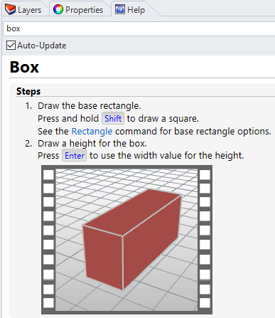
The help files include the full functionality of the modeling application. Rhino help is accessible online and also from within the application using Command Help. Topics are displayed in a dockable panel. The help offers detailed descriptions of the commands, options, and short videos that show the workflow. If you check the Auto-Update option in the command line, the help topic updates for the current command. To access the entire Rhino help document in a browser window, go to Help > Help Topics menu, or press F1.
1.2 Viewports and Navigation
1.2.1 Viewports
The 3D modeling space is contained inside special windows called viewports. You can think of viewports as cameras looking at the same model from different angles. Furthermore, you can set viewports to parallel, isometric, or perspective projection. To assist modeling, each viewport includes an origin point, coordinate axes and a grid drawn on a default plane called construction plane. You can think of a construction plane as the default plane where geometry is drawn unless coordinates are typed in (relative to world coordinate) or if snapped to some other geometry.
Each view in a viewport is seen through a camera lens. The invisible target of the camera is located in the middle of the viewport. You can assign different projection, zoom, and camera angles for each of the viewports as needed. To change your view:
- Click on the arrow next to the viewport title.
- Select Set View submenu.
- Choose your preferred view.
You can also access these steps from the command line using the SetView command.
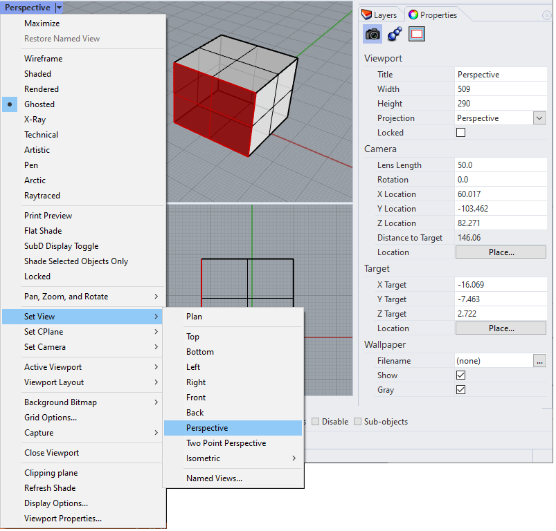
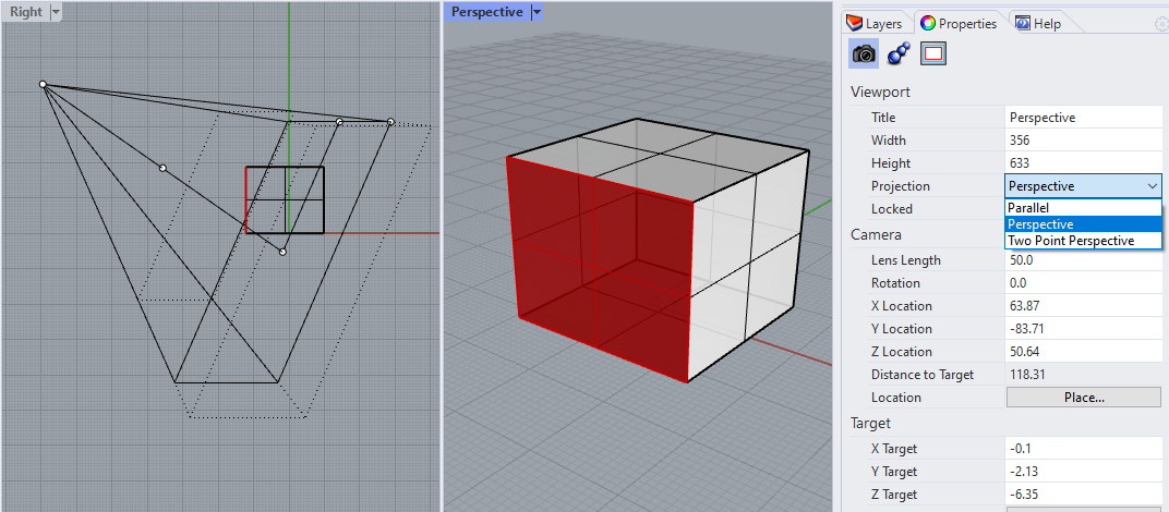
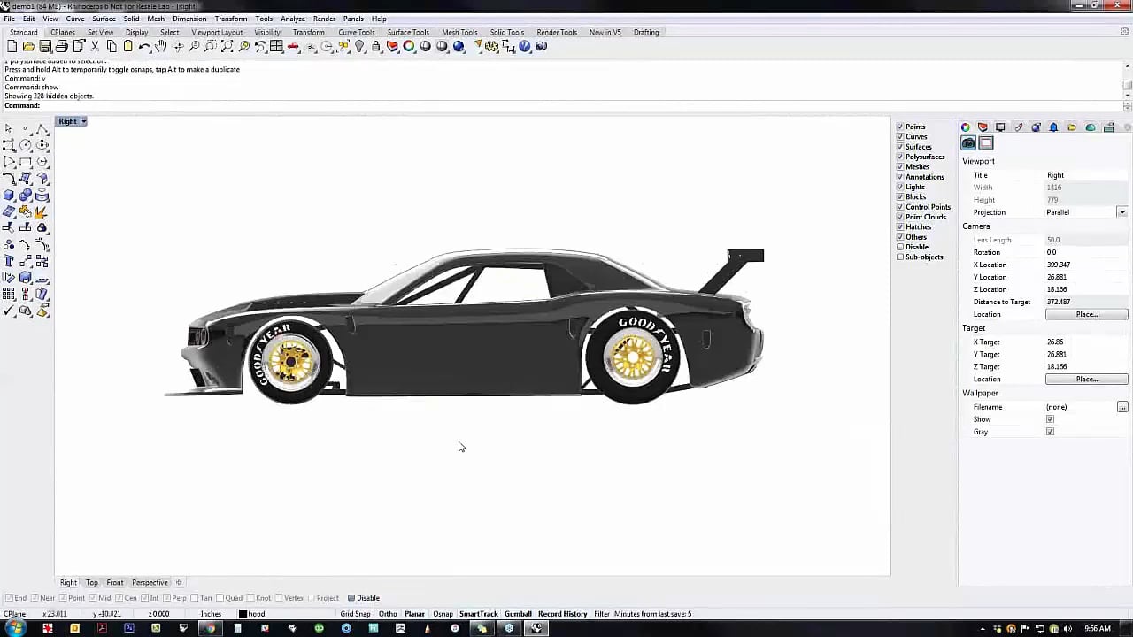
The property panel shows the viewport settings and camera location. You can adjust the projection of a view directly from the property panel. You can also adjust the camera location and target. You can visualize the camera and edit interactively. You can run the Camera command and toggle the view.
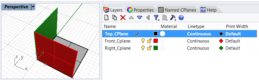
You can customize the viewports and their position to suit your preferences. The position of viewports is adjustable. To move and resize viewports, drag the viewport title or borders. You can create new viewports, rename them, and use predefined viewport configurations. To toggle between a small viewport and one that fills the graphics area, double-click the viewport title. You can display the viewport titles in tabs if you prefer. The highlighted tab designates the active viewport. Tabs make it easy to switch between viewports when using maximized or floating viewports. One unique feature about Rhino is that each of the standard four viewports has a different construction plane (except perspective, which uses the Top CPlane by default).
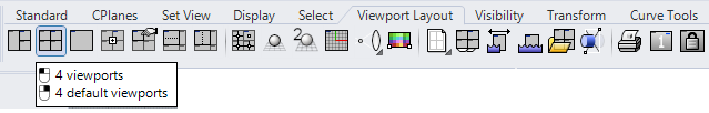
With Rhino, you can open an unlimited number of viewports. Each viewport has its own projection, view, construction plane, and grid. If a command is active, a viewport becomes active when you move the mouse over it. If a command is not active, you must click in the viewport to activate it. You can divide your viewport to have multiple viewports with different projections from Viewport Layouts, then split it horizontally or vertically. You can go back to the standard four views.
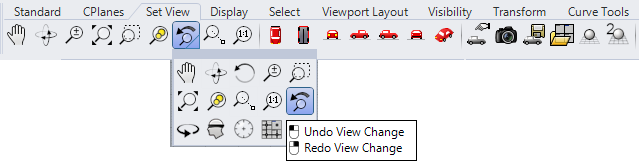
There are designated commands to undo and redo view changes. Click in a viewport, press your Home or End keys on your keyboard to undo and redo view changes, or click on undo-redo view changes under the Set View tab in the toolbars.
1.2.2 Navigation
Navigating modeling space refers to the ability to reach certain parts of your model and view them up close or from far at any angle and projection. Terms such as “zoom,” “pan,” and “parallel projection” are standard in all modeling software. The computer mouse is usually used to navigate models, along with specialized commands or tools to help quickly get around. Screen gestures and virtual reality tools allow navigating touch screens and VR.
View navigation includes panning, zooming and orbiting. Panning means shifting the view without changing the camera angle. Rhino Pan command supports panning at any projection. The simplest way to pan is to drag the mouse with the right mouse button held down (if you are in perspective, you also need to hold down the Shift). To zoom in and out, use the mouse wheel or hold down the Ctrl key and drag your mouse up and down with the right mouse button held down. Orbiting is only active in perspective views. With the right mouse button down, moving the mouse rotates the view around the center of the view (or the target of the camera). You can pan, zoom, or orbit your view in the middle of any command to see precisely where you want to select or snap.
Here is a quick reference to the mouse actions and corresponding effect in Rhino:
- Right mouse button: Repeat the last command or end a current command
- Left mouse button: Selects objects
- Press wheel: Customizable Pop-up menu
- Drag with the right mouse button down: Orbit the perspective viewport and pan parallel viewports
- Shift + Drag Right mouse button: Pan perspective viewport
- Roll the wheel: Zoom in and out
- Ctrl + Right mouse button: Zoom in and out
1.2.3 Viewport navigation tutorial

 |
1.2.3 Tutorial handout... |
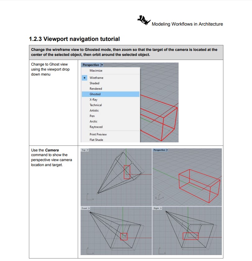
Change the wireframe view to Ghosted mode, zoom so that the target of the camera is located at the center of the selected object, then orbit around the selected object.
1.3 Access to commands
 |
Commands access... |
Commands are actions or functions that perform specific operations. For example, Circle is a command that helps create and add a circle to the 3D model. Rhino allows invoking the same commands using many different ways, such as command-line, menus, toolbars, or interactively through widgets, mouse and keyboard events. For more advanced access, Rhino supports creating custom commands through macros and scripting. The different ways to access Rhino commands mean that you have the flexibility to choose the method you are most comfortable with to help increase your productivity. Each command has a name, and most commands allow setting various options.
1.3.1 Command-line
Command-line is a widely used method to access commands in Rhino, especially among users familiar with the commands they commonly use. Commands are run by typing their names (or the first few letters of it) in the Command Prompt. Typing in the command prompt shows a list of all commands starting with the same letters. Frequently used commands are shown at the top of the auto-complete list. Right-mouse-click on the command line to view recently used commands. You can also press Enter to run the last command (or right-mouse-click or space key) and press Esc to cancel a running command. When inside a command, the command prompt area shows the command instructions and options. Many Rhino commands do not support dialogs; hence, command options can only be set through the command prompt area.
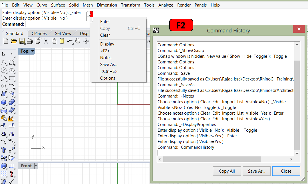
The command history area shows recent commands and options used. You can press F2 to view the command history and all the options used. Right-mouse-click on the Command prompt area shows a menu with all recent commands used that you can select directly from to repeat.
1.3.2 Toolbars
Rhino toolbars contain buttons that provide shortcuts to commands with various options. You can float a toolbar anywhere on the screen or dock it at the edge of the graphics area. Rhino starts up with the Standard toolbar group docked above the graphics area and the Main toolbar as the sidebar on the left.
Tooltips
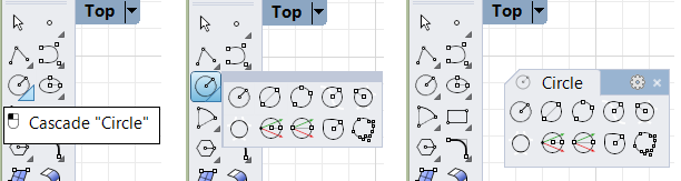
Tooltips tell what each button does. To access the tooltip, move your pointer over a button without clicking it, and a small tag with the name of the command appears. In Rhino, buttons can be set to execute multiple commands and set specific options. The tooltips also indicate which buttons have dual functions, as in the following example.
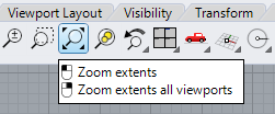
Cascading toolbars
A button on a toolbar may include other buttons in a cascading toolbar. Usually, the cascading toolbar contains variations of the base command. After you select a button on the cascading toolbar, the toolbar disappears. A small black triangle in a button’s lower right corner indicates cascading toolbars. To open the cascading toolbar, hover over the black triangle and left-mouse-click. You can select a button from the cascade toolbar, or peel it out by clicking on the top margin of the toolbar.
1.3.3 Menus
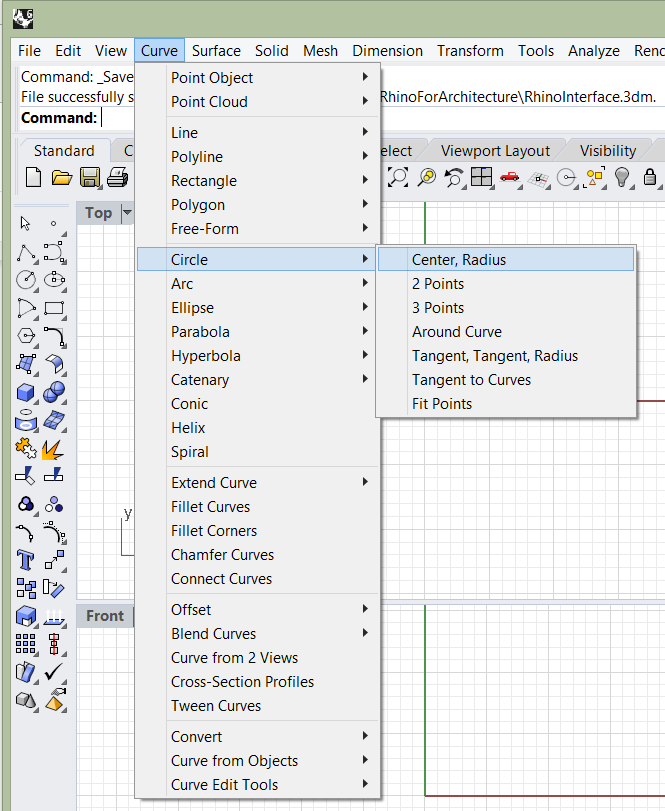
You can find most Rhino commands in the menu bar. Each menu groups similar commands together. There are many submenus within each drop-down menu to further group similar functionality. For example, the Curve menu includes curve creation and editing commands. Under Circle, you can see all the different ways to create a circle. Third-party plugins sometimes add their menus to the menu bar.
1.3.4 Custom access
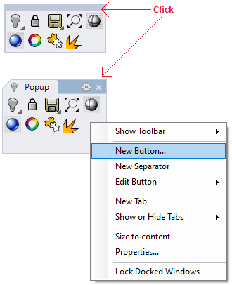
There are a few ways to customize your access to Rhino commands. The main objective is to increase productivity for repeated commands and sequence of commands. The pop-up menu is accessible when you press the wheel (or middle mouse button). It is an on-demand toolbar where you can add or remove buttons or create your own custom buttons with custom macros. For details about how to customize toolbars, check the toolbars help topics.
The context menu appears when you press the right mouse button for a second and release it. You can add to it additional commands that are readily accessible with mouse control.
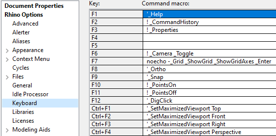
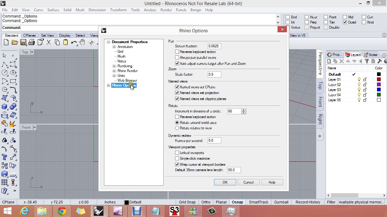
You can set up a custom keyboard access. Rhino comes with a few preset keys the user can edit. For example, F1 opens the Help, Ctrl+S to Save and Ctrl+Z to Undo. You can find the complete list under the Rhino Options under the Keyboard section (open by running the Options command).
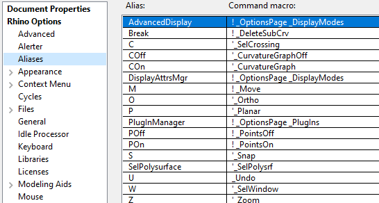
Aliases allow setting custom command names to run existing commands and macros. Macros allow setting one or more commands with specific options to run all at once. Rhino has a few preset aliases, such as ZE for Zoom with Extents option and M to Move. You can change and add to the list of aliases, save them, and share them with other users.
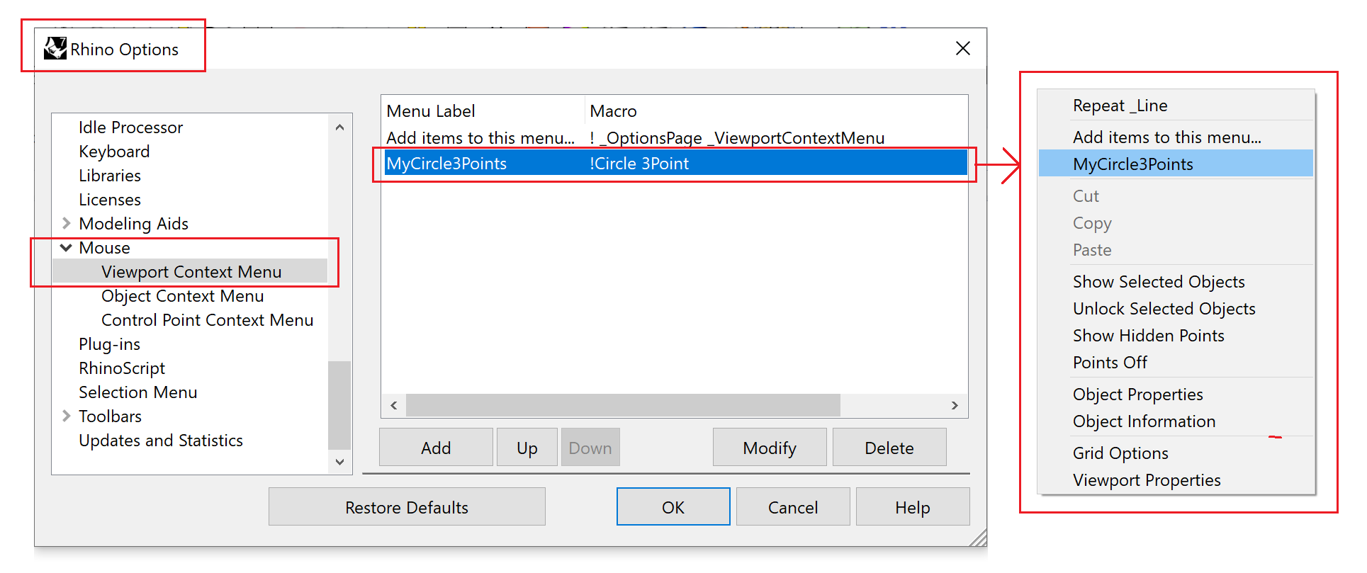
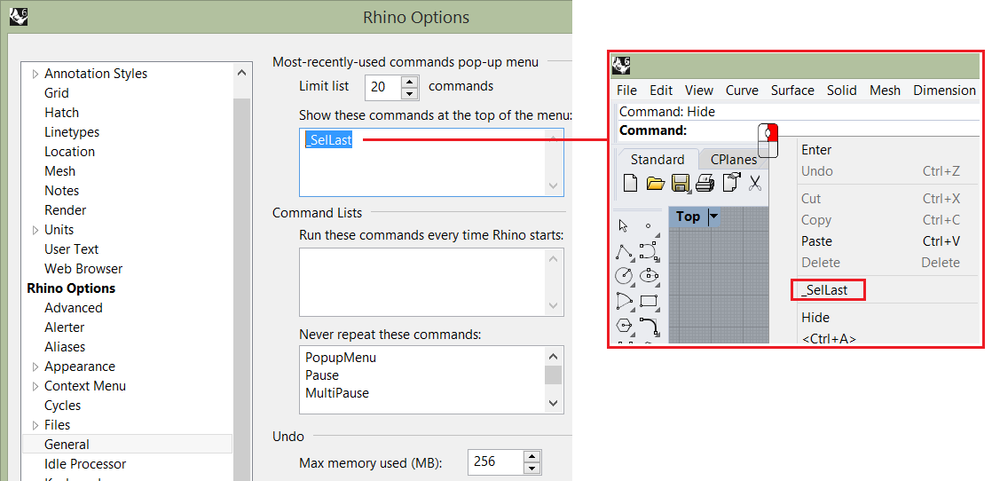
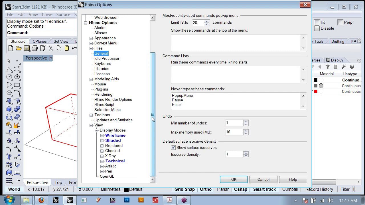
Most recently used commands are accessible when you right-click on the command area. You can add your choice of command at the top of the list by setting the Rhino options > General, then enter your command macro in the top field as in the following image.
1.3.5 Commands access tutorial
 |
1.3.5 Tutorial handout... |
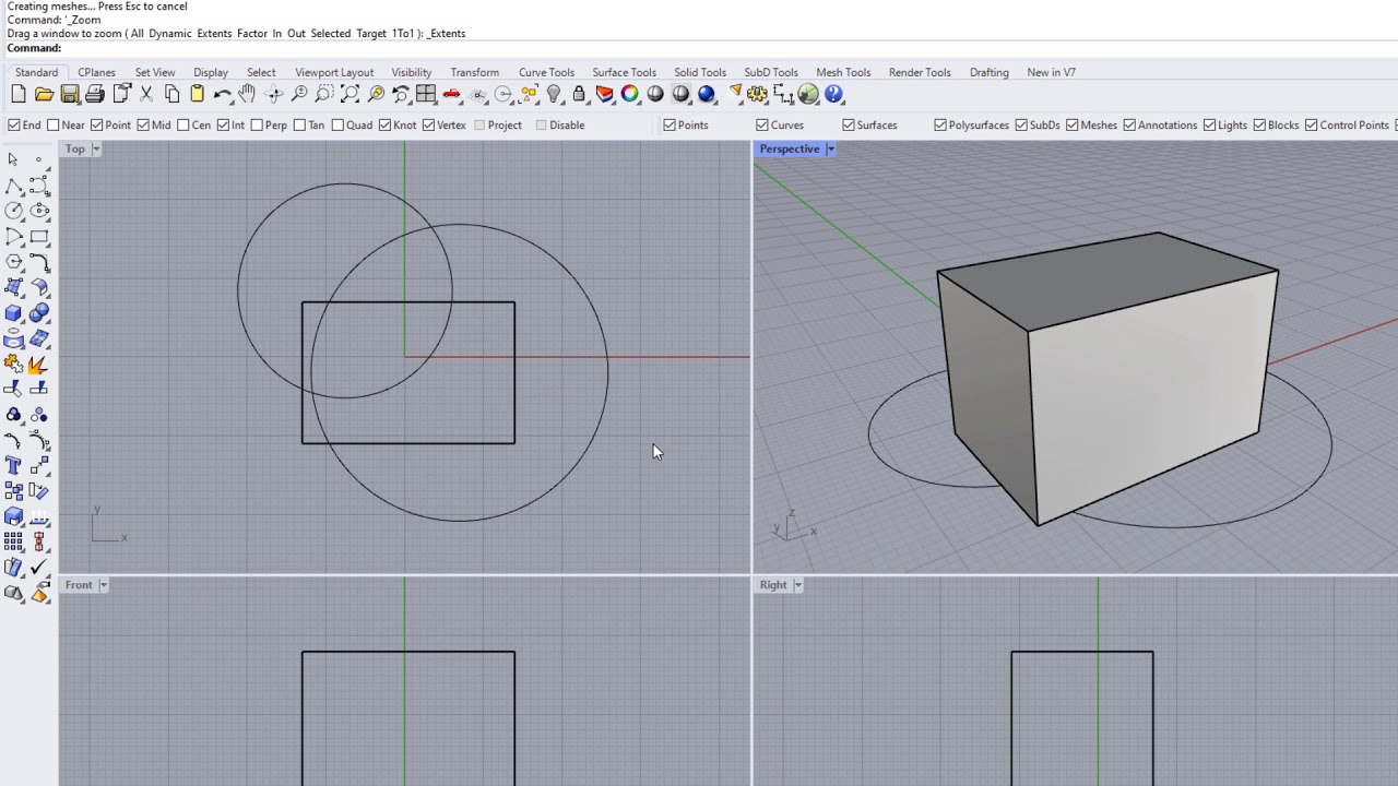
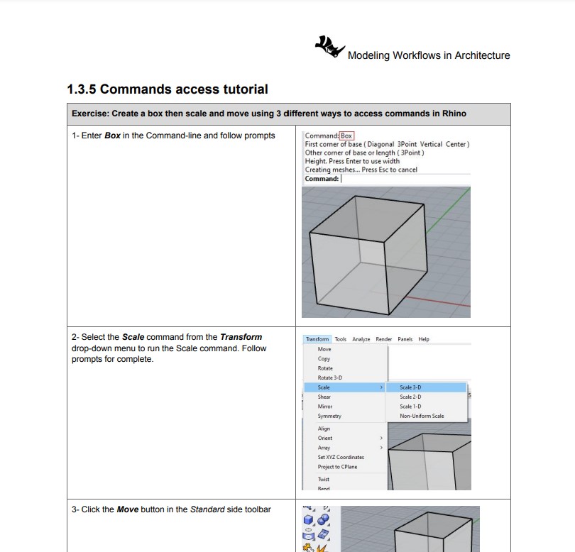
Create a box, then scale and move it using three different ways to access commands in Rhino.
1.4 Modeling aids
Interactive digital 3D modeling can be challenging without guides, constraints, and ways to organize and manage geometry and data. Modeling aids help locate and manage 3D geometry. Modeling guides include grids, coordinate axes, and smart tracking mechanisms. Constraints include ortho, geometry constraints, filters, selection constraints, gumball, and construction planes. Layers help organize geometry and assign some attributes. Geometry in Rhino also has attributes that can be managed using the properties panel. You can set document and application preferences in the Rhino document properties and options. We will cover the most used parts in the following sections and the rest of the document, and you can reference the full details in the Rhino help file.
1.4.1 Grid and grid snap
Grids are a handy visual reference of the modeling spaces’s orientation and scale. You show, hide, and change the number of grid lines, spacing, and intervals in which you can snap to.
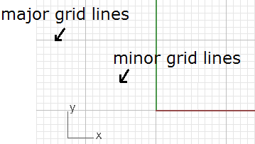
Grid Snap helps snap on grid intersections. You can also toggle Grid Snap on and off by pressing F9 or typing the letter S and pressing Enter. Pressing F7 hides or shows a reference grid in the current viewport of the graphics screen at the construction plane.
1.4.2 Osnap
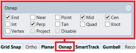
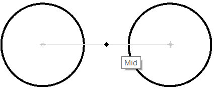
Object snaps constrain the marker to an exact location on an object such as the end of a line or the center of a circle. These are essential tools to help model accurately and quickly. You can customize Osnap to follow one or more constraints. To quickly use only one constraint, right-click on it to disable the others. Another right mouse click on it will restore the previous Osnap state. One special Osnap is Project. If checked, your geometry will be projected to the view construction plane even if you snap outside of it.
1.4.3 Smart Track
Smart Tracking uses temporary reference lines and points that are drawn in the Rhino viewport, using implicit relationships among various 3D points, other geometry in space, and the coordinate axes’ directions. Smart Track uses OSnap settings to create the reference lines.
It is also possible to set up persistent modeling guides that appear when selecting points. Use AddGuide and RemoveGuide to add and remove these guides.
1.4.4 Selection
Rhino supports different ways to select geometry. Selection commands allow selecting all objects in the file that are of a certain type or share certain attributes.
A cross or box window selection is used to select geometry by dragging the mouse (with the left button down) around a specific area inside a viewport.
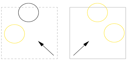
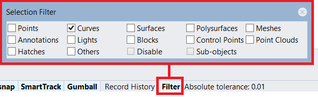
The selection filter allows isolating certain object types. The window selection then selects only the types permitted by the selection filter. For example, if only “Curves” is checked, then no other object type is selected, even if they fall within the window.
1.4.5 Gumball
 |
Gumball overview... |
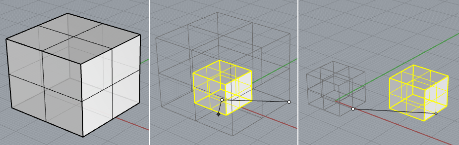
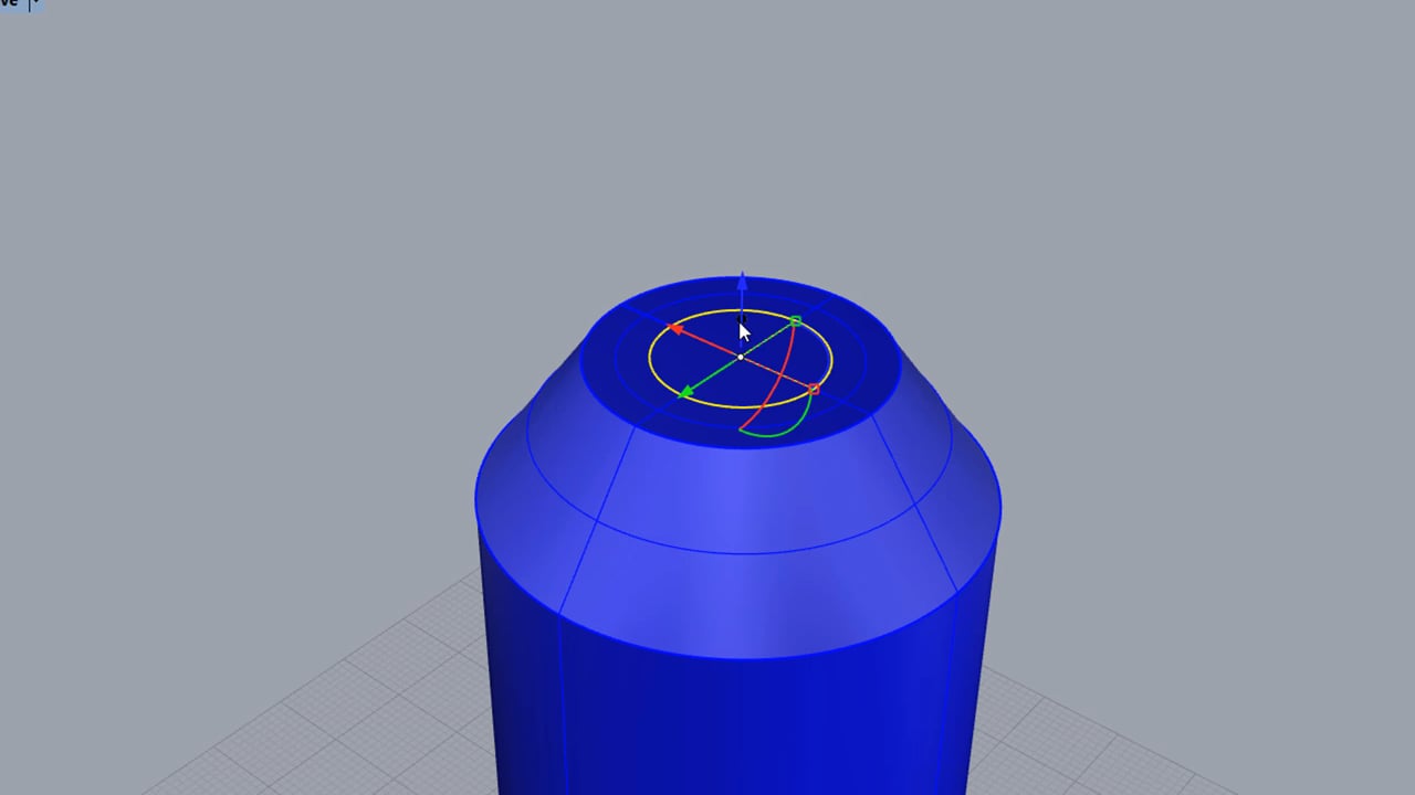
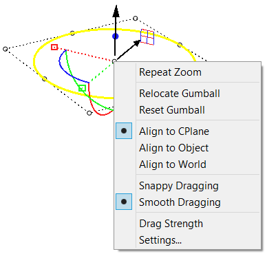
Gumball displays a widget on a selected object which is used to facilitate direct editing. It provides move, scale, and rotate transformations around the Gumball origin.
Dragging Gumball arrows move the object in the arrow direction. Note that pressing the Alt key makes a copy of the object.
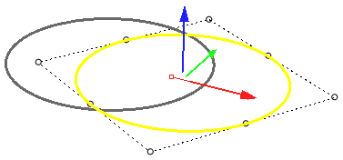
Moving the Gumball handles scales the object in the handle direction. If dragged with the Shift key down, the scale becomes uniform in both directions
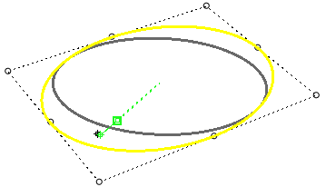
Dragging Gumball arcs rotate the object.
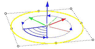
Dragging the arrow handle extrudes the object. With Shift, it extrudes in both directions.
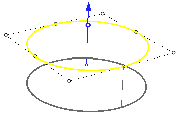
Access other Gumball functions with a right mouse click at the center handle.
1.4.6 Layers
Layers are important to organize and access objects in the document and are used by most modeling software. You can assign meaningful names to layers and set common attributes such as colors and materials. You can quickly hide, lock or select the objects in any layer, and move objects between layers. For details about the different parts of Rhino layers and related commands, please refer to the layers section in the help.
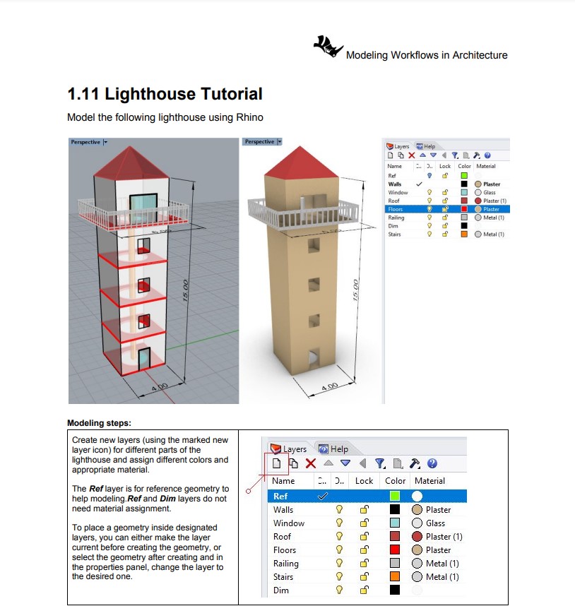
Default layers with new document using one of the Rhino templates: Multiple layers are created with different colors. Default is the designated current layer (new objects are placed in the current layer). No material is assigned.
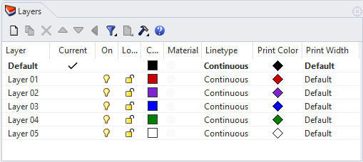
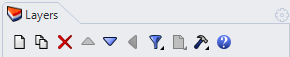
Layer table functions are used to manage layers (add new layer or sublayer, delete, move within the table, filter, and other functions.
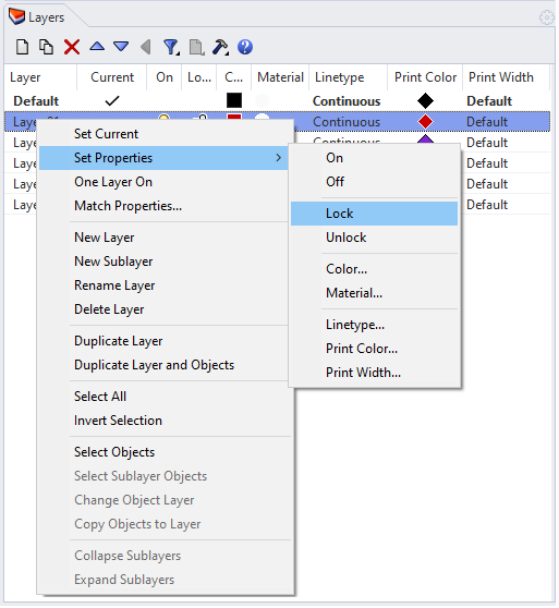
Right mouse click on any layer shows all commands related to the selected layer. For example, you can set it as the current layer, change any property, create a sublayer, or select all the objects within that later.
1.5 Coordinate system
1.5.1 Overview
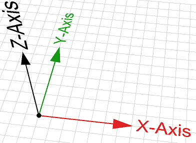
The coordinate system is used to describe the location of points in space. The most common one for architectural applications is the Cartesian coordinates. Rhino uses two Cartesian coordinate systems: world coordinates and construction plane coordinates. World coordinates are fixed in space, while construction plane coordinates are defined for each viewport. Rhino also follows the right-hand rule to define the relative directions of the X, Y, and Z axes directions. That means when the right-hand thumb points in the positive x-direction and the forefinger points in the positive y-direction, then the middle finger points in the positive z-direction. Also, if the thumb is pointing in the Z direction, rotating towards the fingertips points to the positive angle direction. Three World planes (XY, XZ, and YZ) meet at the origin point. The location of any point in space is described with three ordered numbers (tuple). The World origin is located at (0,0,0). Points in Rhino can be defined in either absolute or relative coordinates. You can also use polar notation to describe a point.
The following examples show how to specify points coordinates in Rhino relative to the construction plane and world coordinates.
- Construction plane coordinates: Enter x,y,z values to place points relative to the current construction plane. You may omit z and y values (they are set to 0 in this case). Examples:
0 = (0, 0, 0) in CPlane coordinates
1,3.5 = (1, 3.5, 0) in CPlane coordinates
1,3.5,6 = (1,3.5,6) in CPlane coordinates - World coordinates: When the construction plane is different from the World planes, you need to specify that your point is relative to World coordinates by preceding the x,y,z with “w”. Examples:
w0 = (0, 0, 0) in World coordinates
w1,3.5 = (1, 3.5, 0) in World coordinates
w1,3.5,6 = (1,3.5,6) in World coordinates\ - Polar coordinates: Use distance, angle, and z value (from CPlane origin). Examples:
17 < 45 (radius < rotation angle) 17 < 45,8 (radius < rotation angle,z) - Relative coordinates: This helps locate a point relative to the last point used.
Suppose last point used was (1,1,0):
@3,4 = 4,5,0 (move 3 units in the x direction and 4 units in the y direction from the previous point).
Alternatively, use “R” or “r” instead of “@” to express relative coordinates:
R3,4 (or r3,4)
You can also use relative polar coordinates:
r4 < 45 or @4 < 45
1.5.2 Construction planes
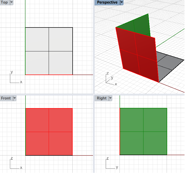
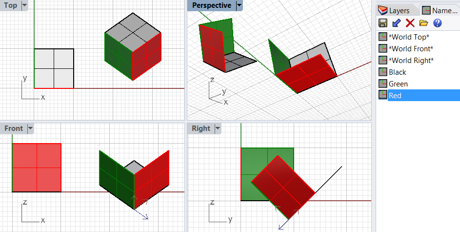
Construction planes (CPlane) are used in modeling software to orient and guide modeling. They align to the World origin and direction by default but can change to be relevant to the model. Creating moving and viewing geometry in Rhino is highly influenced by the orientation of the construction planes. For example, points you create always land on the construction plane unless you use coordinate input (key in as text), use elevator mode or object snaps.
Rhino default parallel views have their own construction plane parallel to the view itself but they share the World origin. Perspective view uses the World Top construction plane.
Rhino supplies a rich set of commands to realign the construction plane and synchronize other viewports to follow if needed. If your model has specific directions that you need to use often, then you should save them in the named construction plane table. This way, you can reference them quickly and not have to recreate them every time you need them.
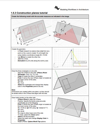
1.5.3 Construction planes tutorial
 |
1.5.3 Tutorial handout... |
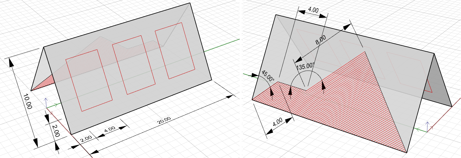
Create the following model using the accurate measures indicated in the image.
1.6 Geometry
Modelers support various geometry types. The most common types are NURBS and polygon meshes. NURBS, the primary geometry type in Rhino, enables high-precision free-form modeling in very small tolerances. The following is a quick, practical overview of key concepts. For details about NURBS geometry, refer to Chapter 3 in the Essential Mathematics for Computational Design.
1.6.1 NURBS geometry
Rhino uses NURBS curves and surfaces as its primary method to represent geometry. NURBS is an accurate mathematical representation of curves that is highly intuitive for creating and editing free forms.
NURBS Curves
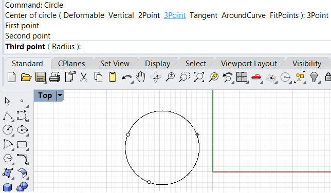
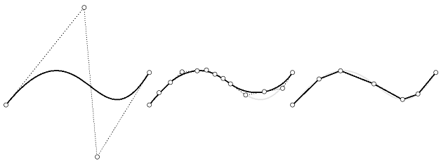
When representing curves using NURBS, the control structure makes editing easy and predictable. The control structure of a curve consists of a list of points used to construct and edit the curve. The Rhino Curve command draws a NURBS curve by default. For example, here are the steps to create a curve.
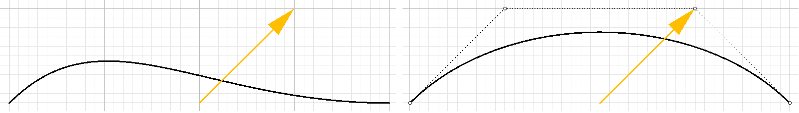
At any point after you create the curve, control points can be turned on (use the PointsOn command) and dragged to adjust the curve interactively (use the PointsOff command, or Esc to turn off control points when done), as in the following.
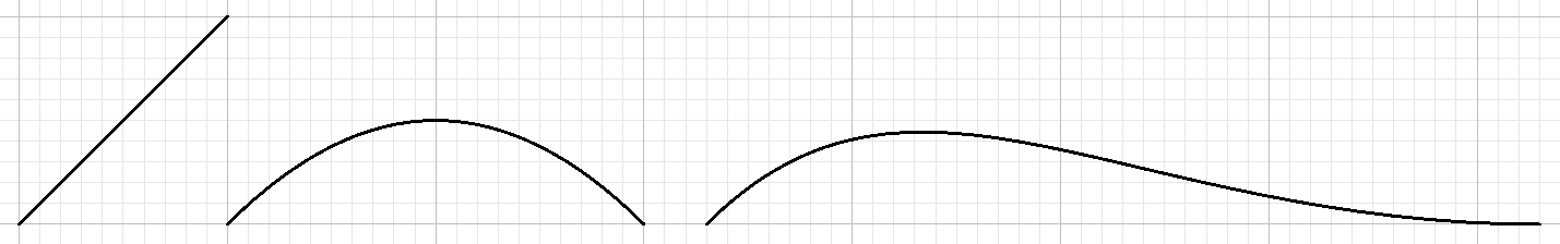
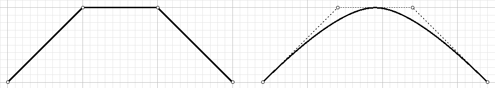
Other than control points, you need to pay attention to the curve degree. The degree determines how smooth a curve is. In simple terms, degree 1 creates polylines, degree 2 creates arcs, and degree 3 creates smooth curves. Higher degrees simply increase the smoothness and are not very commonly used. The curve degree in the example above is set to 3 (the default when you run the Curve command), but you can change a degree option. Here is how our curve looks when set to degrees 1 and 2 using the same control structure.
It is possible to join two curves together if their end points coincide. The new curve is called polycurve (or polyline if it consists of lines).
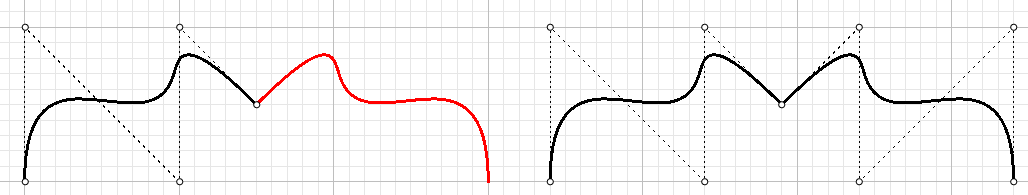
Notice that joining smooth NURBS curves together creates a “kink.” Deleting the control point directly on the kink fixes the curve continuity, but you can also join curves smoothly using commands such as BlendCrv.
NURBS surfaces
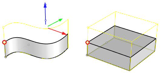
Surfaces in Rhino are created using NURBS. You can think of them as a network of NURBS curves in two directions. They are infinitely thin, infinitely flexible, mathematically defined digital membranes. Surfaces are represented on screen by either some outline curves plus some interior curves called isocurves, or by a shaded picture which makes a surface appear to have some substance. How surfaces are painted on the screen is dependent on the display mode in the viewport, and does not affect the surface NURBS structure in any way. The important thing to remember about surfaces is that they are defined with great precision at every point. They are not approximations.
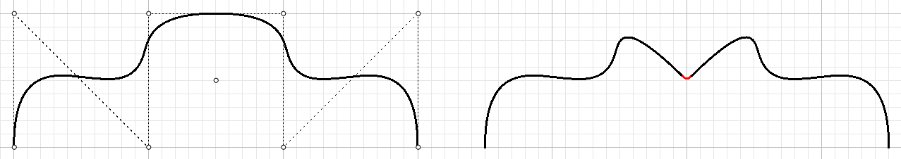
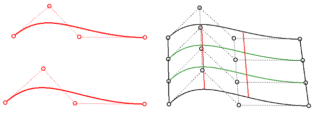
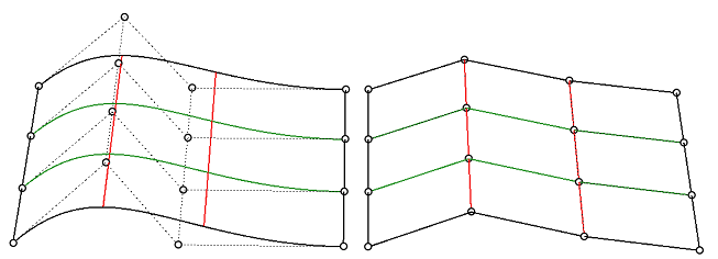
Two NURBS curves can be turned into a surface using Loft command. Notice that the control structure (the collection of control points) is very similar to the curves used to make the lofted surface. In the same manner, a NURBS curve can be edited by dragging control points. NURBS surfaces are modified when dragging control points.
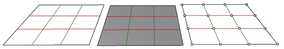
A few concepts associated with NURBS surfaces are useful to remember. NURBS surfaces are rectangular with two main directions: the “u” and “v” directions. The two directions do not have to be linear, so surfaces may bend in space. It is always useful to change the isocurves color going in the u-direction (e.g., set to red) from those going in the v-direction (e.g., set to green). It keeps you aware of the general structure of your surface. To do that, go to Rhino Options > View > Display Modes > [your mode] > Objects > Surfaces > Isocurve color usage
There is the idea of a “degree” in NURBS surfaces, and it defines the level of smoothness of the surface. With degree 1 surfaces, you end up with a faceted surface that has creases surrounding each unit area surrounded by adjacent control points. The higher the degree, the smoother the surface, but you typically need more control points to achieve it. Commonly used degrees are 1, 2, 3 and 5.
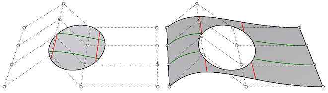
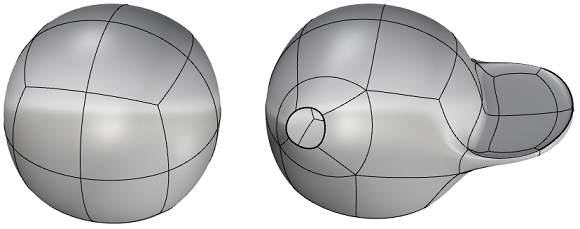
NURBS surfaces typically have a rectangular boundary. If the surface is non-rectangular, it will likely be “trimmed.” Trimming involves defining a boundary (using curves). The underlying surface remains rectangular, and you can always Untrim the boundary to go back to the original surface. Adding holes to a surface is the same as adding an irregular boundary. It involves trimming an inner boundary. Again, the underlying structure of the NURBS surface remains intact in all cases.
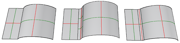
It is possible to Join surfaces together to make a bigger object. That happens if the two surfaces can be joined along at least one edge with the model tolerance. If you don’t plan carefully, the two surfaces might not connect smoothly. There are tools in Rhino to blend surfaces with the desired smoothness (or what is technically called continuity). One example is to use the BlendSrf command. It is also possible to blend or round the edges connecting two surfaces stitched together using a command such as FilletEdge and BlendEdge.
1.6.2 Solid geometry
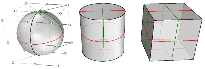
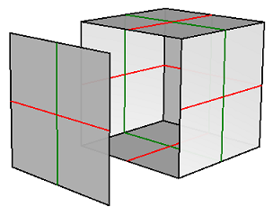
Rhino NURBS surfaces are infinitely thin; they have zero thickness. Enclosing a volume can be achieved with one or more surfaces stitched together as one object. The Solid menu includes all primitive forms such as Box, Sphere, Cylinder, etc.
The more common way to create a closed polysurface or solid in Rhino is to join enough single surfaces together to enclose a space producing a boundary representation, or brep for short. A box is an example of this type of object. We call these objects solids, but it is important to remember that nothing is inside them. They are volumes in space enclosed by infinitely thin surfaces. If you remove one side of a box and look inside, you will see the backsides of the five surfaces.
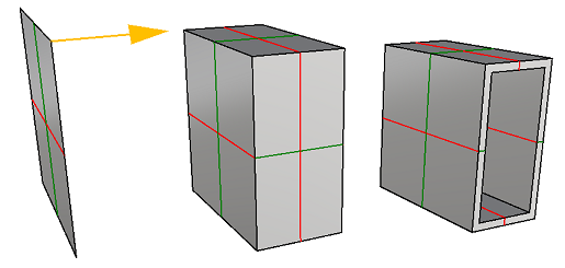
You can also create breps by extruding or offsetting surfaces. Shell command is another example of turning an open surface or polysurface into a solid with thickness.
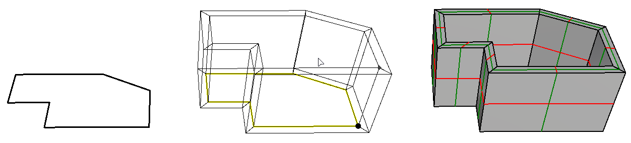
You can create solids from curves as input using commands such as Slab.
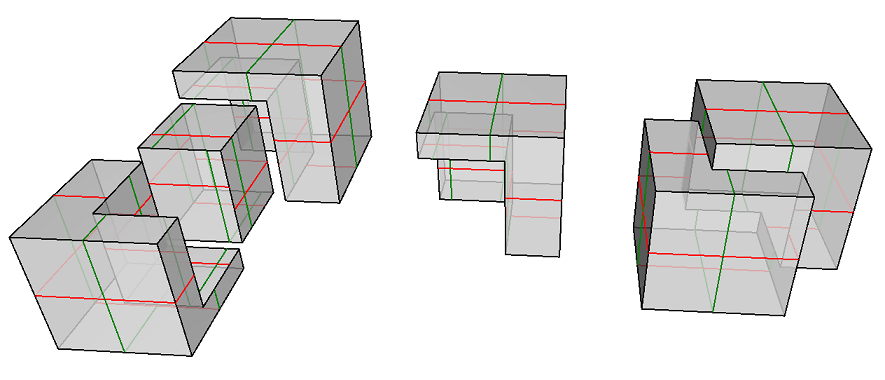
Some modeling operations work only with solids, most importantly, the Boolean Operations. Commands such as BooleanUnion, BooleanDifference, and BooleanSplit ensure that the results remain solid.
1.6.3 Extrusion geometry
Another object type that is related to a polysurface and a solid is the lightweight extrusion object. Lightweight extrusion objects use less memory, mesh faster, and save smaller than the traditional polysurfaces.
In models containing large numbers of extrusions represented by traditional polysurfaces, performance can be sluggish due to the relatively high demand on resources. If the same objects use a lightweight extrusion type, the model is more responsive and leaves plenty of memory available.
Rhino commands like Box, Cylinder, Pipe, and ExtrudeCrv create lightweight extrusion objects by default. They take up much less file size and can be very useful for dense architectural models with numerous rectilinear components such as structural elements. Note that editing these objects might result in converting them to Breps (typically when the operation result has no reasonable extrusion replacement).
1.6.4 Mesh geometry
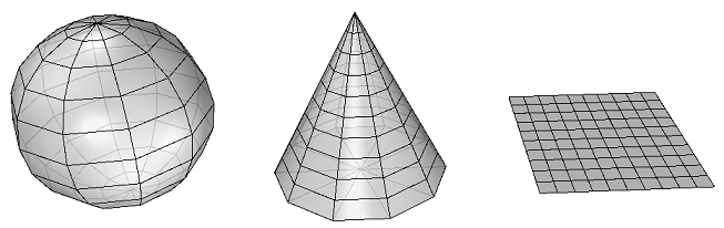
Rhino creates, edits, and otherwise uses polygon meshes. Polygon meshes are sometimes used to depict the same type of objects as surfaces, but there are important differences. Polygon meshes consist of a number, sometimes a very large number, of points in space connected by straight lines. These straight lines form closed loops of three or four sides, that is, polygons. The mesh geometry is described by 3D corner points (mesh vertices) creating faceted faces and straight edges. The mesh also describes the relationships between points to create edges and faces. Rhino supports mesh operations to edit meshes, boolean and repair.
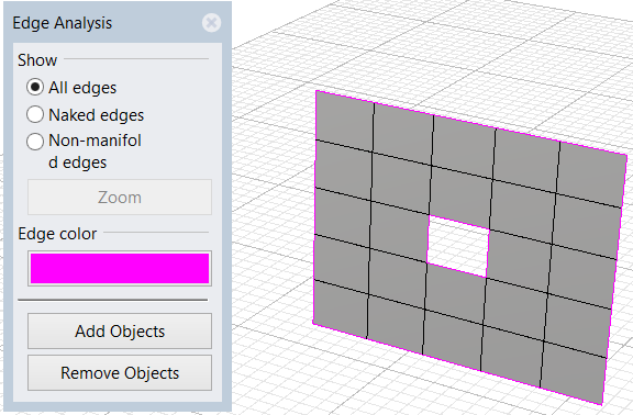
You can create mesh models in Rhino using triangular or quad mesh faces. Meshes can be open (boundary edges are called naked) or closed. Mesh edges can also be non-manifold (connect to more than two faces).
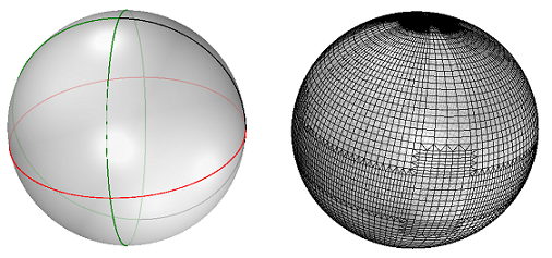
Meshes are used to create shading and renderings on the screen. If you display a NURBS surface in shaded mode, you are actually looking at the polygon mesh derived from that surface. All polysurfaces in Rhino have a render mesh attached to them to help create shading and rendering. The render mesh can be made more or less accurate based on speed and resolution requirements. Note that it is relatively easy to go from smooth breps to any resolution render mesh, but it is hard to turn a faceted mesh into a smooth brep. Meshes are also used for 3D printing. Deriving accurate meshes from surface models is important. Rhino has several tools to help accomplish this.
1.6.5 SubD geometry
 |
Introduction to SubD modeling... |
Rhino SubD objects are high-precision Catmull Clark subdivision surfaces. They can have creases, sharp or smooth corners, and holes. The Rhino SubD object is designed to quickly model and edit complex organic shapes. Unlike traditional mesh-based SubD implementations, Rhino SubD objects are NOT a subdivided mesh object. Rhino SubD surfaces are predictable, measurable, and manufacturable. They can be converted to either high-quality NURBS or mesh (quads or triangles) objects when needed. Rhino supports many commands to create SubD objects as primitive geometry or from curves using extrusions, lofting or sweep. It also supports a rich set of editing tools.
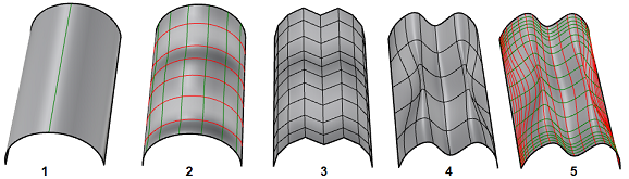
1.6.6 Transition between geometry types
Rhino supports converting between geometry types. For curves, a smooth NURBS curve can be turned into arcs or lines using the Convert command.
There are four main geometry types for surfaces: NURBS, extrusions, SubD, and meshes. There are a number of commands in Rhino to convert between surface types. In the image below, there are a few examples of transition between geometry types: (1) Extrusion, (2) To NURBS, (3) To Mesh, (4) To SubD, (5) To NURBS.
1.6.7 Geometry transformations
The common transformation commands include Move, Scale, Rotate, Project, and Mirror. These can be done in Rhino by running commands with these names. Some of them can be directly accessed using the Gumball control. Other more complex transformations include Twist, Stretch, Bend, and Flow. All transformation commands are accessible through the Transform menu.
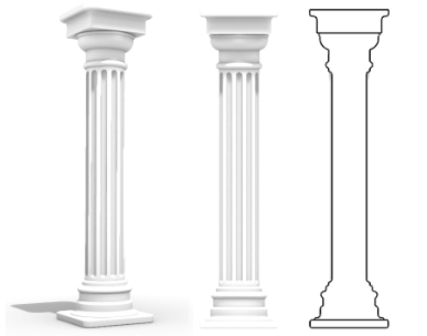
1.6.8 Geometry tutorial
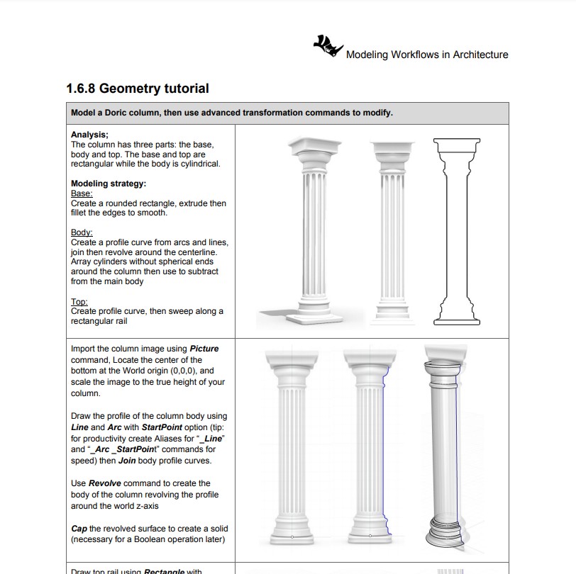 |
1.5.3 Tutorial handout... |
Model a Doric column and then use advanced transformation commands to modify it.
1.7 Units and tolerances
1.7.1 Overview
 |
Tolerances and Units... |
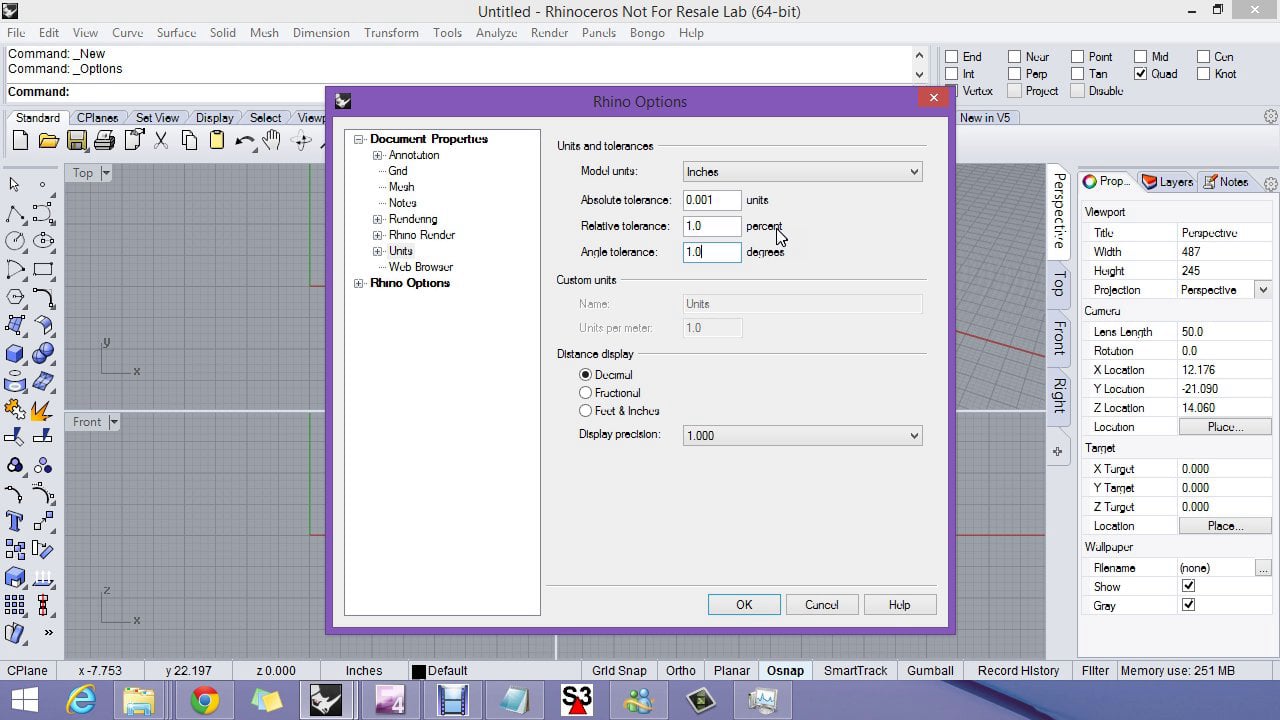
Rhino is always modeled in real full scale. So, if your building is measured in meters, you should use “Meters” as your units in Rhino. You can set your model units under Document Properties>Units. It is important that you check your units before starting any modeling. Units affect the scale of your model.
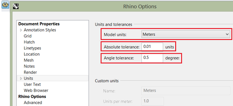
Rhino modeling involves two types of operations. One is exact, and the other is approximate. For example, when you create a circle, you specify the exact location in space for the center, and exact radius. Now, if you project this circle on a NURBS surface, it cannot be an exact operation in NURBS modeling. The amount of approximation is made within some tolerance. You can set that tolerance in the “Absolute tolerance” field. The smaller the tolerance, the tighter the model, but it may involve a more complex structure or take longer to calculate. You should consider what the model will be used for downstream when deciding what tolerance value to use. If the model is only used for visual representation or renderings, then tolerances can be relaxed. If you will pass the model to be printed or analyzed in some engineering application, you need to check acceptable tolerances in the target application. Angle tolerance is used to evaluate if two curves or two surfaces are tangent within that tolerance.
1.7.2 Attributes and data
Modeling objects consist of two parts: data and geometry. You can think of data as information that describes the geometry attributes such as name, color, material, linewidth, and group affiliation. Data also includes custom information specific to the modeler or the workflow.
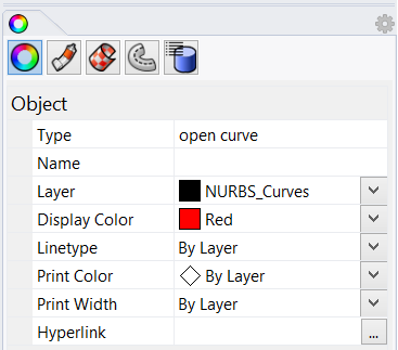
Rhino objects have attributes that can be accessed and set directly using the properties panel. Each geometry type has a different set of data and attributes associated with it, and they all appear as icons under the properties main tab.
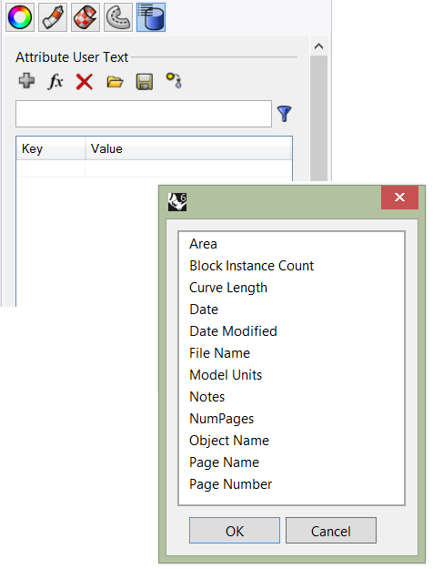
Users can attach custom data to objects using a user string. You can add functional attributes such as length or area, but you can also create your own key and value that is specific to your modeling workflows. For example, you may tag all your roof panels with the “Area” Key, and the area of each panel is calculated and attached. It also changes dynamically when the panels are scaled.
Rhino plugins can access objects’ user data and attach any information that can inform how particular objects display or behave.
Designers typically organize their model geometry and data in layers. This helps isolate and group data in one place. For example, you might put all your lights in one layer, site geometry in another and so on. Other than grouping data, layers allow you to hide, select all objects, or assign attributes. For example, you can assign color, lineweight or material to the layer instead of objects. There is extensive information about layers in the Rhino help file.
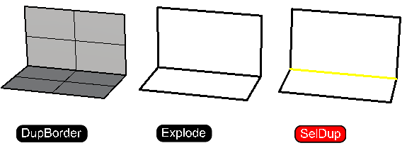
Selection tools by object type or attributes are other important tools to help navigate your model. For example, you might need to hide all points in the model. You can run SelPt, then Hide commands. You might also want to delete all duplicate geometry in a model. The command SelDup selects geometry that perfectly overlaps (within your document tolerance), then runs the Delete command. It is also possible to select objects with a certain name or color. Knowing how to use selection commands can improve your productivity.
There are also specialized tools to identify specific information about your model. For example, you might need to identify and zoom to a naked edge in a dense mesh using the ShowEdges command. This is important with mesh modeling to create clean closed mesh ready for 3D printing.
1.7.3 Attributes tutorial
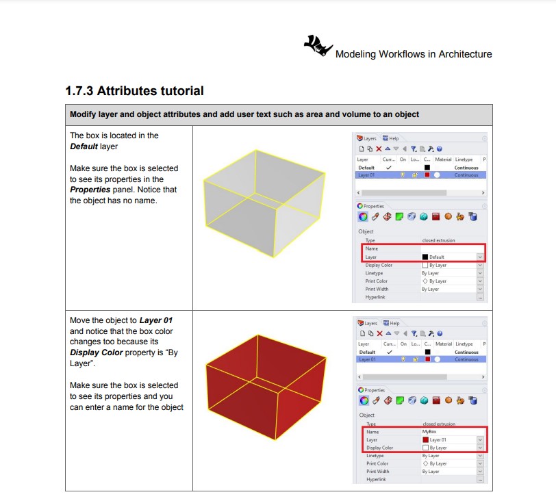 |
1.7.3 Tutorial handout... |
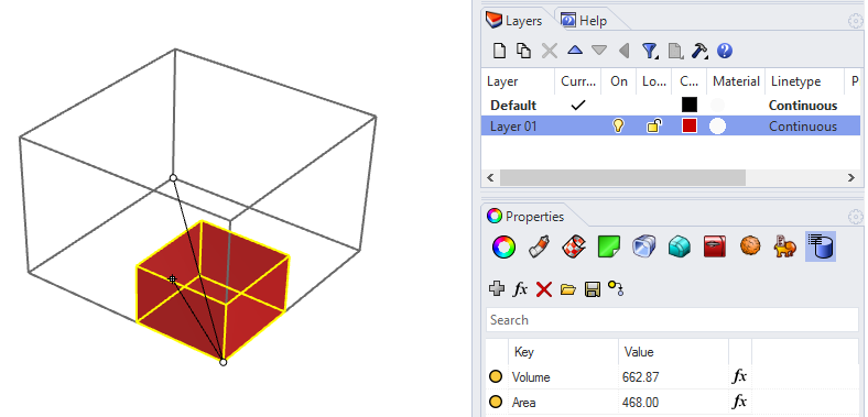
Modify layer and object attributes and add user text such as area or volume to an object.
1.8 Visualization
Communicating and presenting design work to others is integral to any creative workflow. Rhino includes a variety of options for visualizing and rendering. Display modes, interactive rendering, and a myriad of third-party plugins for rendering ensure you can capture and communicate your design intent as you create.
1.8.1 Display modes
 |
Introduction to display modes V6... |
 |
Custom display modes V6... |
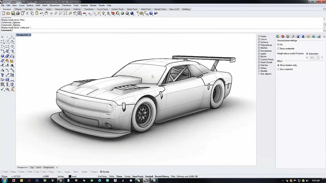
You can select display modes in the Rhino viewport via the viewport drop-down menus or by way of the Display panel at the right of the Rhino UI.
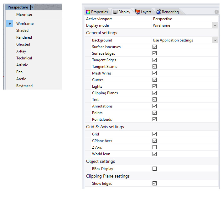
Display modes can also be created, customized, and saved through Rhino Options > View > Display Modes.

1.8.2 Rendering
 |
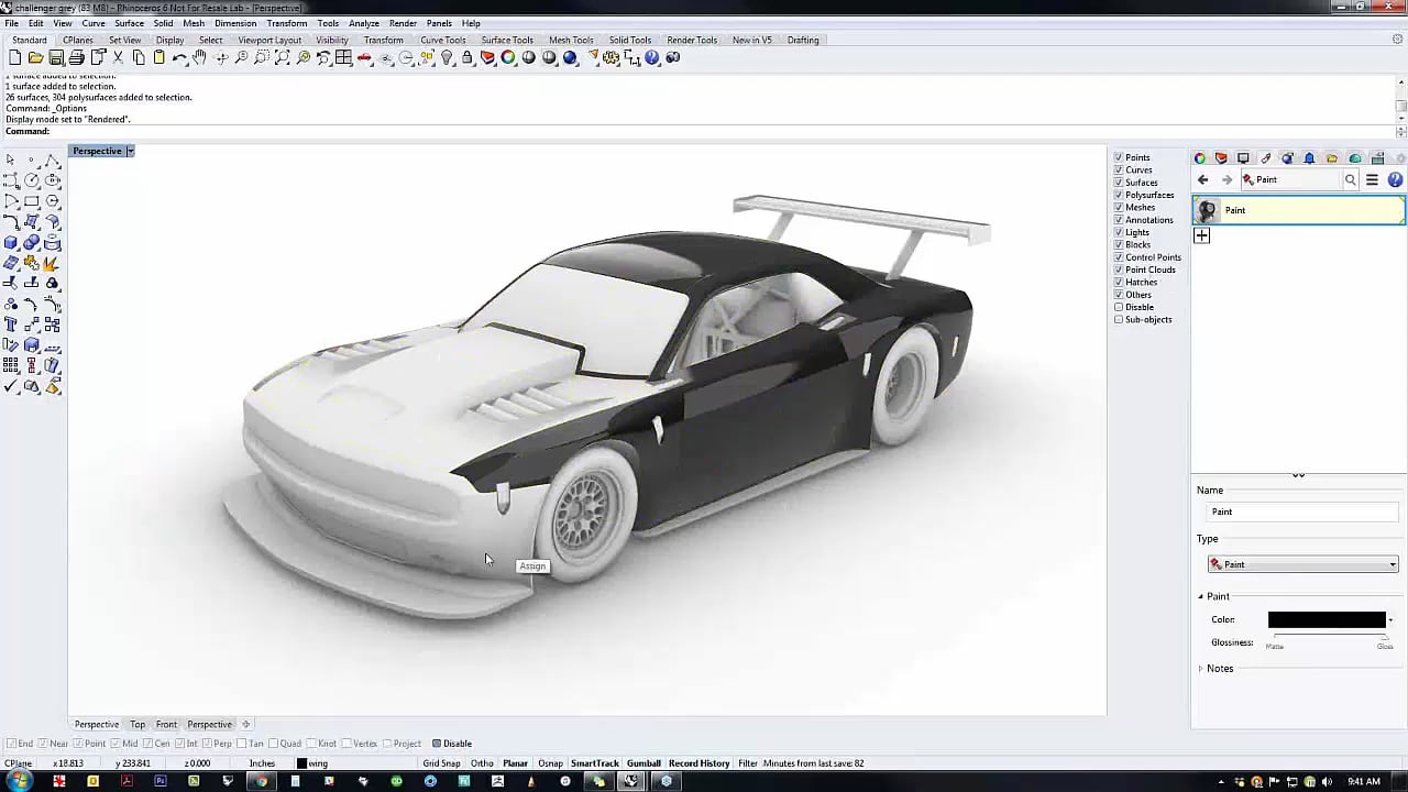
Introduction to materials V6... |
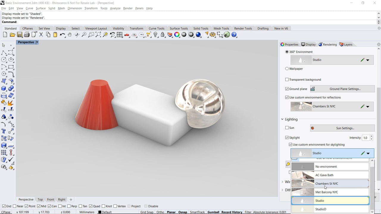 |
Introduction to rendering environments V6... |
 |
Getting started with realtime rendering V6... |
 |
Getting started with decals V6... |
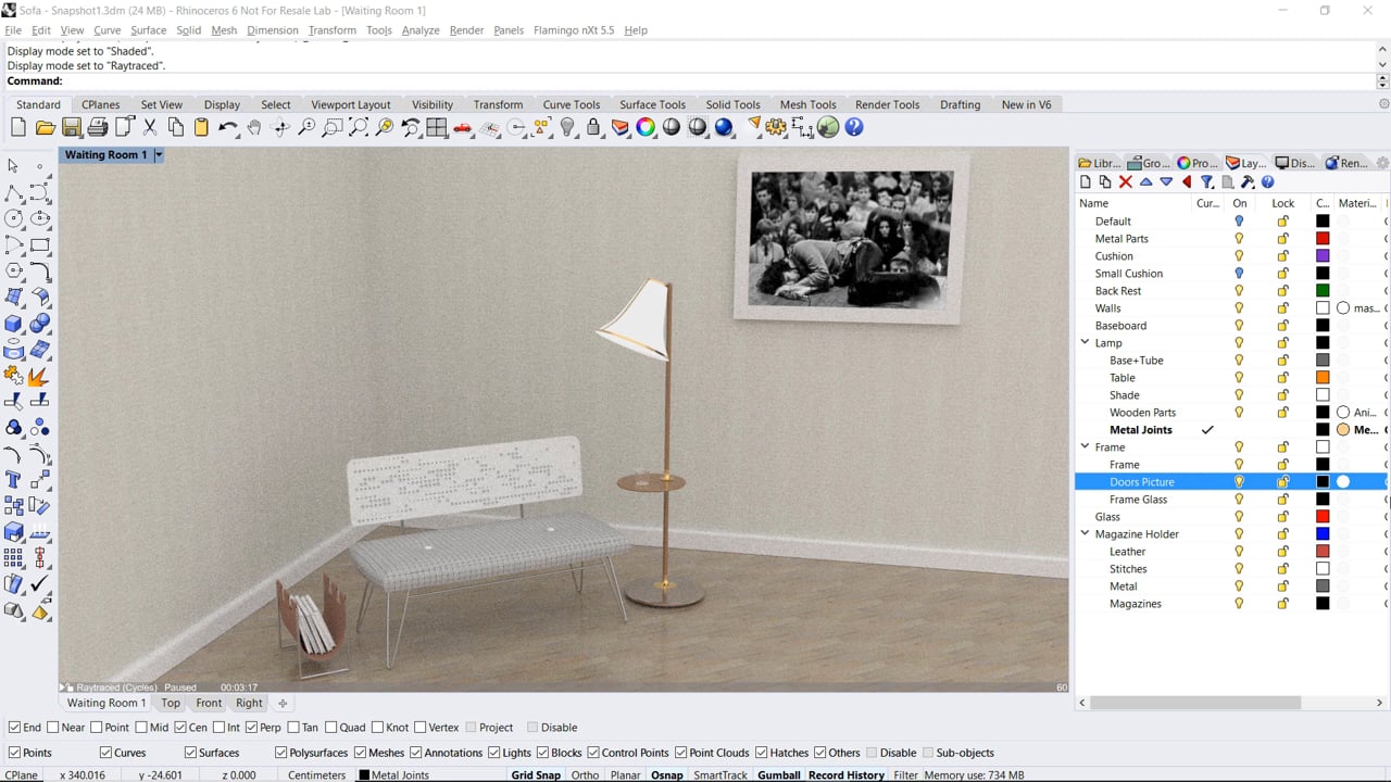
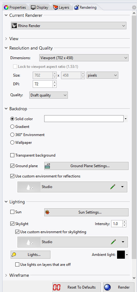
Rendering controls for the default Rhino Render, as well as the interactive rendering display mode called Raytraced, can be accessed in the Rendering panel. If you are using a separately installed rendering plugin in Rhino, refer to that plugin’s documentation for UI locations. The Render drop-down menu, then Current Renderer flyout, can be used to switch between rendering plugins.
1.9 2D drawing and annotation
Extracting 2D drawings from 3D models is common in most 3D modeling applications. In Rhino, there are few commands to help section through models, orient planar curves to any plane, and extract outlines of scenes. Section and Contour commands help extract one or a series of sections through a model. Sections remain in the true location of the 3D modeling space but can be moved or oriented to any plane using the Orient command. In essence, a section is the result of intersecting a plane with the model. Rhino has a robust Intersect command that can also be used to create sections.
Perspective or parallel views of a model can also be extracted as planar line drawing along with hidden line information and boundaries using the Make2D command in Rhino.
Section, Contour and Make2D create vector drawings consisting of curves and points that are actual geometry objects in Rhino. Those can be snapped to and annotated. If you simply need an image of your section or would like to look inside your model in the viewport, then you can use another set of commands. ClippingPlanes and ViewCapture are two very commonly used commands that are used for that purpose.
Rhino also supports a special paper space viewport called Layout. It supports placing views of the model to scale, add paper titles and Print to PDF and other formats.
1.10 Files
 |
Setting file templates... |
3D modeling applications save geometry and data to a file using a specific format. When a file format is publicly available (open source), other applications can easily add support to open files using that format. This helps promote interoperability among different applications and the flow of information. Rhino publishes its 3DM file format in OpenNURBS, allowing other applications to support it fully.
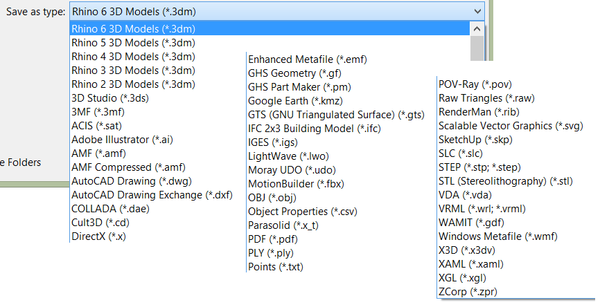
Some applications only support a limited number of geometry types or specialized object types. This makes interoperability more challenging, and some data is bound to be lost in the conversion. Rhino pays great attention to file I/O and supports many different import and export formats, making it possible to model in Rhino and then export your model to downstream processes, or import models from other software applications into Rhino. For a complete list of import and export file types, refer to the Rhino Help > Contents > File I/O > File Formats.
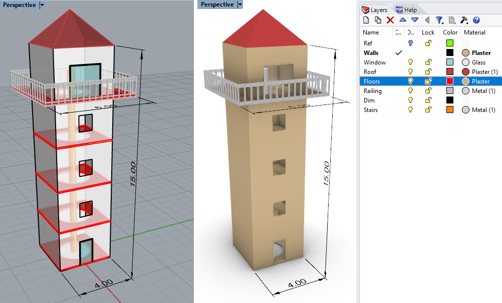
1.11 Lighthouse tutorial
 |
1.11 Tutorial handout... |
Model the following lighthouse using Rhino.