Create Solids from Curves
What is a Solid in Rhino?
In Rhino, a Solid is any Surface or Polysurface that is watertight and therefore encloses a volume. When all edges of a surface or group of surfaces are joined with no gaps, Rhino treates the object as a Solid.
Rhino can generate serveral types of solids like:
- Single-surface Solids
- Polysurfaces
- Extrusions
- Solid Meshes or (Mesh Solids)?
- Solid SubDs or (SubD Solids)?
Single-Surface Solids
A single
NURBS
surface can be designed so that it wraps around and joins itself into a closed form. Rhino creates these shapes usings commands such as
![]() Sphere
,
Sphere
,
![]() Torus
, and
Torus
, and
![]() Ellipsoid
. In order to edit this type of solids, you have to turn on their
Control Points
to manipulate the shape.
Ellipsoid
. In order to edit this type of solids, you have to turn on their
Control Points
to manipulate the shape.
PolySurfaces
A Polysurface is created combining several surfaces and are joined together into one closed volume. Primitive polysurfaces commands are:
These solids are composed of multiple surfaces, each contributing to the final closed form.
Extrusions
Extrusions are created when a curve or a surface is extended in a straight direction to generate a closed, volumetric form. They are one of the most efficient solid types because they maintain a lightweight mathematical structure and are easy to edit. Extrusions are generated using the Gumball Extrude Handles or using these Rhino commands:
Solid Modeling Fundamentals
In this guide, we will explore the fundamental tools and techniques for creating and editing solid geometry. You will learn how different types of solids are created and walk through essential editing commands such as
![]() Rebuild
,
Rebuild
,
![]() BooleanUnion
,
BooleanUnion
,
![]() FilletEdge
,
FilletEdge
,
![]() BlendEdge
and more to maintain a watertight model.
BlendEdge
and more to maintain a watertight model.
By the end of this guide, you will have a clear understanding of the solid-modeling workflow in Rhino and the best practices for producing a clean, reliable geometry for design, visualization, and fabrication.
Solid Creation
Before starting any project in Rhino, it is essential to set up your units to ensure accuracy throughout your work. For this tutorial, we will be using centimeters as our units of measurement.
As the project progresses, we will toggle layers on and off as needed and organize objects into appropriate layers to keep the geometry structured and the workflow clean and efficient.
To get started, click on the following link to download the Rhino file: Solids.3dm.
The project is divided into six parts:
- Rainbow Pipes.
- Wavy Box.
- Curvy Box.
- Cylindrical Post.
- Space Ball.
- Chameleon.
- Base
Lets get started!
Rainbow Pipes
For the first geometry, we will need to create some profile curves to create a solid using the pipe command.
Creating the Base Curve
- Maximize the viewport.
- On the
 Layer
panel, find the Rainbow layer and make the crvs
sub-layer current
.
Layer
panel, find the Rainbow layer and make the crvs
sub-layer current
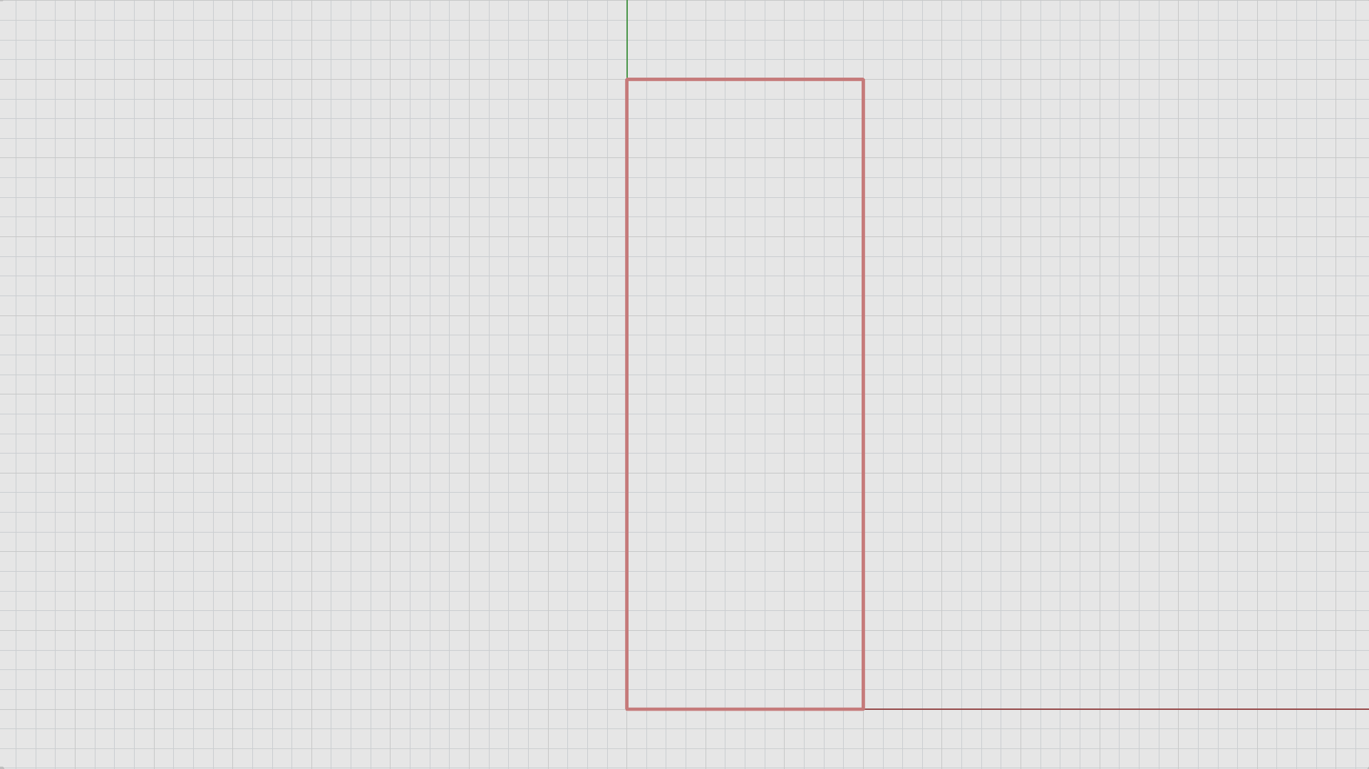
. - Run the
 Rectangle
command.
Rectangle
command. - For the First corner of rectangle, type 0. Press
.
Coordinate Entry TipTyping 0 for the first point will always snap the first point at the (0,0,0) coordinates.
- For Other corner or length, type 3. Press Enter.
- For Width, type 8. Press Enter.
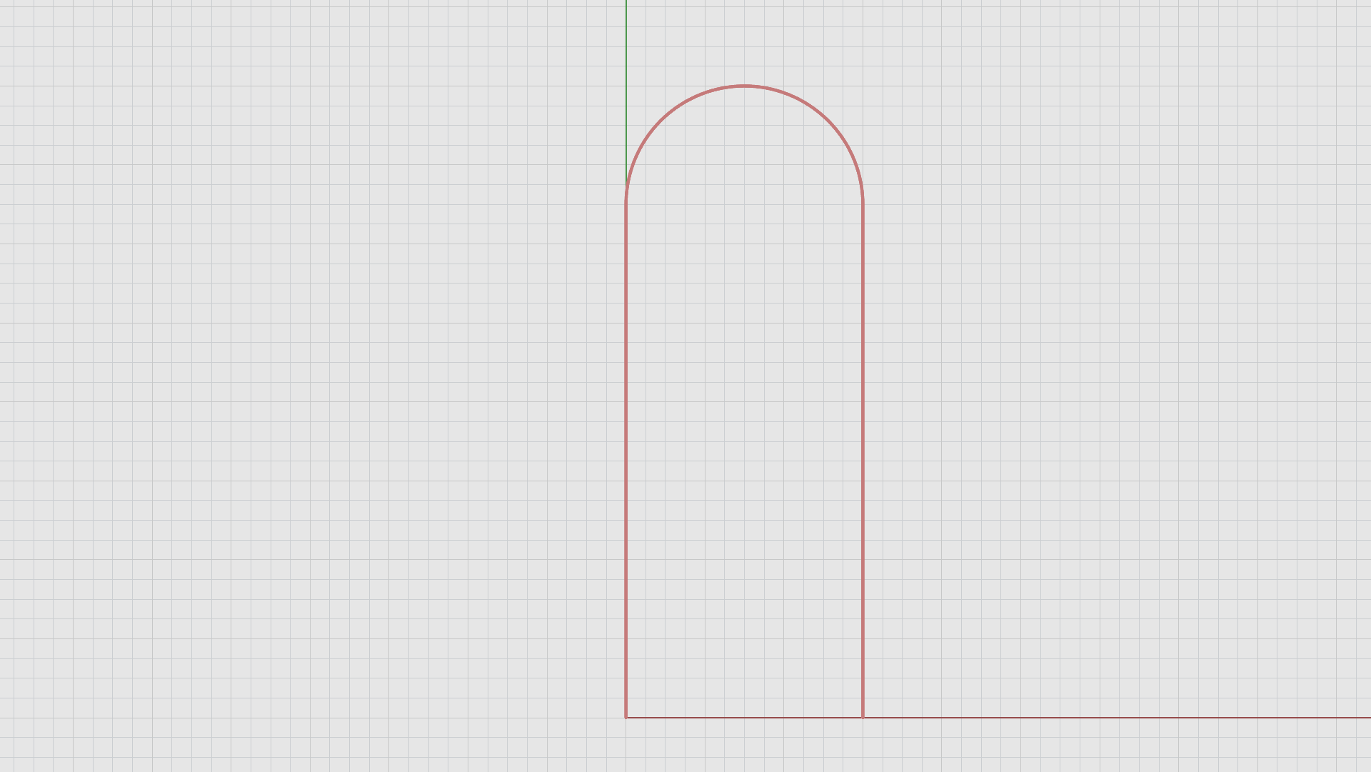
Rounding the Profile Curve Corners
- Run the
 Fillet
command.
Fillet
command. - On the
command prompt
make sure:
(Radius=1.5 Join=Yes Trim=Yes ExtendArcsBy=Arc ExtendOtherCurvesBy=Line Dynamic=No). - Type 1.5 for the radius. Press Enter.
- For First curve to fillet, select the right curve of the rectangle.
- For Second curve to fillet, select the top curve of the rectangle.
- Repeat the Fillet command on the left and top curves of the rectangle.
Now, we need to delete the bottom curve by using sub-object selection. Here’s how:
- Hold down the and buttons on your keyboard to Sub-object select the bottom curve of the rectangle and press the button.
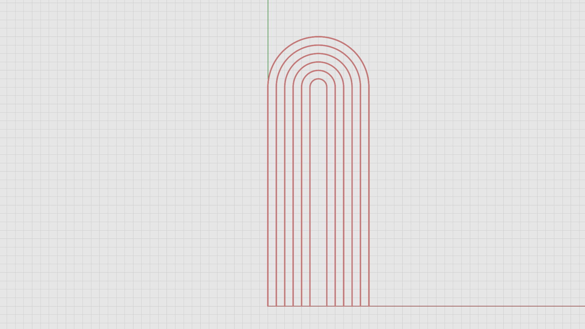
Create Copies of the Profile Curve at a Specified Distance Using the Offset Command
- Run the
 Offset
command.
Offset
command. - Type 0.25 for distance. Press Enter.
- For Select curve to offset, select the arch.
- Click inside the arch for direction.
- Repeat the offset command on each new curve untill you create 5 offsets which results in 6 curves in total.
The completed steps should produce the following results:
The following GIF demonstrates the full workflow: redo gif to show sub-obj sel with spot on mouse??
Create a Solid with the Pipe command
- Maximize the viewport.
- On the Layers panel, make the Rainbow: pipe sublayer current.
- Run the
 Pipe
command.
Pipe
command. - For Select rail, click on the second arch.
- On the
command prompt
, make sure:
(Output=Surface Thick=No Cap=Flat ShapeBlending=Local FitRail=No). - For Start radius, type 0.25. Press Enter.
- For End radius, type 0.25. Press Enter.
- Repeat the Pipe command for every other arch.
The following GIF demonstrates the full workflow:
Wavy Box
Creating the Base Curve
- Turn the Rainbow layer off .
- On the
Layer
panel, find the Wavy Box layer and make the crvs
sub-layer current
.
- Maximize the viewport.
- Run the
Rectangle
command.
- For the First corner of rectangle, type 0. Press .
- For Other corner or length, type -5. Press Enter.
- For Width, type 4. Press Enter.
To get the trapezoid shape. We will use the Gumball to move one control point on the top left corner of the rectangle. Here’s how:
- Select the rectangle and click on the top left control point of the rectangle.
- Click on the Gumball red move handle , type 2.
The following GIF demonstrates the full workflow:
Creating the Arcs
- Run the
 Explode
command.
Explode
command. - For Select objects to explode, select the trapezoid. Press Enter.
- Run the
 Divide
command.
Divide
command. - For Select curves to divide, select the tilted curve on the left side of the trapezoid.
- For Number of segments, type 7. Press Enter.
- Make sure the Point Osnap is enabled.
- Run the
 Polyline
command.
Polyline
command. - For Start of polyline, click on the first point at the top end of the curve.
- On the
command prompt
, click on:
(Mode = line)and change it to(Mode = Arc). - Again on the
command prompt
, click on
(Direction)and hold down , then click anywhere in the negative X-axis direction. - For Next point or polyline, select each point untill you reach the end of the line.
- Select the tilted curve. Press .
- Run the
 SelPt
command. Press Delete.
SelPt
command. Press Delete. - Run the
 Join
command.
Join
command. - For Select objects to join, select all the curves. Press Enter.
The following GIF demonstrates the full workflow:
Extrude
- Maximize the viewport.
- Make the Wavy Box: extrude sub-layer current.
- Select the shape and click on the Green Gumball Extrude Handle .
- Type 3. Press Enter.
The completed steps should produce the following results:
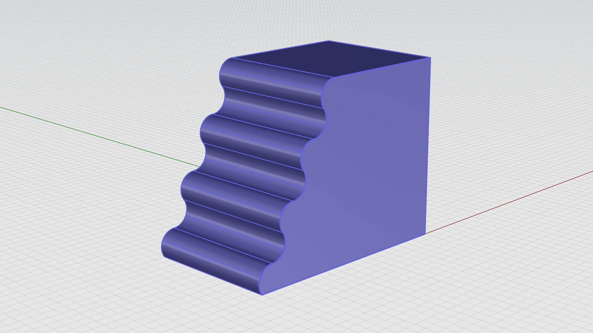
Fillet Edge
- Run the
 FilletEdge
command.
FilletEdge
command. - For Select edges to fillet, type 1.
- Select the top right edge of the extrusion. Press Enter.
- Press Enter again to end the command.
- Run the FilletEdge command again, type 0.1.
- Double click on the top edge to chain the edges.
- Do the same to the edges on the left side of the extusion. Press Enter.
- Press Enter again to end the command.
The following GIF demonstrates the full workflow:
Curvy Box
The Box
- Maximize the viewport.
- Turn the Wavy Box layer off.
- On the
Layer
panel, find the Curvy Box layer and make the box
sub-layer current
.
- Run the
 Box
command.
Box
command. - For First corner of base, type 0,-3.5.
- For Other corner of base or length, type 4,-0.25.
- For Height, type 3. Press .
The Circles
- Maximize the viewport.
- Run the
 Circle
command.
Circle
command. - Make sure the End snap is enabled.
- For Center of circle, select the bottom right corner of the box.
- For Radius, type 2.5. Press Enter.
Let’s create another circle with two-points:
- Make sure the End and Int Osnaps are enabled.
- Run the Circle command again.
- On the
command prompt
, select
(2Point). - For Start of diameter, select the top right corner of the box.
- For End of diameter, select the point where both circles intersects.
The following GIF demonstrates the full workflow:
Gumball Cut and Boss
- Maximize the viewport.
- Make sure the Gumball is enabled.
- Select the large circle, then drag the green cut handle on the Gumball to cut straight through the box.
- To Boss: Select the smaller circle, hold down the key on your keyboard.
- Click on the Gumball greed cut handle, type 3.25. Press .
- Run the
 SelCrv
command to select the curves in the scene. Press
.
SelCrv
command to select the curves in the scene. Press
.
The following GIF demonstrates the full workflow:
Fillet Edges
- Run the
FilletEdge
command.
- For Select edges to fillet, type 1.
- Select the straight edge on the top left of the extrusion. Press Enter.
- Press Enter again to end the command.
- Run the FilletEdge command again.
- For Select edges to fillet, type 0.5.
- Select the bottom two edges on the left and right side of the extrusion. Press Enter.
- Press Enter again to end the command.
Fillet Face Edges
- Run the FilletEdge command one more time.
- Type 0.1. Press Enter.
- On the command prompt, select
(FaceEdges). - Select the front and back faces of the extrusion. Press Enter.
- Press Enter again to end the command.
The fillet workflow is demonstrated in the GIF below:

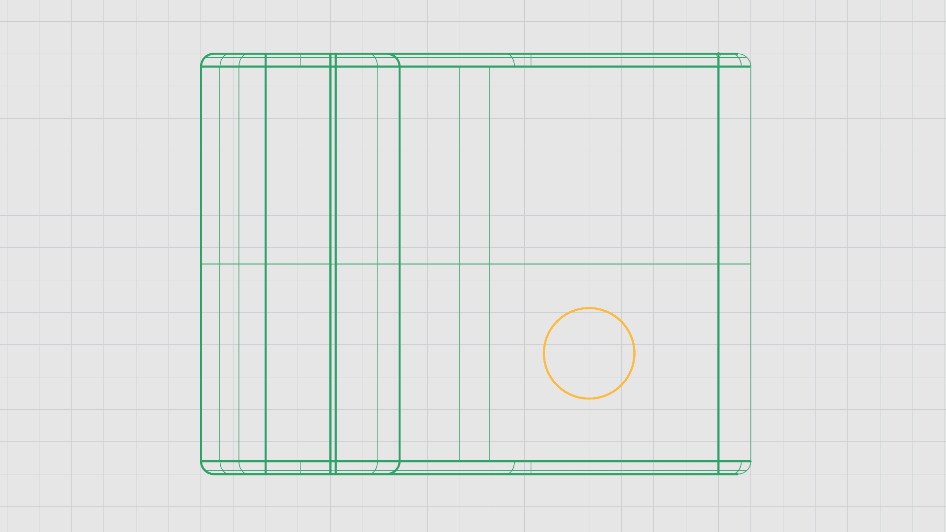
The Cylindrical Post
- Maximize the viewport.
- Change the Display Mode to Wireframe.
- Make the Curvy Box: cylinder sub-layer current.
- Run the
 Cylinder
command.
Cylinder
command. - For Base of cylinder, find a place on the top cplane for the base point.
- For Radius, type 3.5.
- For End of cylinder, type 0.5.
The Top view in wireframe should look as follows:
In the next stage of this process, we will complete the cylinder post by using sub-object selection by holding down the Shift and/or Ctrl keys on your keyboard along with the Gumball Extrude Handles. That way we can control the direction and scale of the extrusion, allowing us to manupilate the shape and acheive the desired outcome and propotion.
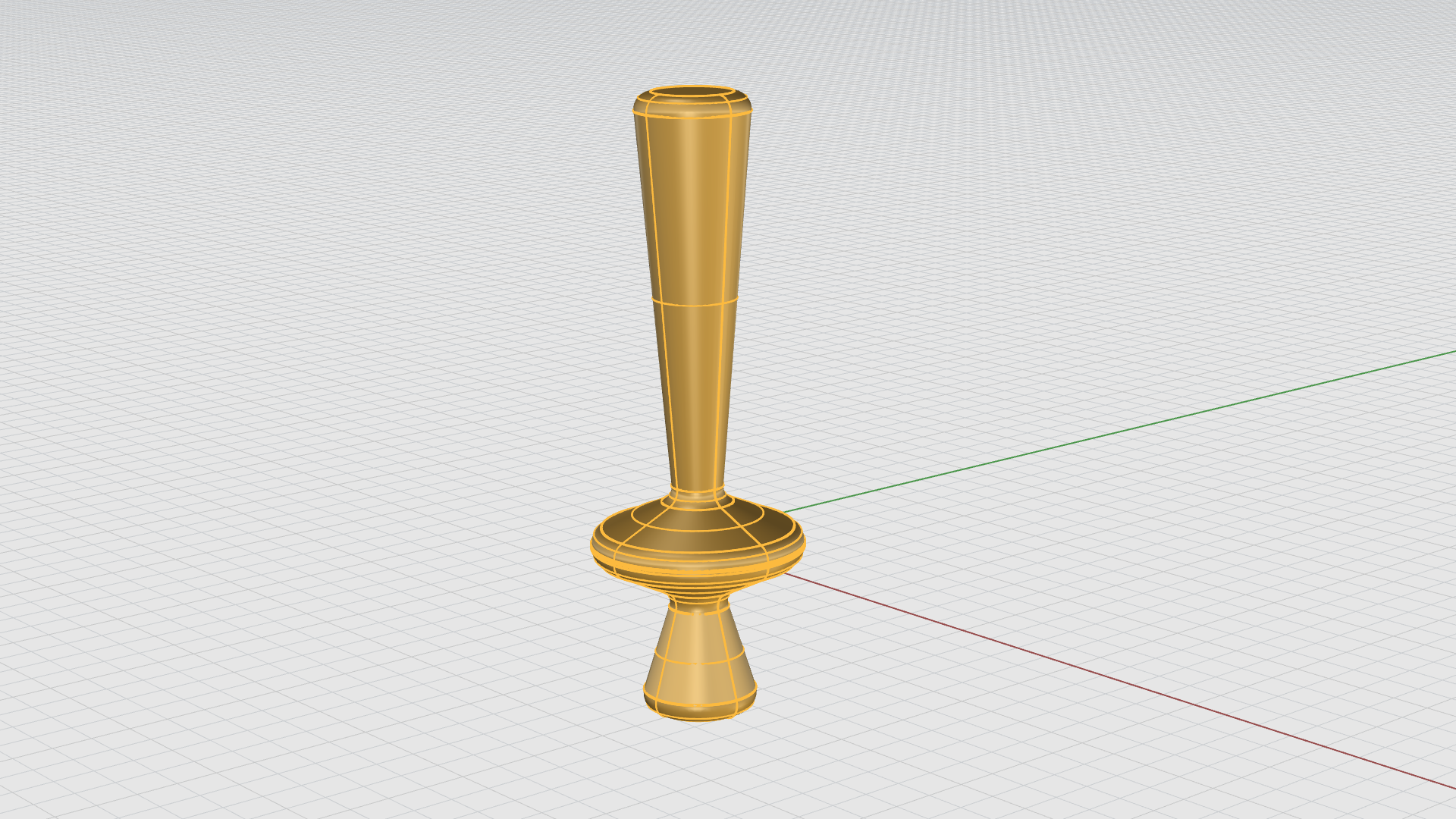
Creating the Post
- Maximize the viewport.
- Change the Display Mode back to Shaded.
- Hold down the and keys on your keyboard to activate sub-object selection .
- Select the top face of the cylinder.
- Click on the Gumball Blue Extrude Handle.
- Type 0.25. Press .
- Repeat the same process twice on the new faces.
- Now select the top face of the last extrusion but this time type 2.5. Press Enter.
The following GIF demonstrates the full workflow:

The result is a closed solid polysurface with 7 surfaces:
Manupilating the Post with the Gumball
- Hold down the Shift and Ctrl keys on your keyboard and select the third surface from the bottom.
- Hold down the Shift key and drag the Red scale handle on the Gumball to scale the surface outwards uniformly.
- Drag the Green scale handle to scale the surface in one direction.
- Using the sub-object selection method: Select the bottom edge of that same surface to scale it uniformally.
- Do the same for the top edge.
- Drag a crossing window from left to right to select objects entirely inside the window and highlight the diamond result.
- Move it using the Gumball move arrow in the Z direction.
- Keep manipulating the edges and faces untill you end up with the desired shape.
The following GIF demonstrates the full workflow:
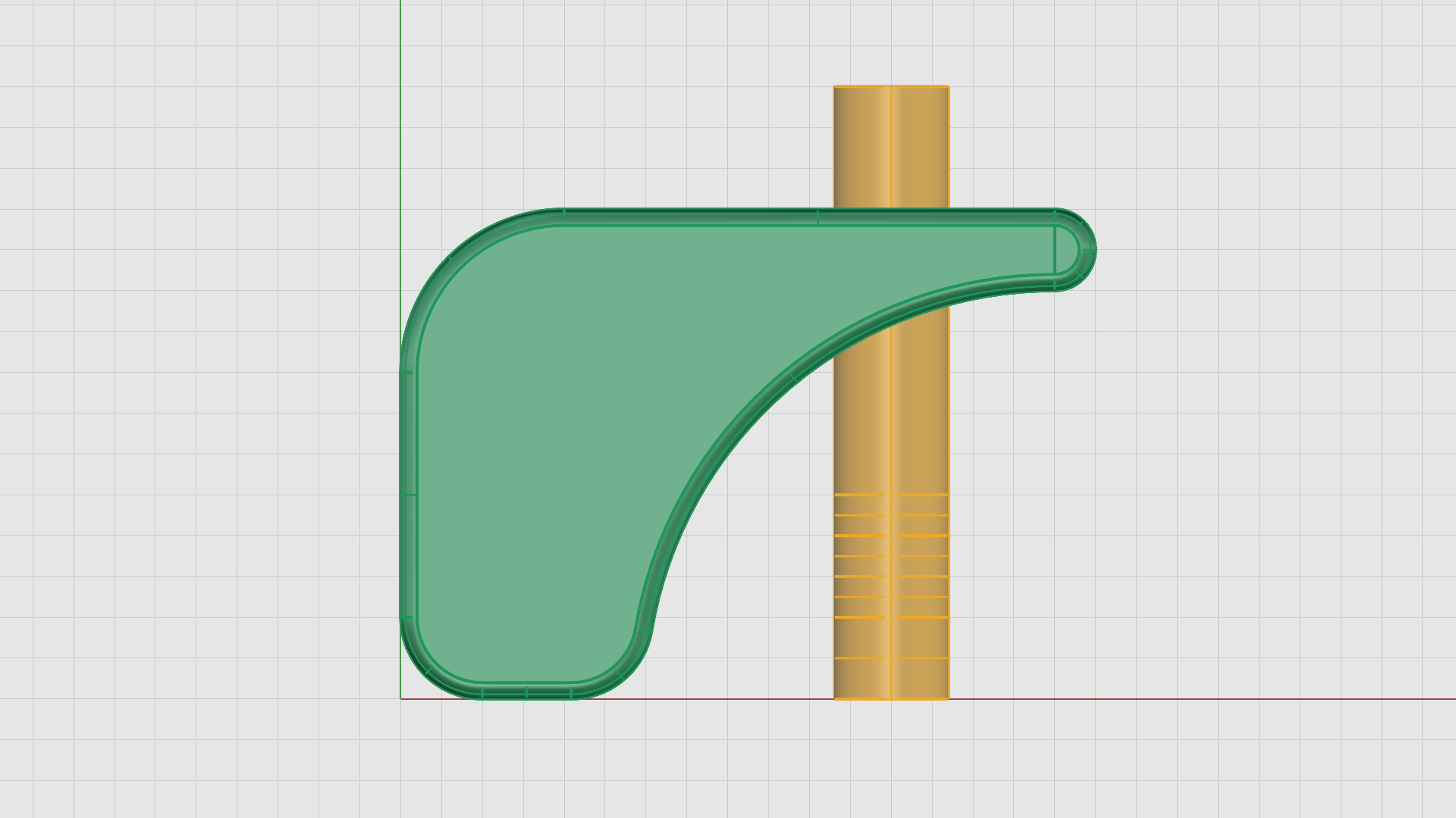
Fillet
- Maximize the viewport.
- Hide the Box layer.
- Run the
FilletEdge
Command.
- For Select edges to fillet, type 0.1. Press Enter.
- On the command prompt, select
(FaceEdges). - For Select polysurface faces for filleting all adjoining edges, drag a crossing window to select all edges of the post.
- Press Enter when done.
- Press Enter again to end the command.
You should now see a result similar to the following:
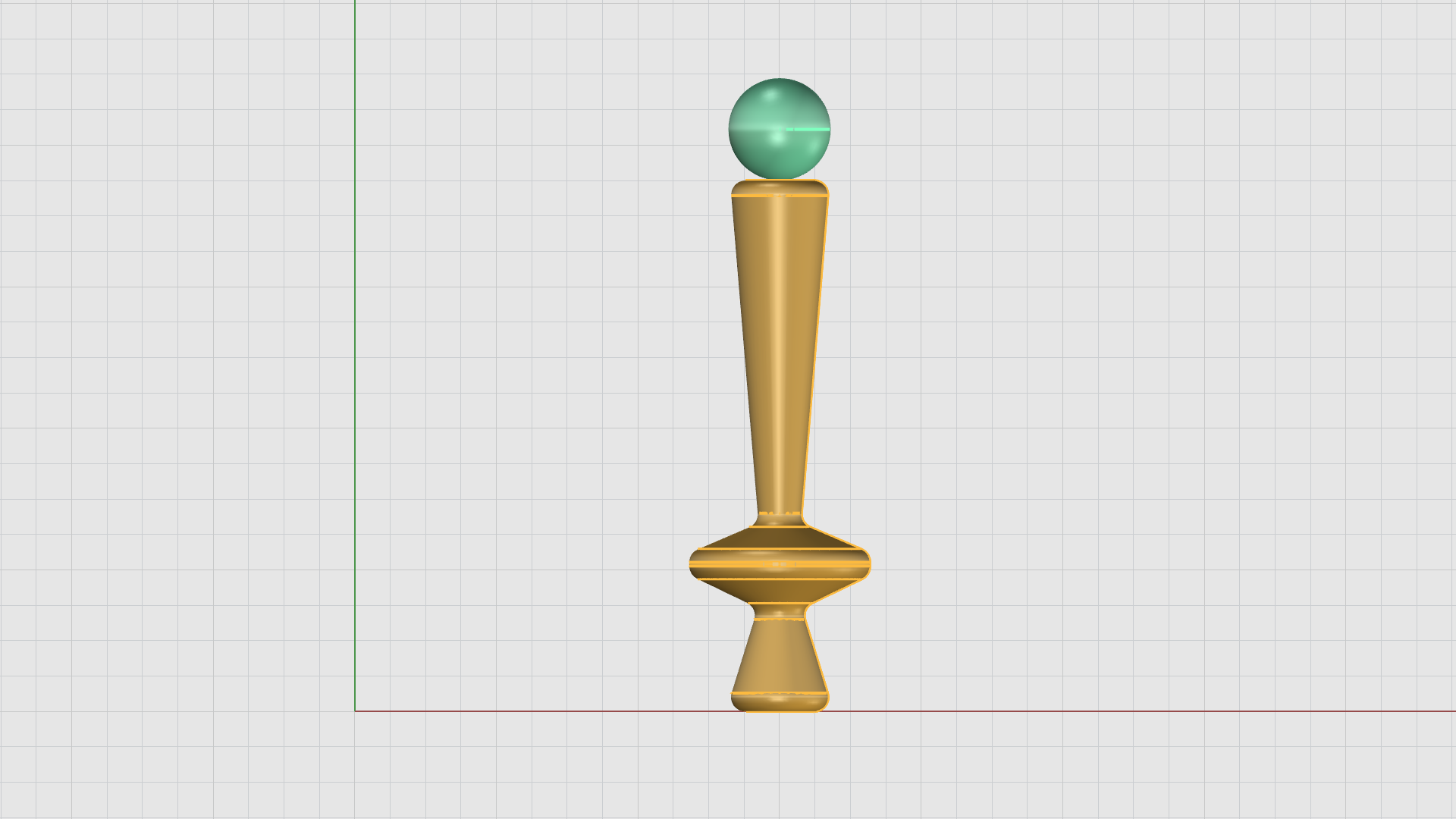
The Sphere
- Maximize the Front Viewport.
- On the
Layer
panel, make the Cylinder Post: sphere
sub-layer current
.
- Make sure the Cen Osnap is enabled.
- Run the
 Sphere
command.
Sphere
command. - On the command prompt, select
(2Point). - For Start of diameter, hover over the top surface of the cylinderical post to snap to its center.
- For End of diameter, type 0.7.
- Hold down shift to activate ortho.
- Click to end the command.
You should now see a result similar to the following:
Space-Ball
In this excersice, we will model a space-ball. We will begin by creating a basic sphere, then apply the Rebuild command to give it more structure. Next we will extract the iso-curves using the ExtractWireframe command and use their intersection points as guides to place smaller spheres. Finally, we will combine all the spheres using the BooleanUnion command to produce a single, closed polysurface.
- Turn the Wavy box and Curvy Box layers On.
- Maximize the viewport.
- On the
Layer
panel, find the Space Ball layer and make the ball
sub-layer current
.
- Run the
Sphere
command.
- For Center of sphere, find a place between the boxes.
- For Radius, type 1.25.
- Maximize the viewport.
- Use the Gumball Move Handles to position the sphere on the construction plane.
- Turn the Wavy box and Curvy Box layers off.
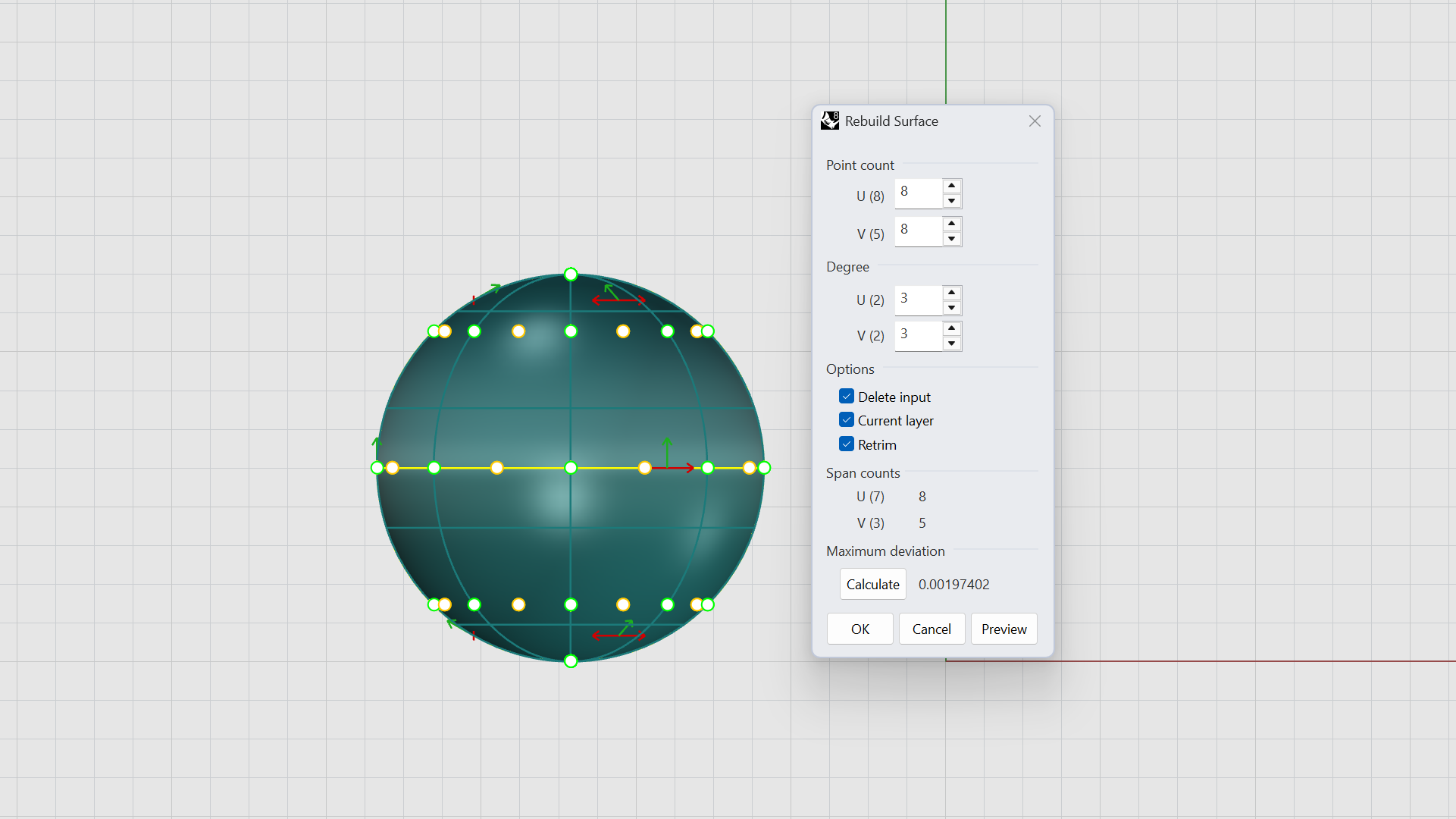
Rebuild and Wireframe
- Make the wireframe sub-layer current .
- Run the
 Rebuild
command.
Rebuild
command. - For Select curves, extrusions or surfaces to rebuild, select the sphere.
- The Rebuild surface settings window will appear.
- Change the Point count and Degree to the following:
Point Count: U=8, V=8.
Degree: U=3, V=3.
Delete Input: Checked.
Current Layer: Checked.
ReTrim: Checked. - Click Ok.
- Run the
 ExtractWireframe
command.
ExtractWireframe
command. - For Select surfaces, solids, meshes or SubDs to convert to curves, select the sphere. Press Enter.
- Turn the ball sub-layer off .
- Make sure the Int Osnap is enabled.
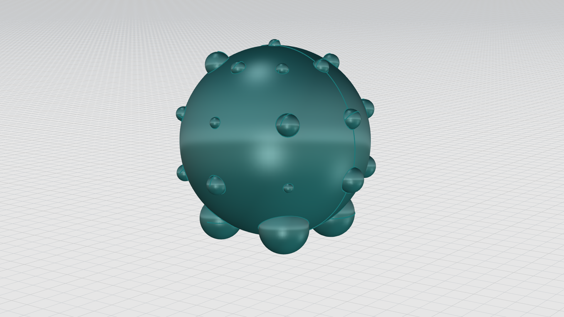
- Run the
Sphere
command.
- For Center of sphere, click on the wireframe intersection and create a small sphere.
- Repeat the Sphere command and create spheres with different radii at the intersections of the wireframe.
The following GIF demonstrates the full workflow:
- Turn the ball layer on .
- Make the ball layer current .
- Run the
 BooleanUnion
command.
BooleanUnion
command. - On the command prompt, make sure:
(DeleteInput=**Yes** and MergeCoplanarFaces=**Yes). - For Select surfaces or polysurfaces to union, select all the spheres in the scene by dragging a crossing window. Press Enter.
The BooleanUnion command creates a closed polysurface.
You should now see a result similar to the following:
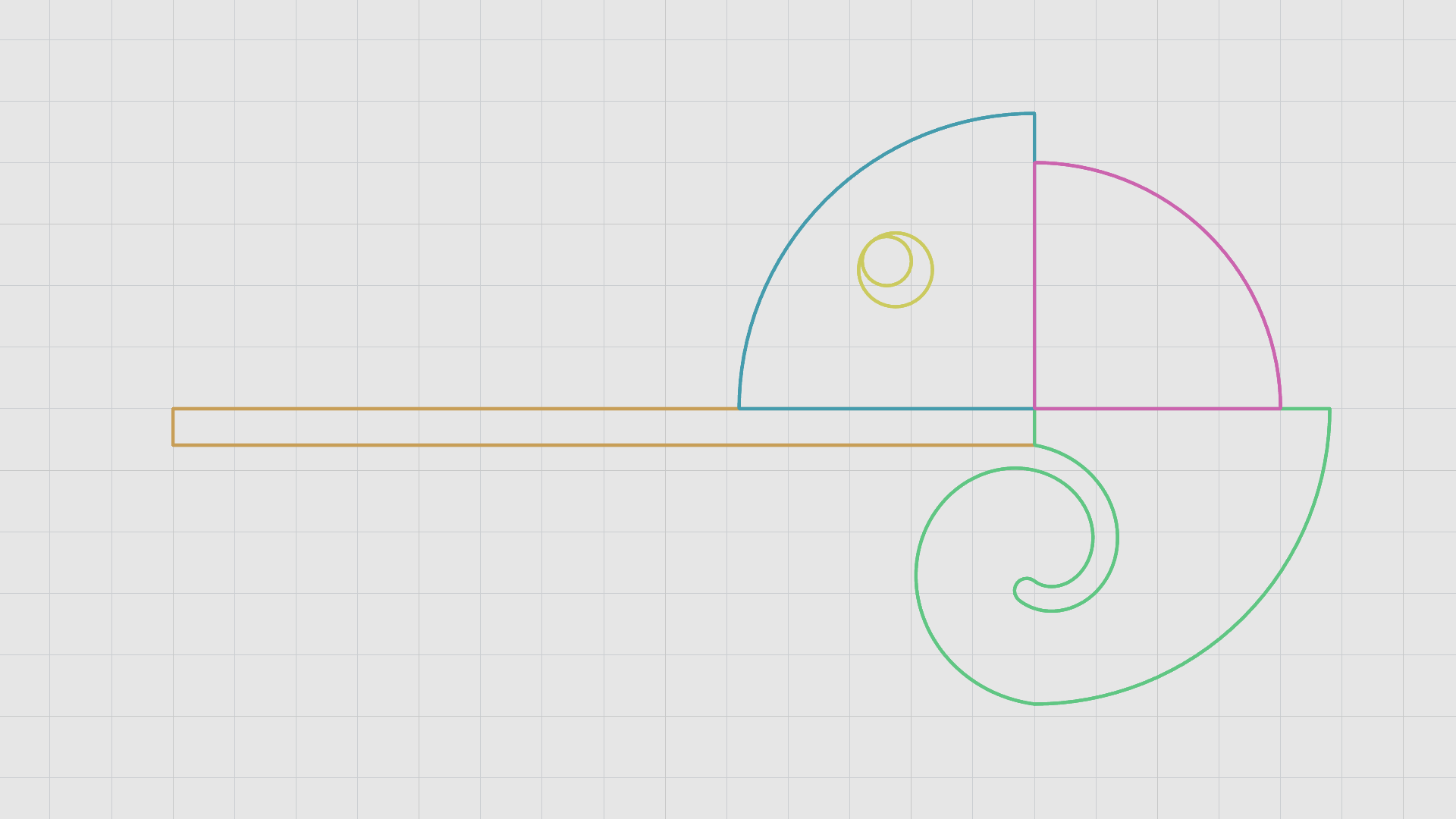
The Chameleon
In this part of the exercise, we will create an abstract chameleon by building its form from simple shapes such as polylines, circles, and spirals. These curves will be refined using basic curve-editing tools like , Offset, Trim and CurveBooleon. Once the curves are closed, they will be extruded to form closed polysurfaces. Finally, we will apply solid modeling tools, such as FilletEdge and BlendEdge, to soften and refine the edges, resulting in a smooth and cohesive 3D form.
Creating the Chameleon Outline: The Circles
- Maximize the viewport.
- On the
Layer
panel, find the Chameleon layer and make the crvs
sub-layer current
.
- Run the
circle
command.
- For center of circle, type these X and Y corrdinates: 3,11. Press Enter.
- For Radius, type 1.2. Press Enter.
- Run the
Offset
command.
- Type 0.2 for distance.
- For Select curve to offset, select the circle.
- For Side to offset, select inside the circle for direction.
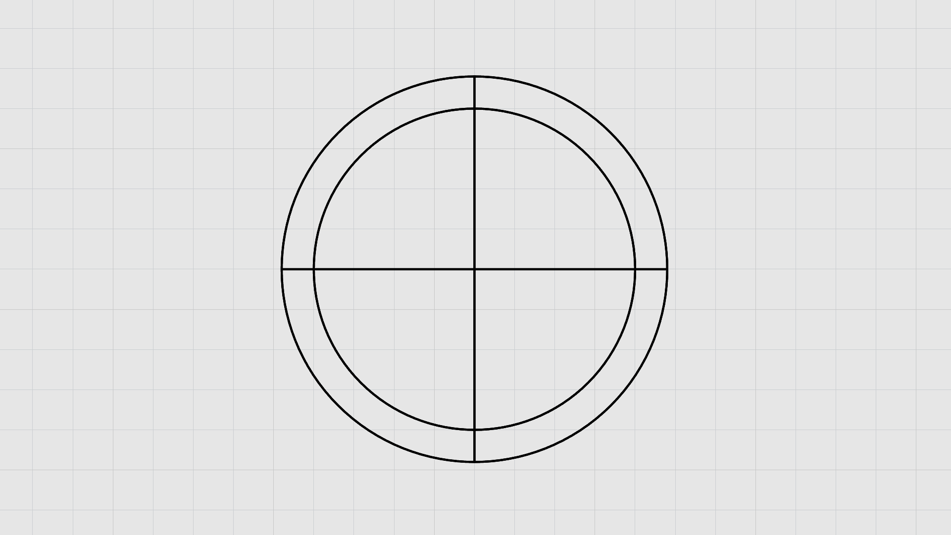
Creating the Chameleon Outline: The Lines
- Run the
Polyline
command.
- Make sure the Quad Osnap is enabled.
- For Start of polyline, select a point at the top quad of the first circle.
- For Next point of polyline, select the opposite point at the bottom quad of the first circle.
- Repeat the same steps to draw another polyline from the remaining quads so it crosses the first line.
You should now have two intersecting lines forming a (+) shape like the image below:
Creating the Chameleon Outline: Trim
- Run the
 Trim
command.
Trim
command. - Drag your cursor from left to right to window select the circles and lines. Press Enter.
- Click on the unwanted curves to trim them away as illustrated in the GIF below:
The following GIF demonstrates the full workflow:
Creating the Chameleon Body Parts: Curve Boolean
- Run the
 CurveBoolean
command.
CurveBoolean
command. - On the
command prompt
, make sure:
(DeleteInput=All CombineRegions=No Output=Curves SimplifyCurves=Yes). - For Select curves, select all the trimmed curves.
- For Click inside regions to keep, pick a point inside the shapes to create the closed curves. Press Enter.
The following GIF demonstrates the full workflow:
Creating the Chameleon Tail (Part 1): Spiral
- Make sure the Mid and End Osnaps are enabled.
- Run the
 Spiral
command. Press Enter.
Spiral
command. Press Enter. - On the command prompt: Select
(Flat). - For Spiral center, select the mid-point of the straight edge of third quadrant.
- For First radius and start point, type 0.1. Press Enter.
- Press Enter again.
- On the command prompt, make sure:
(Turns=1). - For Second radius, select the End point at the bottom of the quadrant.
The following GIF demonstrates the full workflow:

Creating the Chameleon Tail (Part 2): Offset
- Run the
Offset
command.
- For Select curve to offset, select the spiral curve.
- On the command prompt: make sure:
(Cap=Round). - For Distance, type 0.1.
- For Side to offset, click on the outter side of the curve to end the command.
The following GIF demonstrates the full workflow:
Creating the Chameleon Tail (Part 3): Curve Boolean
- Run the
CurveBoolean
command again.
- On the command prompt, make sure:
(DeleteInput=All CombineRegions=Yes Output=Curves SimplifyCurves=Yes). - Select the bottom quadrant and the spiral curve.
- For Click inside regions to keep, click inside the third quadrant along with the tail outline to create a closed curve. Press Enter.
The following GIF demonstrates the full workflow:
Creating the Chameleon Eyes: The Curves
- Make sure End and Mid Osnaps are enabled.
- Run the
Polyline
command.
- For Start of polyline, select the End Point at the center of the first quadrant.
- For Next point of polyline, snap to the midpoint of the arc on the chameleon head. Press Enter.
- Make sure Int and Near Osnaps are enabled.
- Run the
Circle
command.
- For Center of circle, find a place on the line but away from the edge for the center point.
- For Radius, type 0.15. Press Enter.
- Run the Circle command again.
- On the command prompt, select
(Tangent). - For First Tangent, hover over the circle and snap onto the intersection of the circle and line.
- For Second tangent type 0.1. Press Enter.
- Click on the line to end the command.
- Select the polyline. Press Delete.
The following GIF demonstrates the full workflow:
Creating the Chameleon Tongue: The Curves
- Run the
Rectangle
command.
- On the command prompt, select
(3Point). - For Start of edge, click on the end point where all quads meet.
- For End of edge, click on the opposite end point.
- For Width, type 3.5. Press Enter.
The following GIF demonstrates the full workflow:
Now that all the curves are closed and ready for extrusion, we will organize them into seperate layers to make modeling easier and effecient.
- Select each part of the chameleon.
- From the
Layer
panel, right-click on the layer name and click on
Change Object Layer
.
You should now see a result similar to the following:
Chameleon Solid: Extrude
The Head
- Maximize the viewport.
- Make sure the Gumball is enabled.
- Make sure the Chameleon: Head sub-layer is current.
- Hold down the Shift key to select the cameleon head with the larger circle for the eyes.
- Hold down the Shift key again and click on the Green Gumball Extrude Handle to extrude the curve in both directions. Type 0.25.
The Back
- Make sure the Chameleon: Back sub-layer is current.
- Select the chameleon back curve.
- Click on the Green Gumball Extrude Handle, type 0.25.
The Tail
- Make sure the Chameleon: Tail sub-layer is current.
- Select the chameleon tail curve.
- Hold down the Shift key again and click on the Green Gumball Extrude Handle to extrude the curve in both directions. Type 0.25.
The Eyes
- Make sure the Chameleon: Eyes sub-layer is current.
- Select the smaller circle for the eyes.
- Hold down the Shift key again and click on the Green Gumball Extrude Handle to extrude the curve in both directions. Type 0.125.
The Tongue
- Make sure the Chameleon: Tongue sub-layer is current.
- Select the rectangle curve.
- Hold down the Shift key again and click on the Green Gumball Extrude Handle to extrude the curve in both directions. Type 0.15.
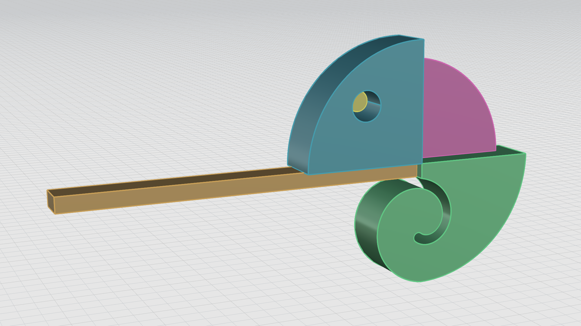
You should now see a result similar to the following:
Chameleon Blend Edges
- Turn the Chameleon: Eyes, Back, Tail, and Tongue sub-layers off .
- Change the Display Mode to Ghosted.
- Run the
 BlendEdge
command.
BlendEdge
command. - For Select edges to blend, type 0.2. Press Enter.
- Drag your cursor from left to right to select all the edges of the chameleon head.
- Hold the Ctrl key to de-select the circles for the eyes. Press Enter.
- Press Enter again to end the command.
- Run the BlendEdge command again.
- For Select edges to blend, type 0.07. Press Enter.
- Select the circle edges for the eyes. Press Enter.
- Press Enter again to end the command.
- Change the Display mode back to Shaded.
The following GIF demonstrates the full workflow:
- Turn the Chameleon: Head sub-layer Off.
- Turn the Chameleon: Eyes, Back, Tail and Tongue layers On.
- Run the
FilletEdge
command.
- For Select edges to fillet, type 0.07. Press Enter.
- Drag your cursor from left to right to select all the edges of the visible parts of the chameleon. Press Enter.
- Press Enter again to end the command.
- Turn the Chameleon: Head sib-layer On.
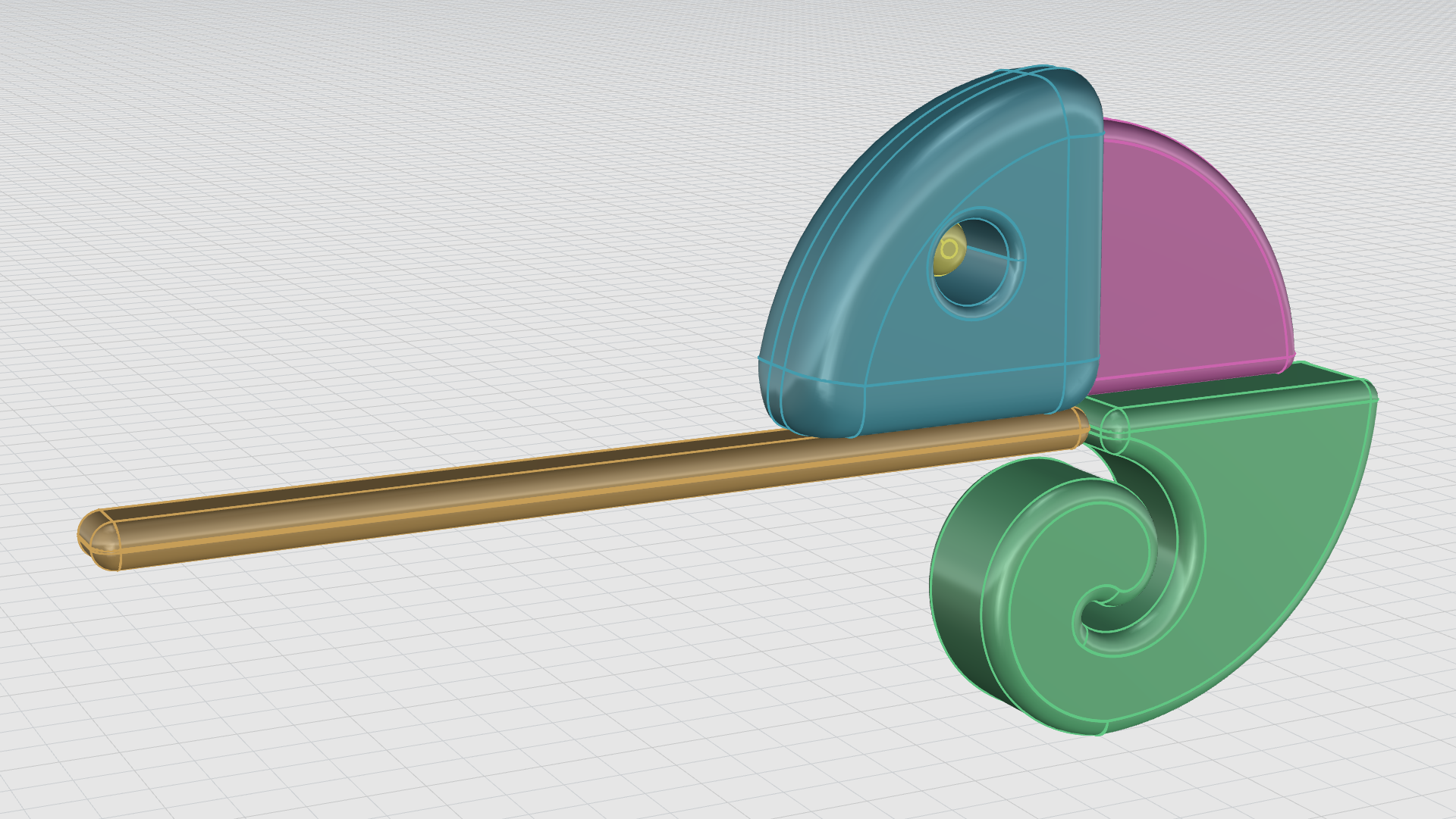
You should now see a result similar to the following:
Chameleon Bubbles
- Maximize the Viewport.
- Make sure the Mid Osnap is enabled.
- Run the
Sphere
command.
- For center of sphere, snap to the midpoint at the end of the tongue.
- For radius, type 0.4. Press Enter.
The following GIF demonstrates the full workflow:
- Maximize the Viewport.
- Make sure the Gumball is enabled.
- Select the sphere.
- Hold down the key to make a copy.
- Using the Gumball red arrow handle, drag the sphere and move it in the z direction.
- Repeat the steps untill you have 4 copies.
- Select the second sphere in the scene.
- Hold down the key and drag the Gumball scale handle to scale the sphere uniformally.
- Move the sphere using the Gumball red arrow to slightly overlap it on the top of the first sphere.
- Repeat the previous steps using the Gumball handles along with the Shift key as needed to manupilate the size and position of each sphere.
The following GIF demonstrates the full workflow:

- Run the
 Group
command.
Group
command. - For Select objects to group drag a window with your cursor from left to right to select all the chameleon parts. Press Enter.
- On the layers panel, make all the layers visible.
Now that all the chameleon parts are grouped together, we need to move the group into our scene using the Gumball move arrows. We will place it on top of the rainbow pipes created earlier, making sure it is properly aligned and visually balanced.
The Base
- Maximize the Viewport.
- Run the
Cylinder
command.
- For Base of cylinder, type 0.
- For Radius, type 8. Press Enter
- For End of cylinder, type -1. Press Enter.
The final outcome should match the image below:
Congratulations! You now have a solid understanding of the solid modeling fundamentals.
This marks the end of the solid modeling tutorial. Throughout this tutorial, we demostrated how to create solids from primitives and from joining simple curves, and now you should have a clear understanding of how to edit and manipulate them using solid editing commands to produce water-tight models.
