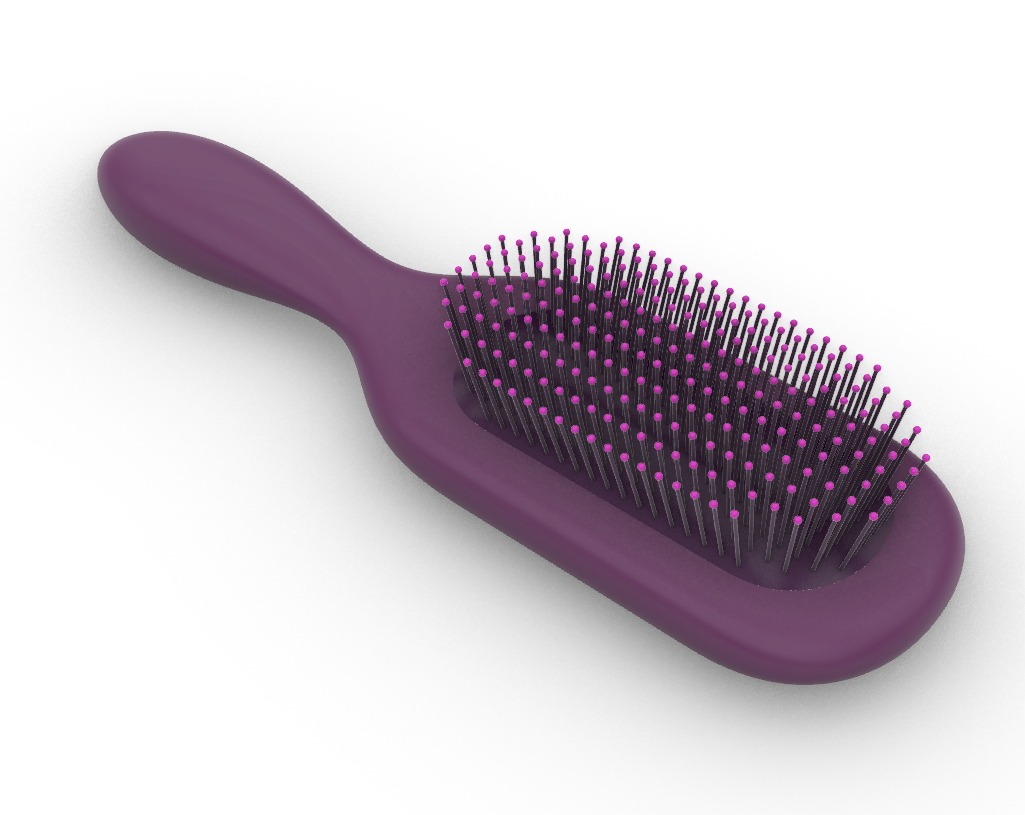
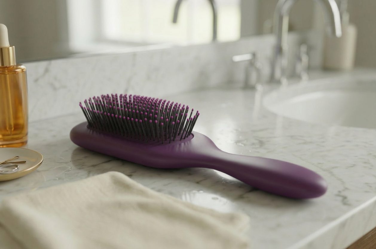
In this tutorial, you’ll learn how to solve simple and complex shapes using Rhino’s  Patch
command. Using Patch to generate 4 and 5-sided surfaces while preserving geometric continuity with adjacent edges, results in smoother flow and cleaner reflections on the final product, whether the model is intended for manufacturing or visualization. We’ll also configure
Patch
command. Using Patch to generate 4 and 5-sided surfaces while preserving geometric continuity with adjacent edges, results in smoother flow and cleaner reflections on the final product, whether the model is intended for manufacturing or visualization. We’ll also configure  Zebra
analysis to clearly evaluate surface transitions, and finish by adding bristles using a parametric
Zebra
analysis to clearly evaluate surface transitions, and finish by adding bristles using a parametric  Grasshopper
definition. Let’s get started!
Grasshopper
definition. Let’s get started!
Create the Handle
In this section, we will create the 5-sided surface for the handle. 5+ sided surfaces are a challenge in
NURBS
modeling, especially when needing to control the flow or continuity to adjacent geometry. Patch
has tools to control continuity on all sides, including on surfaces with unequal edge count and gives you fine-grain control over surface direction and spans.
- Download and open the model Patch Brush.
- Maximize the .
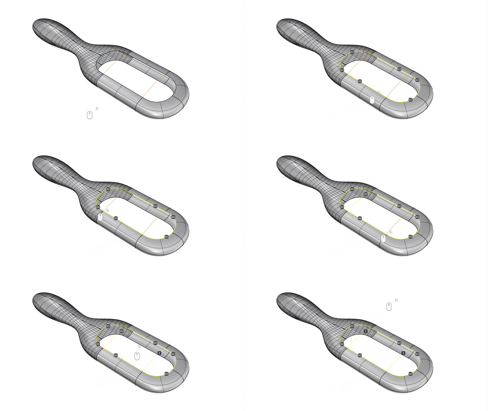
- Run the Patch
command.
- At the
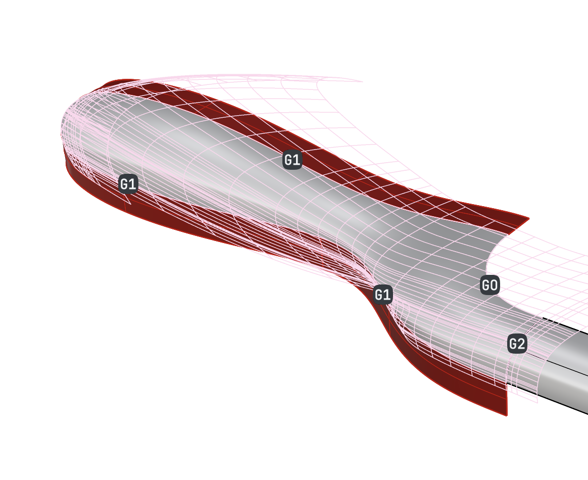
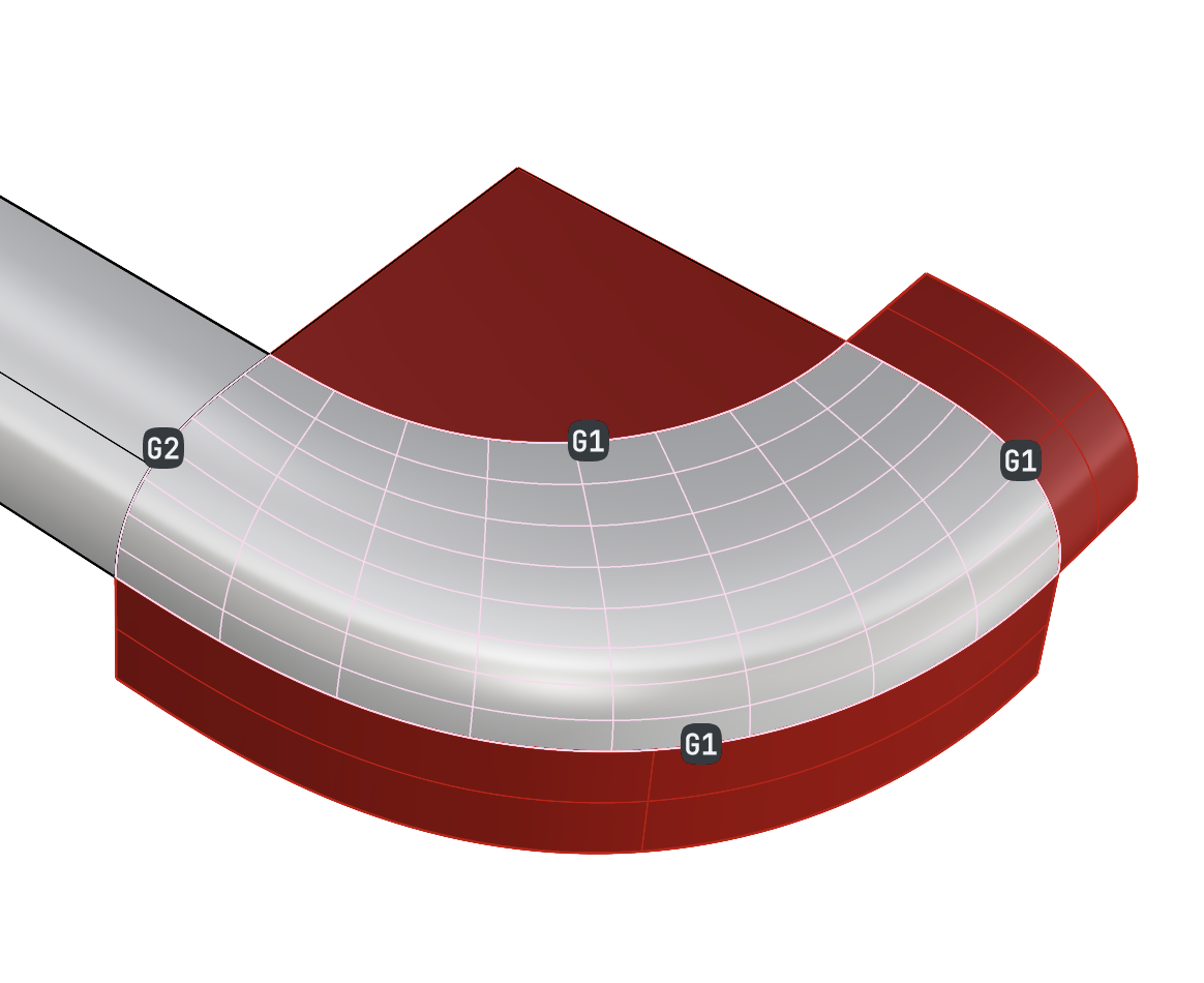
Select edges, curves, meshes, pointclouds and pointsprompt , select the indicated edges and curves: - In the viewport, select the dot that is over the shortest edge to change its continuity to G2 .
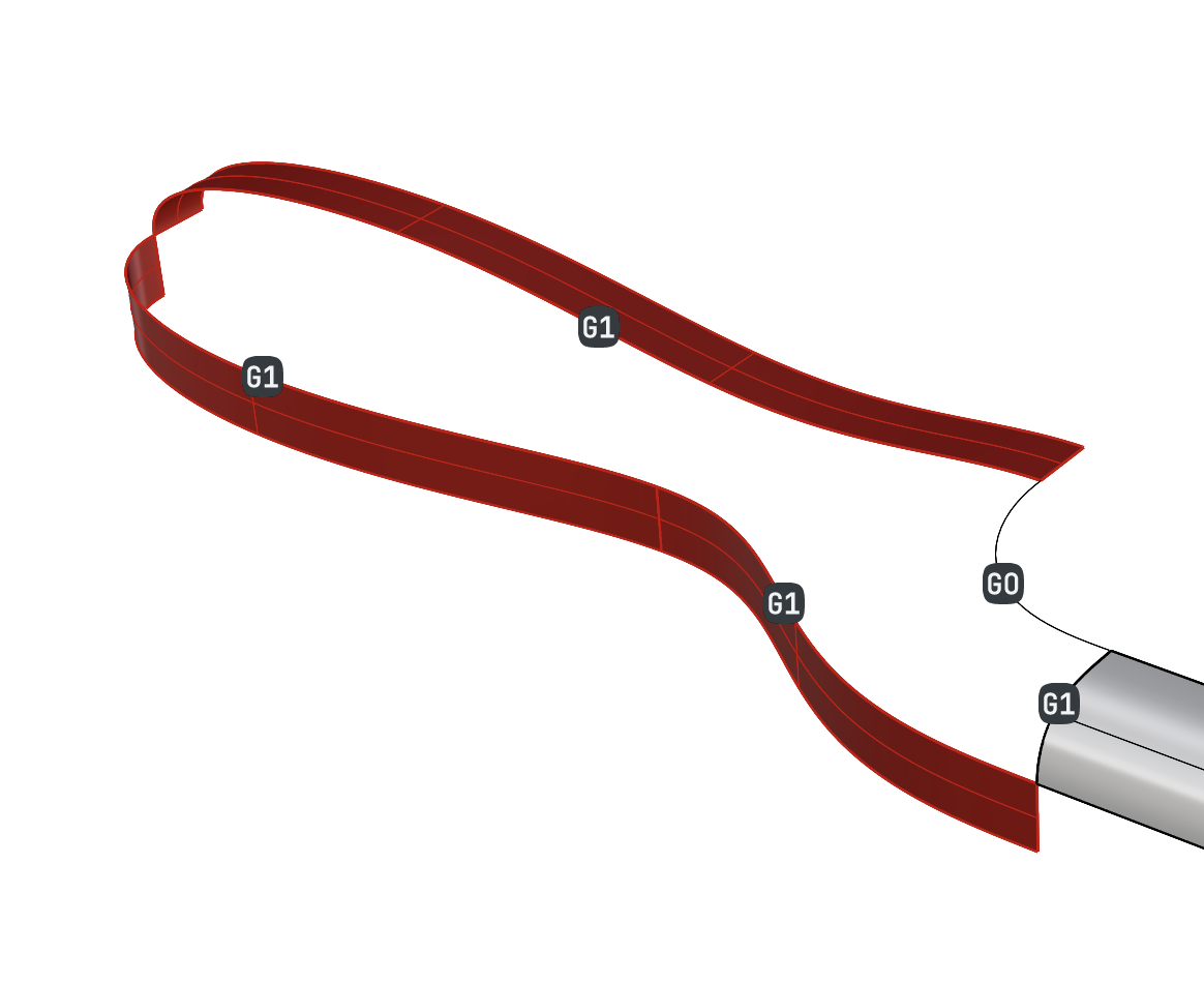
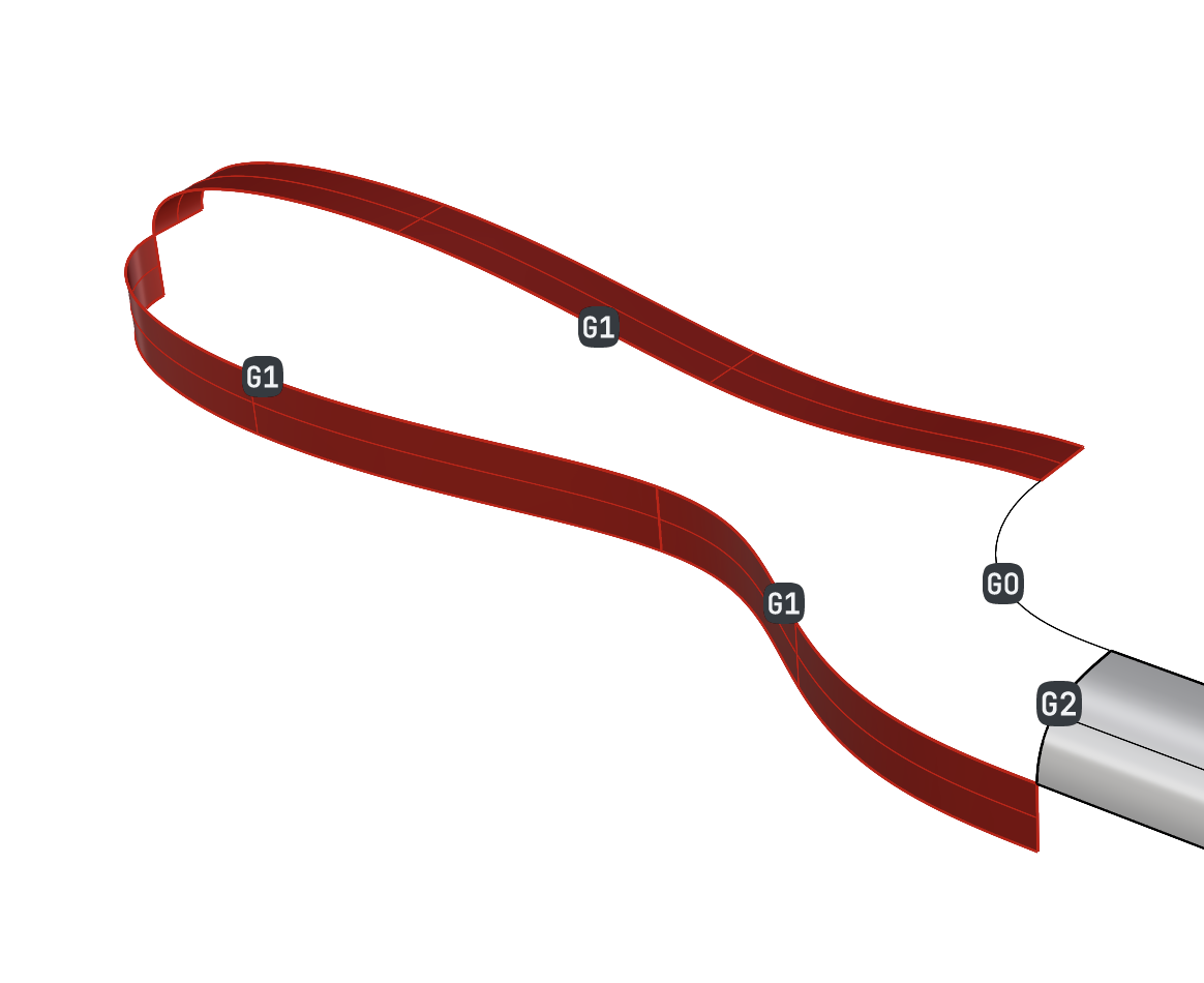
- Right-click to open the Patch dialog:
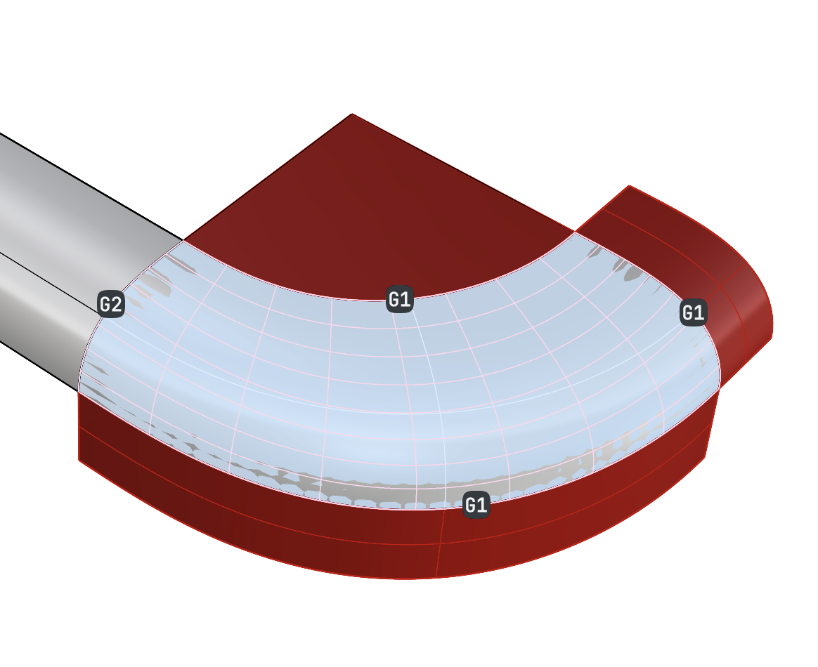
- Change the Domain to
Molded. - Turn on Preview and Refine.
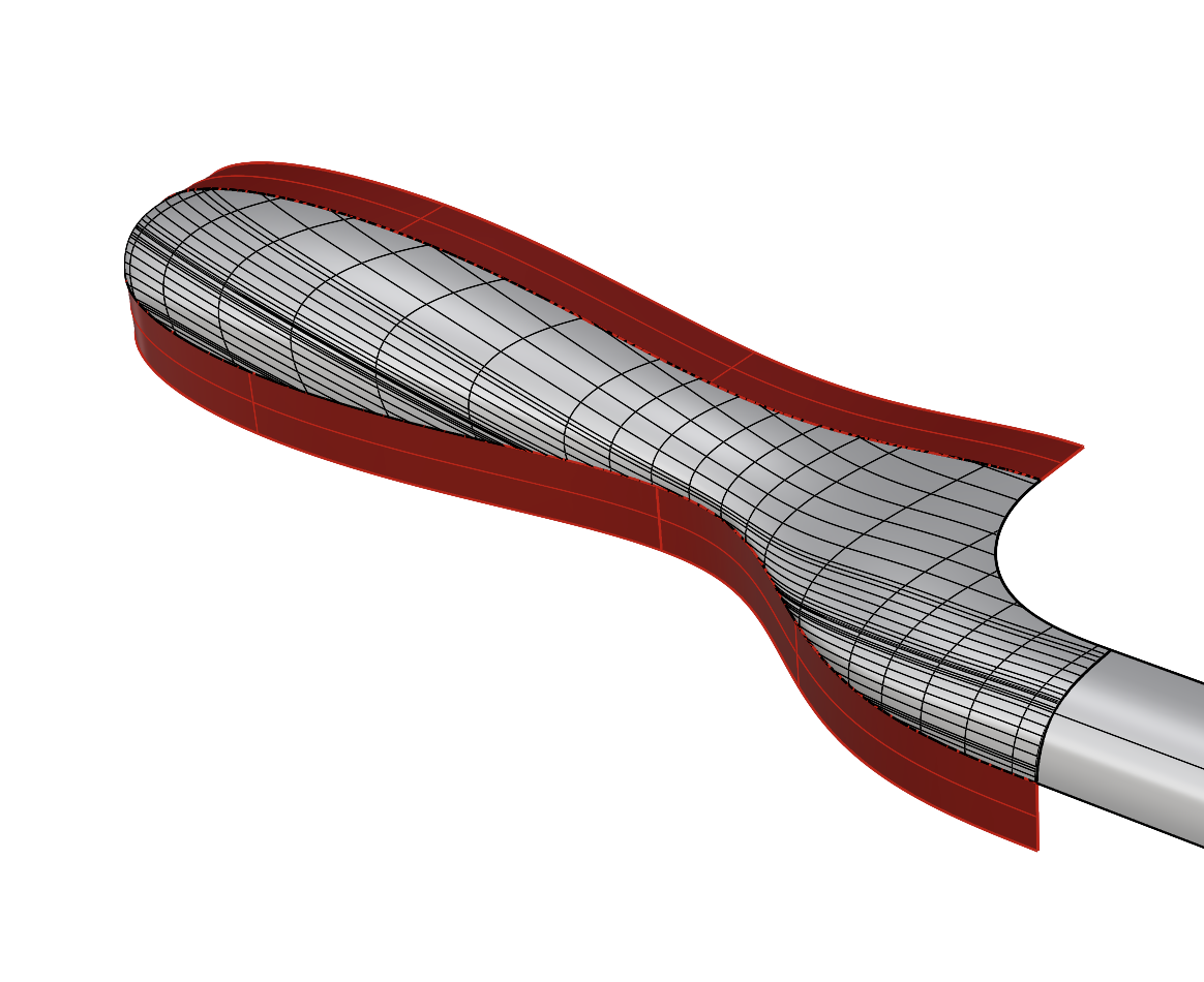
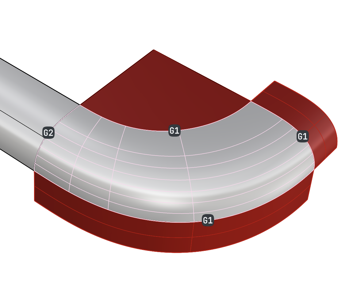
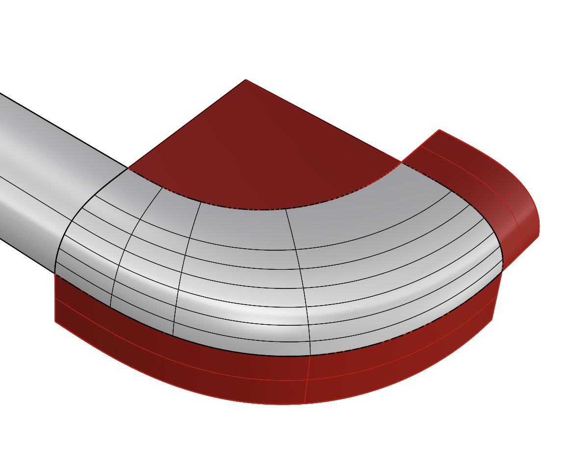
- Press OK to create the Patch:
- Change the Domain to
- Select the patch surface and the side surface of the brush frame.
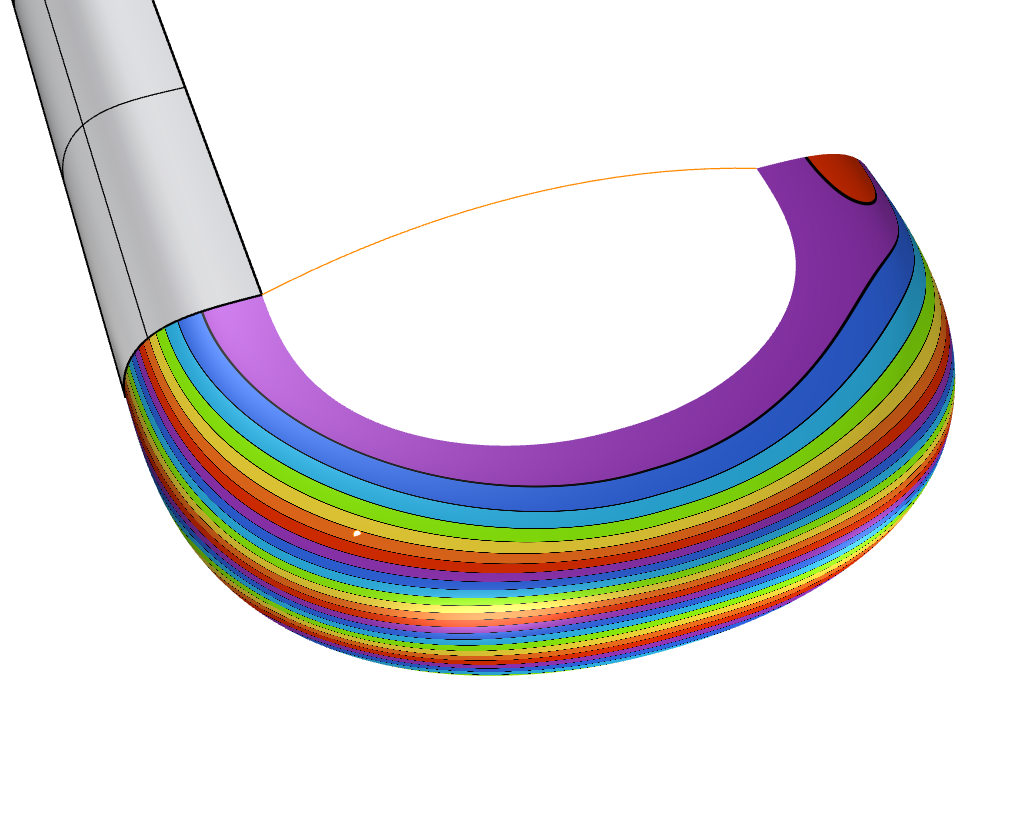
- Run the Zebra
command.
- In the Zebra panel, change Mode to
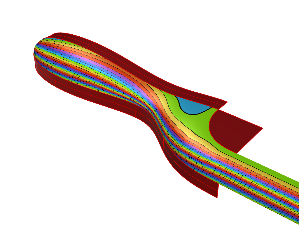
Rainbow. - Notice some irregularities in the Patch surface.
-
Turn on the layer
internal: handle. - Double-click the patch surface to enter the Patch dialog in Edit Mode:
- Select the Constraints button.
- Select the internal curve (orange) as a constraint.
- It will first be marked G0
- Select that label to change it to I , making it an internal constraint.
- Right-click to get back to the Patch dialog.
- Under Tolerances, change
Internal1. - Select OK to create the patch surface. The surface quality is improved.
- In the Zebra panel, select the
 toggle
to deactivate the analysis.
toggle
to deactivate the analysis.
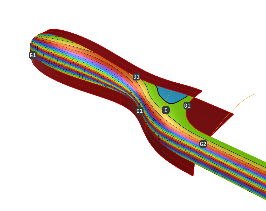
internal: handle curve, guides the patch surface flow and removes some of the wobblyness seen in the initial Patch iteration. Especially, at the junction between the patch and the side surface.Create the Frame
In this section, we will create a 4-sided patch. Also called untrimmed surface, it is the natural way to create
NURBS
surfaces. We could use most
surface from curve
commands for this step. We will continue using Patch
for its flexibility taking a variety of inputs such as points, as well as its powerful history-based editing UI.
- Continue with your file or download patch-brush-frame.3dm.
- Run the Patch
command.
- At the
Select edges, curves, meshes, pointclouds and pointsprompt , select the indicated edges: - Right-click to open the Patch dialog and preview the result:
- In the dialog, press OK to create the surface:
-
Turn off layer
helping-surfaces. - Select the untrimmed patch.
- Run the
 Mirror
command.
Mirror
command. - In the
prompt
, select the
YAxisoption to mirror the surface along the Y-axis. - Select the untrimmed patch and its mirrored copy.
- Run the Zebra
command.
- Set the Mode to
Rainbowif it’s not already. - Double-click the original (left) patch surface to enter Edit Mode.
- Turn on the layer
internal: frame. It contains a point object. - In the dialog, select the Constraints button.
- Select the point object. Points will always be internal automatically.
- Right-click to validate.
- In the dialog, press OK to create the patch surface. We now have a better surface flow where the surfaces meet.
- In the Zebra panel, select the toggle
to deactivate the analysis.
 DragStrength
set to 10 or lower.
DragStrength
set to 10 or lower.Complete the Body
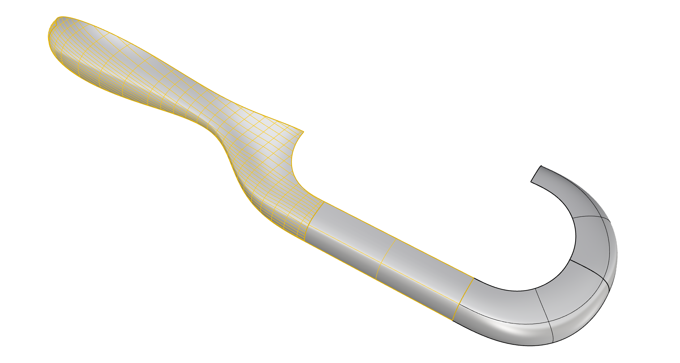
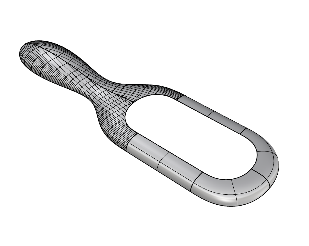
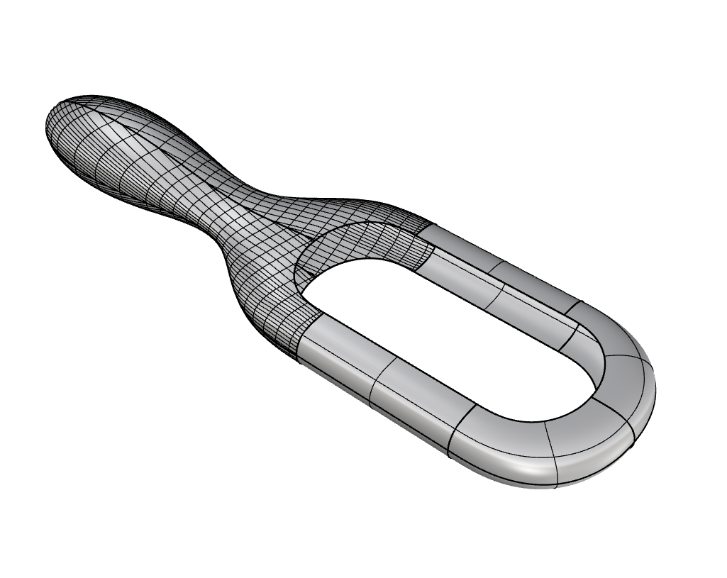
As a brush is essentially a symmetric product, in a simple two-step mirroring of the surfaces, we will obtain all the geometry that represents the brush’s main body. This includes the handle and frame surfaces.
- Continue with your file or download patch-brush-body.3dm.
-
Turn off
all
internal:layers. - Select the handle and side surface
- Run the Mirror
command.
- In the
Command Prompt
, select the
YAxisoption. - Select all surfaces this time.
- Run the Mirror
command again.
- In the Command Prompt , select the ZAxis option.
Create the Soft Cushion
In this section, we will use Patch
once more. It will help us create a puffed surface that represents the cushion holding the bristles. It will meet at a hard angle or G0 to its adjacent surface edges. This will help create the visual separation between the body and the cushion as distinct parts of the brush.
- Continue with your file or download patch-brush-cushion.3dm.
- Make
cushionthe current layer . -
Turn on layer
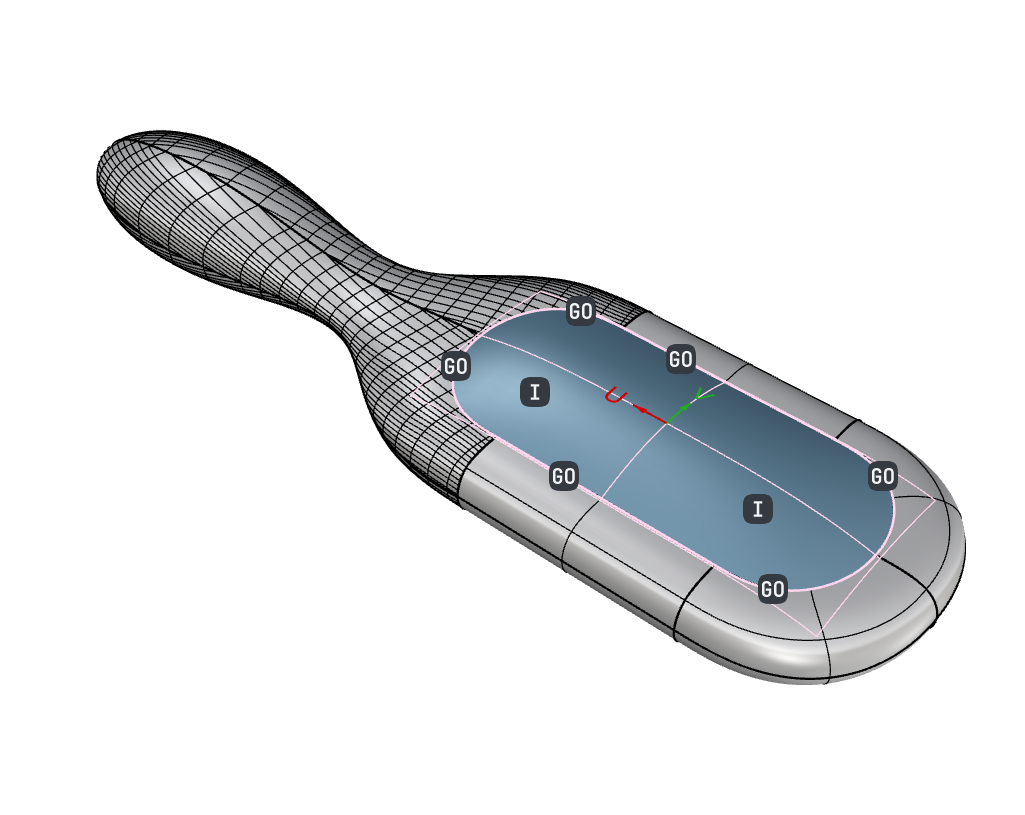
internal: cushion. - Run the Patch
command.
- Double-click to select the loop of edges.
- Shift-click on one continuity dot until they are all set to G0 .
- Select the two internal curves (orange).
- Set the internal curve dots to I .
- Press to bring up the Patch dialog.
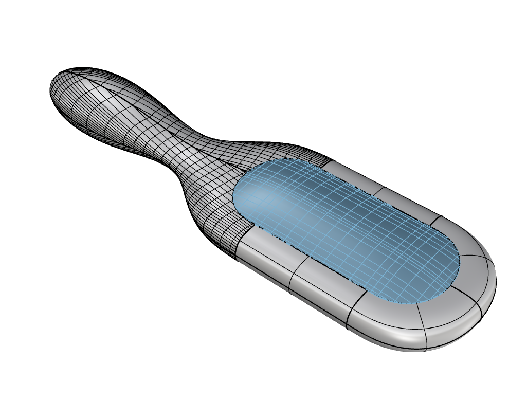
- The Domain should automatically be set to Projected.
- Turn on Refine and press OK to create the patch.
Add the Bristles
In this section, we’ve prepared a Grasshopper
definition to automatically add the bristles to the cushion surface. The main advantage of creating it in Grasshopper is that the bristles can be adjusted parametrically. Play with the sliders in the definition to adjust length and radius.
- Continue with your file or download patch-brush-bristles.3dm.
- Run Grasshopper
. It will open the canvas.
- Download and open patch-brush.gh.
- The definition should automatically pick up the cushion patch, use the points in the pts layer, and generate the bristles.
- In the Grasshopper canvas, modify the
LineorRadius Number Slider
.
Number Slider
. - Set the
to
RaytracedDisplay Mode