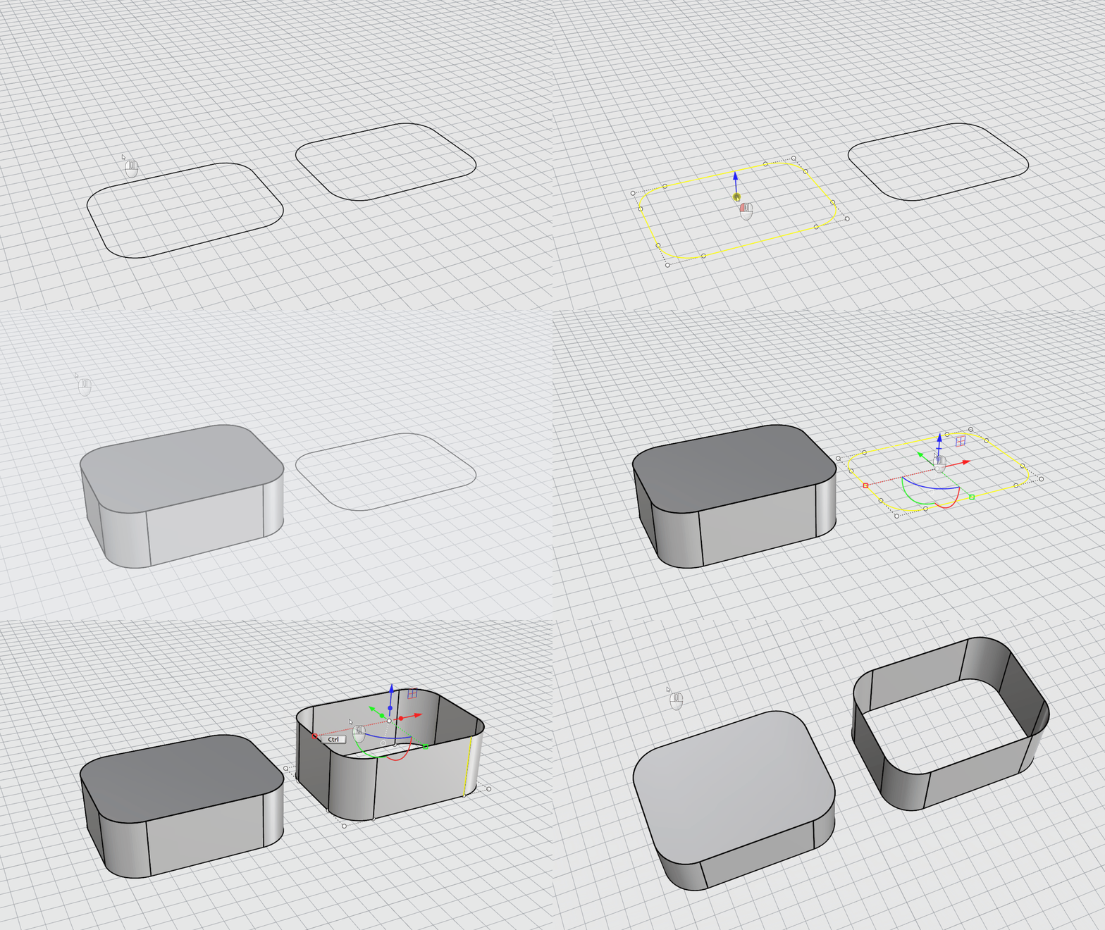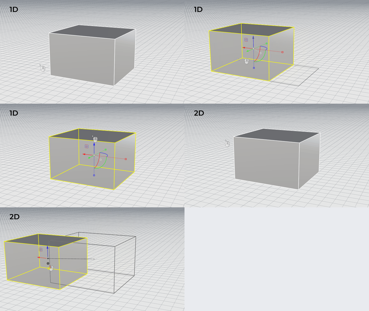
A 3D scan gives you a dense, noisy mesh. It’s not a model you can hand off for manufacturing, analysis, or further development. This tutorial reconstructs the front fender and hood of a scanned car body as eight clean, continuity-matched surfaces, using a handful of Rhino 9’s new surfacing tools:  Rebuild
to fit curves to the scan,
Rebuild
to fit curves to the scan,  Gumball: Control Polygon
to massage control points directly on the surface, and
Gumball: Control Polygon
to massage control points directly on the surface, and  SoftTransform
to keep neighboring surfaces from drifting apart while you do it.
SoftTransform
to keep neighboring surfaces from drifting apart while you do it.
What you'll learn
- Fit curves to a noisy scan and refine them with Rebuild
’s rebuild to tolerance option.
- Massage control points directly on the surface with Gumball Control Polygon
alignment, and keep neighboring surfaces from drifting apart using SoftTransform
.
- Chain surfaces together with
 EdgeSrf
and
EdgeSrf
and  MatchSrf
, then verify the result with
MatchSrf
, then verify the result with  GlobalEdgeContinuity
and
GlobalEdgeContinuity
and  Zebra
.
Zebra
.
Get Started
- Download and open the reference.3dm file. It contains the scanned mesh and nothing else. Every curve and surface in this tutorial gets built from scratch.
- Make sure the Mesh
Osnap
(
 SnapToMeshObject
) is enabled and the
SnapToMeshObject
) is enabled and the Meshlayer is unlocked. You’ll be pulling and projecting onto the scan constantly, and bothPullandProjectneed to be able to snap to it.
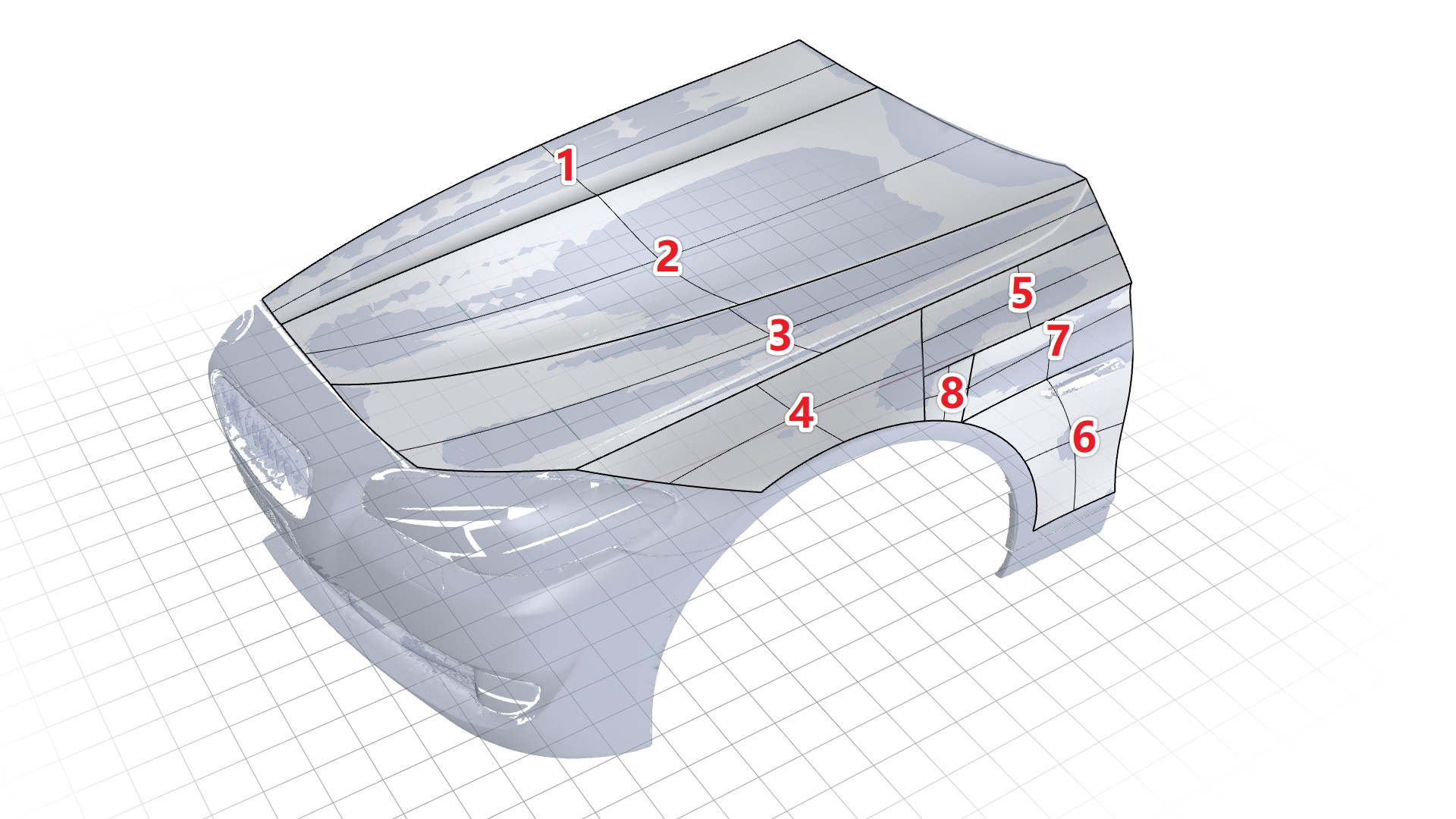
This tutorial builds the panel as eight separate surfaces, shown below. Work through them roughly in order. Later, we will match a surface’s continuity against the ones before them.
Throughout, you’ll check each surface against the scan using cross-section curves generated in Grasshopper, comparing the mesh’s cross-sections (plum) against the surface’s (green) as you adjust control points.
The first surface
- Download and open the reference.3dm file. It contains the scanned mesh and nothing else. Every curve and surface in this tutorial gets built from scratch.
- Run
 InterpCrv
with
InterpCrv
with Degree=5andKnots=Uniform, and enable the Vertex Osnap . Click four points on the mesh to draw the first free-form curve. - Run
 SetPt
and align it to
SetPt
and align it to Y=0, the panel’s symmetry line. Make sure to setCopy=Yesin the prompt . - Run
 EditPtOn
on the aligned copy to turn on its edit points,
EditPtOn
on the aligned copy to turn on its edit points, - Select all the edit points, then use
 Pull
to pull them back onto the mesh. Set
Pull
to pull them back onto the mesh. Set DeleteInput=Yes. - Select the pulled curve and use Gumball Extrude along the positive Y axis, to create a surface.
- Run
 Loft
, using the edge of the extruded surface and the curve from step 1 as the two rail curves. Check Match start tangent.
Loft
, using the edge of the extruded surface and the curve from step 1 as the two rail curves. Check Match start tangent.
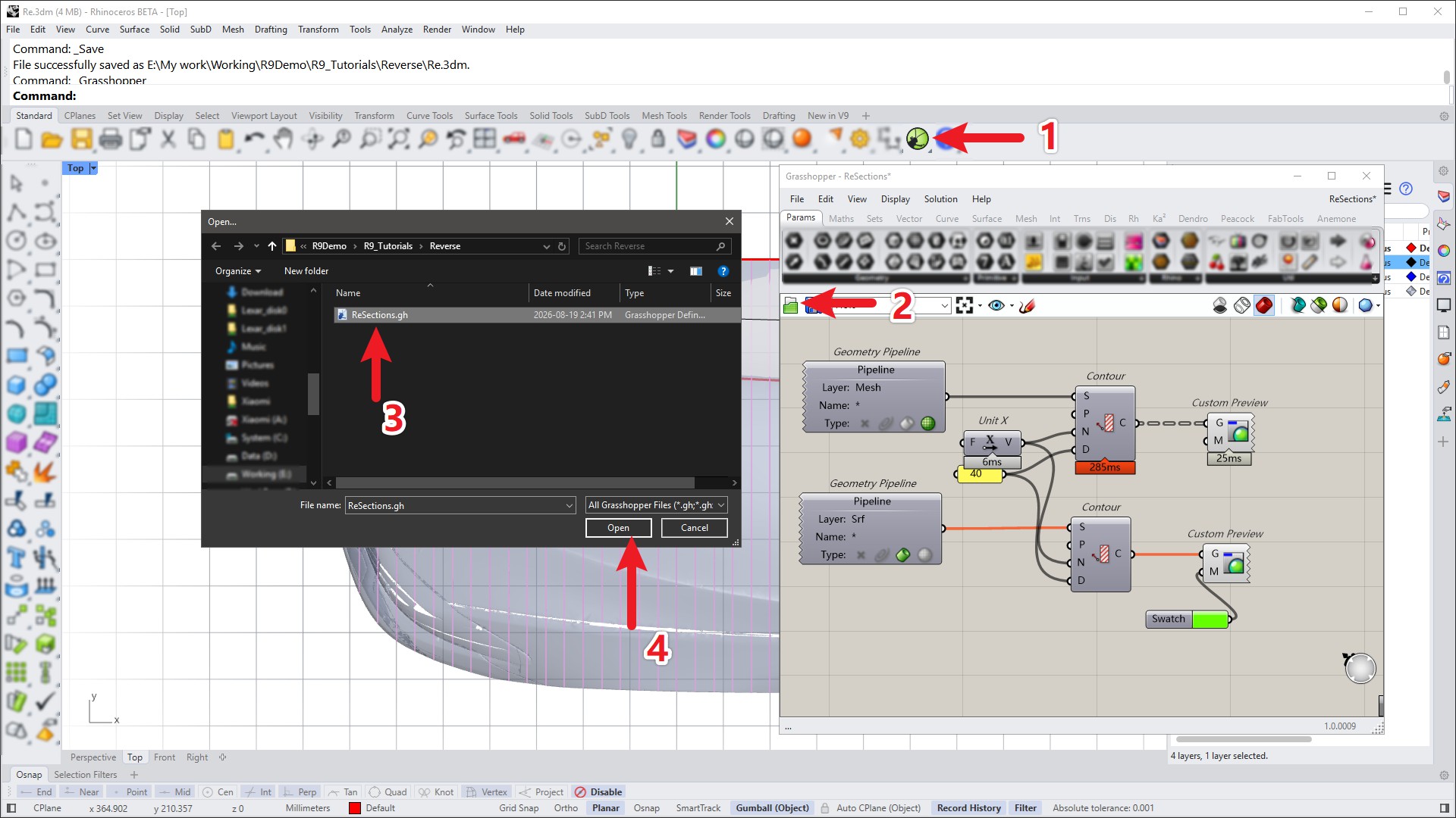
- To check the surface against the scan, open cross-sections.gh in Grasshopper. It displays cross-section curves through both the mesh and the surface so you can compare them directly. Double-click the Grasshopper window’s title bar to roll it up out of the way once it’s running.
- Run
 ChangeDegree
and set the surface’s U-direction degree to 4. Turn on its
Control Points
and use
Gumball Move
to adjust their heights, keeping the surface’s cross-section curves (green) as close as possible to the mesh’s (plum).
ChangeDegree
and set the surface’s U-direction degree to 4. Turn on its
Control Points
and use
Gumball Move
to adjust their heights, keeping the surface’s cross-section curves (green) as close as possible to the mesh’s (plum).
The second surface
This time around we will build a surface from 4 curves using EdgeSrf
.
The method here is similar to the first surface: draw curves, build a surface between them, then adjust control points until the surface’s cross-sections match the mesh’s.
We will reuse the edge curve of the surface created in step one, which will be adjacent to this surface.
- Continue with your file or download and open the Re-01.3dm file.
- Run InterpCrv
(
Degree=5,Knots=Uniform) with the Vertex Osnap to draw the curve running over the hood in Y direction. - Run InterpCrv
(
Degree=5,Knots=Uniform) again to draw the next curve, on the window side of the hood (this curve’s end point should be at the end of the first surface’s edge) - Use
 Extend
to lengthen the curves until they visually intersect in top view, then
Extend
to lengthen the curves until they visually intersect in top view, then  Trim
away the extra segments past the intersection. Turn on their control points and use
Trim
away the extra segments past the intersection. Turn on their control points and use  Move
to make the two endpoints coincide exactly.
Move
to make the two endpoints coincide exactly. - Draw a third curve on the front side of the hood, connecting the left endpoints of the first curve and the end of the edge of the first surface.
- Run EdgeSrf
, selecting the three curves and the adjacent edge, to create the second surface.
- Open the SoftTransform
panel (
Windowsmenu:Panels>SoftTransform). Enable Enabled and Boundary constraints, and set the edge shared with the first surface to G0. - Use the Radius parameter to set Soft Transform’s falloff range to about 120, then adjust the second surface’s control points row by row along the V direction. Just as before, aim to keep the surface’s cross-sections as close as possible to the mesh. This step takes patience and usually a few passes.
- Switch to the Top viewport and use
 Curve
to draw a trim curve, then trim away the part of the surface that extends past the reference mesh.
Curve
to draw a trim curve, then trim away the part of the surface that extends past the reference mesh.
The third surface
Like the second surface, the third is a five-sided patch rather than a four-sided one: build a four-sided surface that covers the whole region first, then trim it down to size.
- Continue with your file or download and open the Re-02.3dm file.
- Run InterpCrv
with the Vertex
Osnap
to draw two curves, and use the same extend/trim/coincide process as step 2 to join their endpoints.
- Run InterpCrv
once more to draw a short connecting curve, then run EdgeSrf
to create the third surface.
- Run
 PointsOn
to turn on the surface’s control points.
PointsOn
to turn on the surface’s control points. - In the SoftTransform
panel, set the edge shared with the second surface to G0.
- Switch the
 Gumball Settings
from
Gumball Settings
from Align to CPlanetoAlign to Control Polygon. This aligns the Gumball arrows with the control point’s own U, V, and N (surface normal) direction instead of the world axes. Adjust the control points row by row along N, again matching the surface’s cross-sections to the mesh’s. This still takes patience. - Use Curve
to draw a trim curve and trim away the part of the surface beyond the reference mesh.
The side surfaces
The creation method for the side surfaces is basically the same as before: Create surfaces and then adjust their shapes. They have a distinct characteristic: They smoothly transition from the top surface to the circular hub cap.
- Continue with your file or download and open the Re-03.3dm file.
- In the Front viewport, run
 Circle
to draw a full circle.
Circle
to draw a full circle. - Use
 SubCrv
to keep only half of it.
SubCrv
to keep only half of it.  Project
the half-circle onto the reference mesh.
Project
the half-circle onto the reference mesh.- Rebuild
to rebuild it to degree 5 with 6 control points.
- Move the result -2 units along Y with Gumball Move . This pulls it slightly away from the radius.
- Run InterpCrv
to draw two more curves, then EdgeSrf
to create the fourth surface. Turn on its control points with PointsOn
and refine the shape with Gumball, as with the previous surfaces.
- Use
 Line
to draw the fifth surface’s side edge and Extend
to lengthen it.
Line
to draw the fifth surface’s side edge and Extend
to lengthen it. - Draw the fifth surface’s long edge with InterpCrv
 Match
this curve curvature-continuous (G2) with the adjacent fourth surface’s edge.
Match
this curve curvature-continuous (G2) with the adjacent fourth surface’s edge.- Run EdgeSrf
to create the fifth surface.
- Use MatchSrf
to make its left side curvature-continuous with the fourth surface. Enable the following two options: Match by closest points and Preserve isocurve direction.
- Turn on its
Control Points
and adjust with Gumball. In SoftTransform
, set the fifth surface’s left edge to G2 and its top edge to G0 so both stay constrained while you edit.
- The sixth surface is flatter and simpler. In the Front viewport, draw two straight lines.
 Unlock
the
Unlock
the Meshlayer.- Project
the two curves onto the reference mesh.
- Rebuild
both to degree 5 with 6 control points. The vertical curve will need its own control point tweaks; temporarily disable SoftTransform while you do that.
- Match
and Move
to connect every curve endpoint with G0 continuity.
- Finally, create the sixth surface with EdgeSrf
and tune as before using
Gumball Move
, with SoftTransform enabled.
The final two surfaces
The last two surfaces need relatively little adjustment compared to the rest.
- Continue with your file or download and open the Re-04.3dm file.
- Run InterpCrv
to draw a straight line.
- Run EdgeSrf
to create the seventh surface.
- Run MatchSrf
to make the seventh surface’s bottom edge curvature continuous with the sixth surface’s top edge. Turn on its
Control Points
control points and adjust with
Gumball Move
. Constrain both the top and bottom edges this time, since both are shared with a neighbor.
- Run EdgeSrf
once more to create the eighth and final surface. It needs little to no adjustment.
- Run GlobalEdgeContinuity
and window-select the fourth through eighth surfaces. Notice that the eighth surface currently only has G0 continuity with its neighbors.
- Run MatchSrf
to make the eighth surface’s right side curvature-continuous with the seventh surface’s left side, then again to match its left side to the fourth surface’s right side.
Matching several edges at onceThe eighth surface’s other two edges only need G0 continuity with their neighboring surfaces and curves. Since you’re matching several edges at once, the
MultipleMatchesoption lets you pick them all in a single MatchSrf
run instead of repeating the command. - Run Zebra
and
 EMap
to check the smoothness of the finished surfaces.
EMap
to check the smoothness of the finished surfaces.
Detail adjustments
With all eight surfaces built and matched, go back over the panel and refine the local fit where it needs it. Use SoftTransform
’s boundary constraints to lock in the continuity you’ve already established between surfaces, then use Gumball to nudge control points until every cross-section, mesh and surface alike, lines up. Re-check with GlobalEdgeContinuity
as you go. You can continue with your file or download and open the Re-05.3dm file.