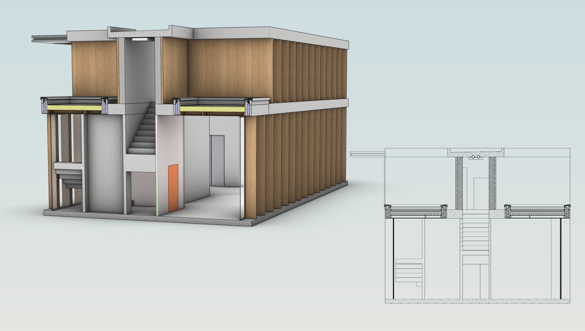
In this tutorial, you’ll learn how to configure and create building sections in Rhino 9. Using the  ClippingSections
and
ClippingSections
and  ClippingDrawings
commands, you’ll cut vertical and horizontal sections through a model and extract them as 2D drawings with clean, consistent linework, then set up reusable Section Styles to control hatch patterns, linetypes, and colors across every drawing. Clipping properties can be tuned at any stage, from a rough working section to a finished, printable sheet. Let’s get started!
ClippingDrawings
commands, you’ll cut vertical and horizontal sections through a model and extract them as 2D drawings with clean, consistent linework, then set up reusable Section Styles to control hatch patterns, linetypes, and colors across every drawing. Clipping properties can be tuned at any stage, from a rough working section to a finished, printable sheet. Let’s get started!
What you’ll learn
- Create a section with ClippingSections
.
- Create a 2D drawing with ClippingDrawings
.
- Set up a Layout for printing.
- Create reusable Section Styles and control hatch scale.
- Create horizontal sections and clean up unused layers with
 Purge
.
Purge
. - Control the layer and display properties of Clipping Drawings.
- Align 2D section drawings with
 AlignClippingDrawings
.
AlignClippingDrawings
.
Create a Section
We’ll start by creating a Clipping Plane through the model with ClippingSections
, then use its widget to preview the cut interactively.
- Download and open the model Section Tutorial.
- Maximize the viewport and Change Display Mode to Shaded.
- Run ClippingSections
.
- At the
Select objects to sectionprompt , press to select all the geometry. - At the
Place sectionsprompt, set the following options:- Direction =
Y - Custom Depth =
No - Clip =
No - Name =
Vertical - Label Mode =
Text - Saved to Named View =
No - Flip =
Yes
- Direction =
- Place the section, snapping to the vertical guide. Press Enter.
-
Minimize
the Perspective to get back to
 4View
.
4View
. -
Select
the Clipping Plane widget and open the
 Properties
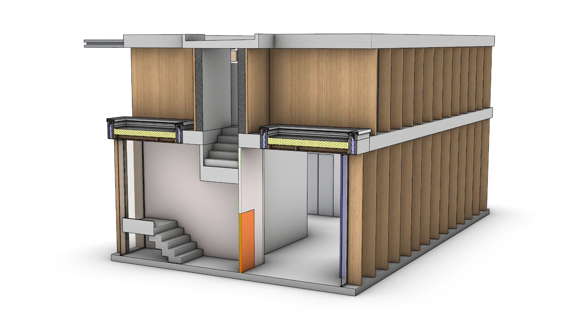
panel. Under Views Clipped, check Perspective.
Properties
panel. Under Views Clipped, check Perspective. - In the viewport, drag the Clipping Plane widget left and right. Notice how the clipped view updates in the viewport.
Create a 2D Drawing
Next, we’ll extract a 2D vector drawing of the section using ClippingDrawings
.
- Download and open the model Section Tutorial 01 or continue with the file above.
- Run ClippingDrawings
to create a new 2D Drawing.
- At the
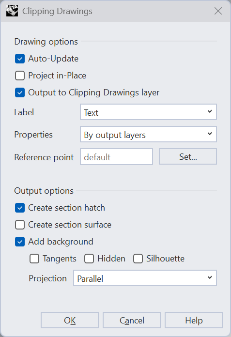
Select clipping planesprompt, select theVertical_00section and press . - In the Clipping Drawings dialog, select the following options:
- Auto-Update =
Yes - Project in Place =
No - Output to Clipping Drawings layer =
Yes - Label =
Text - Properties =
By Output Layers - Create Section Hatch =
Yes - Create Section Surface =
No - Add Background =
Yes - Tangents =
No - Hidden =
No - Silhouette =
No - Projection =
Parallel
- Auto-Update =
- Press OK to confirm. We’ll cover these Clipping Drawing options in more detail later in this tutorial.
- At the
Placement pointprompt , place the drawing in the viewport, to the right of the model. - The drawing is created. This is a parallel section looking through the clip visible in the viewport.
- In the viewport, drag the Clipping Plane widget again. Notice how both the 2D Drawing and the clipped view update together.
Create a Layout
Rhino’s Layouts (sometimes called Sheets in other software) are where you arrange 2D Drawings for printing.
- Download and open the model Section Tutorial 02 or continue with the file above.
- Run
 Layout
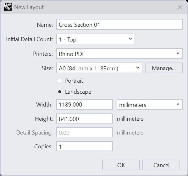
. In the New Layout dialog, set:
Layout
. In the New Layout dialog, set:
- Name =
Cross Section 01 - Initial Detail Count =
1 - Top - Printer =
Rhino PDF - Size =
A0 (841mm x 1189mm), Landscape - Copies =
1
- Name =
- The new Layout opens, and a viewport tabs is added at the bottom of the screen so you can switch between Model Space and Layout Space (also called Paper Space in other software).
- Switch to
Cross Section 01using the viewport tabs. - Double-click inside the
 Detail
to activate the Detail. A Detail is essentially a window into Model Space from your Layout or “sheet”.
Detail
to activate the Detail. A Detail is essentially a window into Model Space from your Layout or “sheet”.
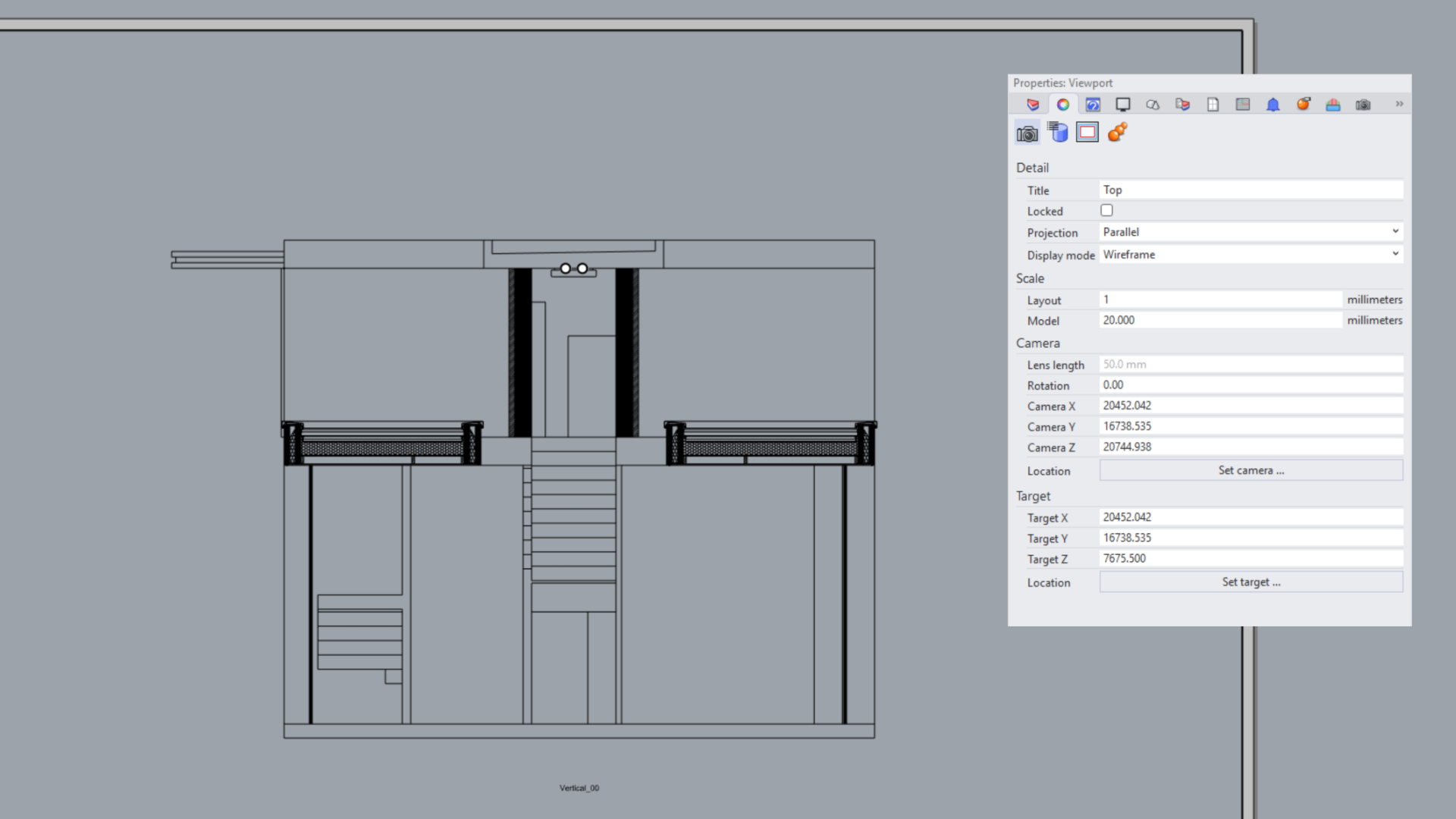
- Pan and zoom to center the 2D Drawing in the Detail.
- Double-click outside the Detail to deactivate it.
- Select the Detail border.
- In the Properties
panel, set:
- Scale Value = Layout
1/ Model20(1:20 scale), - Check Locked so the scale can’t change while navigating in an open Layout view.
- Scale Value = Layout
Create Section Styles
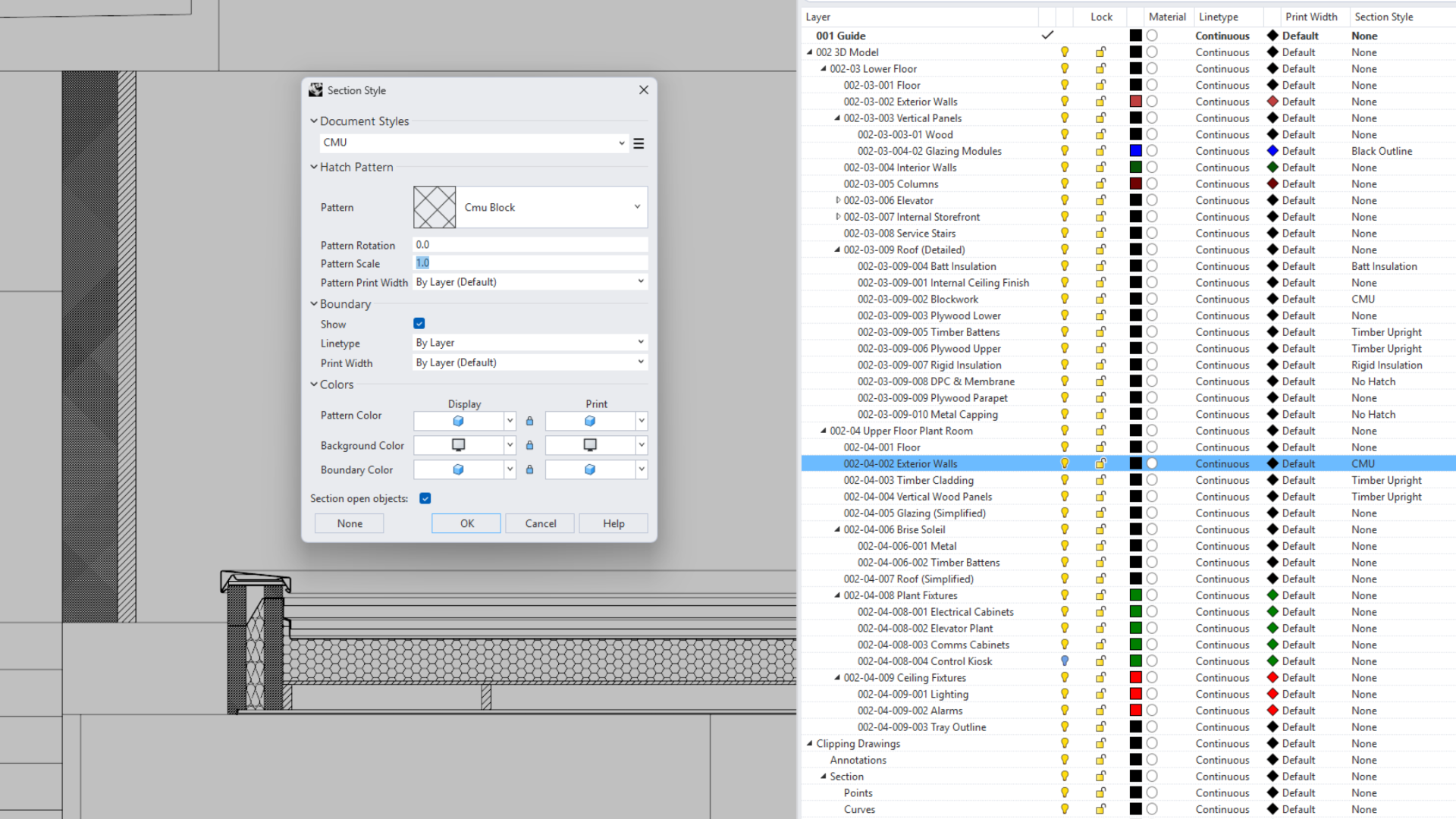
Each layer’s Section Style controls its hatch pattern, linetype, and color for both Print and Display, and applies to clipped views as well as 2D Drawings. Hatch scale can be set relative to either Model Space or Layout Space. Here we’ll use Layout Space, so the hatches look right on the printed sheet. In Cross Section 01, the blockwork hatch currently looks very dense, so let’s adjust it.
- Download and open the model Section Tutorial 03 or continue with the file above.
- Open the
 Layer
panel:
Layer
panel:
- Find
002-04-002 Exterior Wallslayer. - Scroll to its Section Style column:
CMU. -
Select
CMUto open the Section Style dialog.
- Find
- In the dialog:
- Change Pattern Scale from
1to4. - Select the hamburger menu (☰) and choose Save Changes.
- Press OK.
- Change Pattern Scale from
- The 3D section updates immediately. To update the 2D Drawing, run
 UpdateClippingDrawings
and choose
UpdateClippingDrawings
and choose All. Every layer using theCMUSection Style updates together. - Switch back to the viewport and Zoom into the clipped model. The section hatches now look too large. Rhino scales hatches in Model Space using a separate multiplier.
- Run
 HatchScale
and, at the
HatchScale
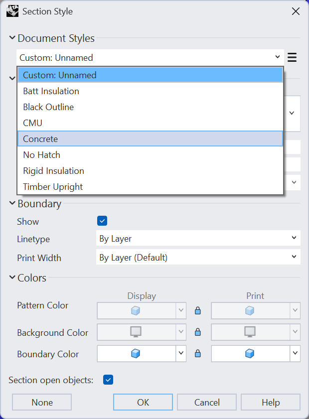
and, at the Model space hatch scaleprompt , change the value from50to30. Note the improvement. - Rhino 9 ships with an extensive hatch library. Let’s add a new Section Style. In the Layers panel, select
002-03-001 Floorand select None in the Section Style column. - In the Section Style dialog, select:
- No Hatch Pattern to browse the hatches already loaded in the file.
- Press the + next to Search to open the hatch library.
- Find
Concreteand double-click to add it to the document. - Set Pattern Scale to
1.0and save the style asConcrete.

-
Apply the
ConcreteSection Style to the following layers too:002-04-001 Floor002-04-007 Roof (Simplified)
-
The 3D model updates immediately. Run
UpdateClippingDrawings
and choose Allto update the 2D Drawings. -
Fine-tune the hatch scale and pattern scale as needed to balance Model Space and Layout Space.
Create Horizontal Sections
We’ll now repeat the process to create a horizontal section.
-
Download and open the model Section Tutorial 04 or continue with the file above.
-
Let’s clear out what we no longer need. Right-click the
Cross Section 01tab at the bottom of the screen and choose Delete. -
Select and delete the 2D Drawing in the viewport, then select and delete the Clipping Plane widget.
-
Deleting objects leaves unused layers and block instances behind. Run
Purge
and check every option in the dialog to clean up the file. Press OK. -
Maximize the viewport and change Display Modes to Shaded.
-
Enable Ortho .
-
Run
ClippingSections
. -
At the
Select objects to sectionprompt , press Enter. to select all the geometry. -
At the
Place sectionsprompt, set:- Direction =
World - Custom Depth =
No - Clip =
No - Name =
Horizontal - Label Mode =
Text - Saved to Named View =
No - Flip =
No
- Direction =
-
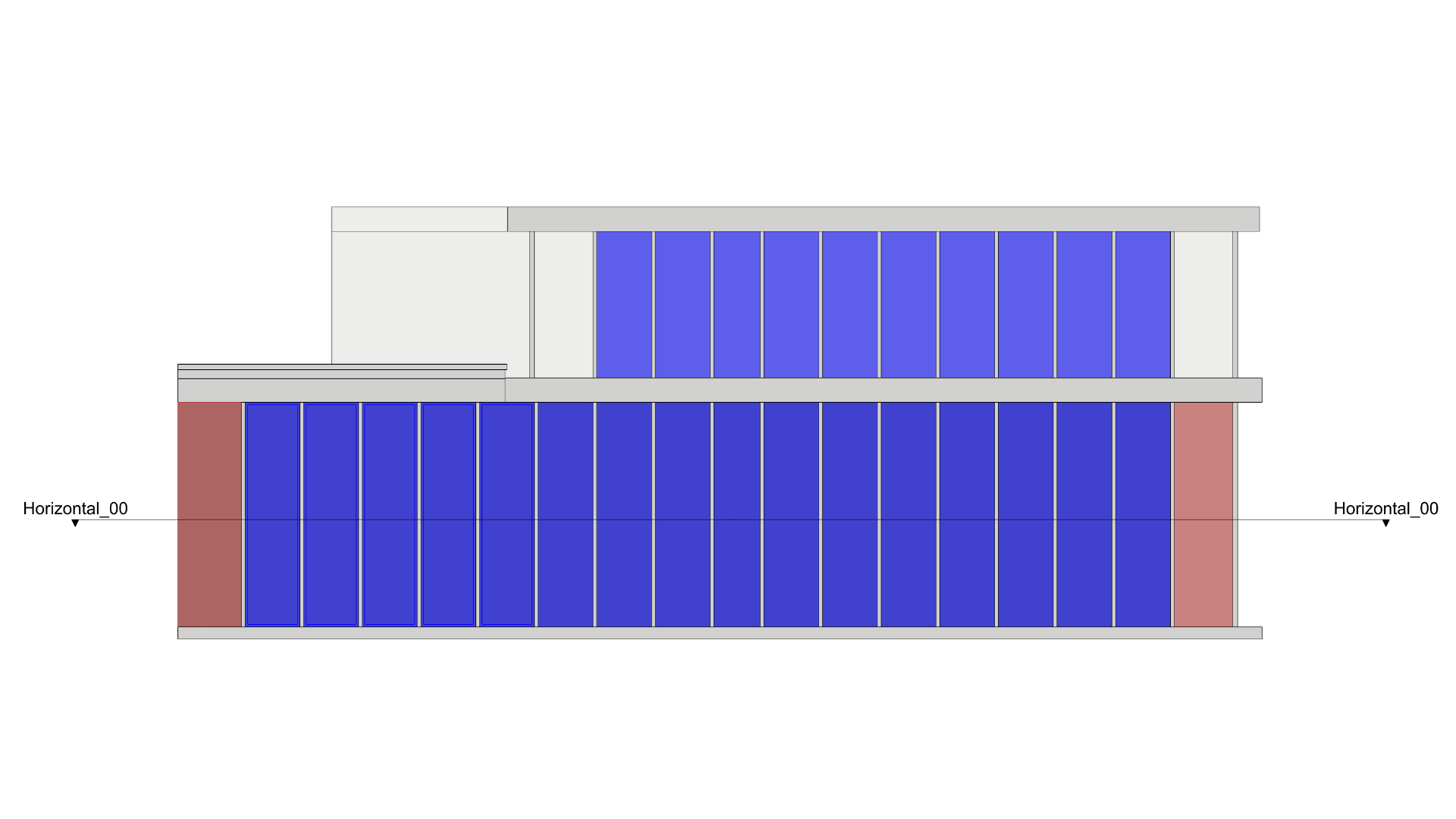
Place the section about halfway up the lower floor. Press Enter.
-
Run
ClippingDrawings
to create a new 2D Drawing. -
At the
Select clipping planesprompt, select theHorizontal_00section and press Enter. -
Set the same Clipping Drawings options used earlier and press OK.
-
At the
Placement pointprompt, place the drawing in the viewport, to the right of the model.
Align Section Drawings
Use Source Layers is especially useful while sections are still part of the design process, rather than a finished deliverable. Let’s try it.
- Download and open the model Section Tutorial 05 or continue with the file above.
- Run Purge
to clear out the unused
Clipping Drawingslayers left over from the previous section. - Maximize viewport.
- Enable Ortho .
- Run the
 Copy
command.
Copy
command. - At the
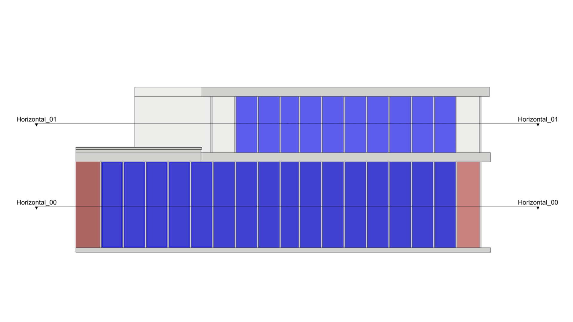
Select objects to copyprompt , select theHorizontal_00Clipping Plane widget, and press . - At the
Point to copy fromprompt, select any point and drag it upward. Then, place it about halfway up the upper floor. The copy is automatically namedHorizontal_01.
- Switch to the viewport.
- Run ClippingDrawings
on
Horizontal_01. In Properties, use theUse Source Layersoption this time. Press OK to close the dialog. - At the
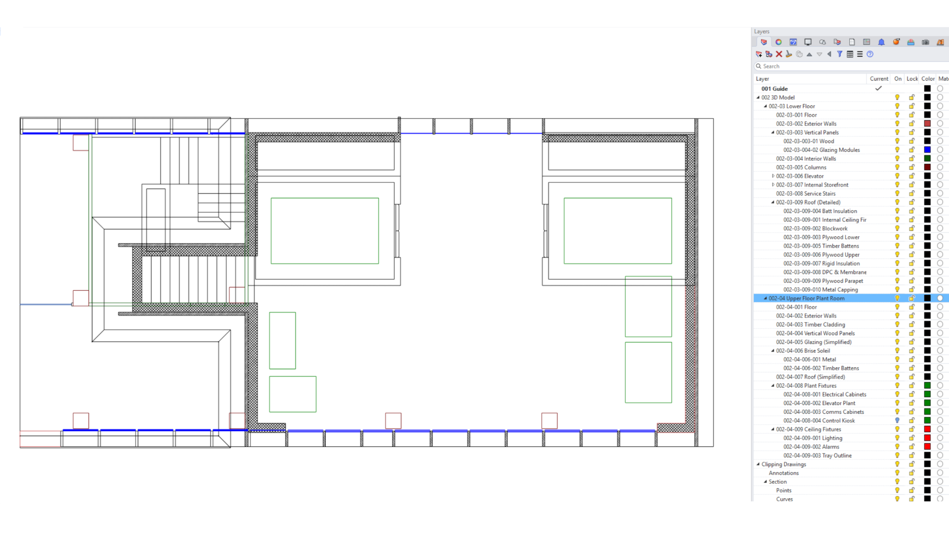
Placement point, place it next to theHorizontal_00drawing. Notice that no new layers are created. - It’s often useful to overlay horizontal sections so you can compare floor details over one another. Run AlignClippingDrawings
. At the
Select source drawingprompt, pick theHorizontal_012D Drawing; at theSelect target drawings to align with sourceprompt, pick theHorizontal_002D Drawing and press . The drawings are now aligned.
Control Drawing Properties
Clipping Drawing options are set when you create the ClippingDrawings
, but every option can be changed afterward. Double-click a 2D Drawing (or run  EditClippingDrawings
) to edit its properties.
EditClippingDrawings
) to edit its properties.
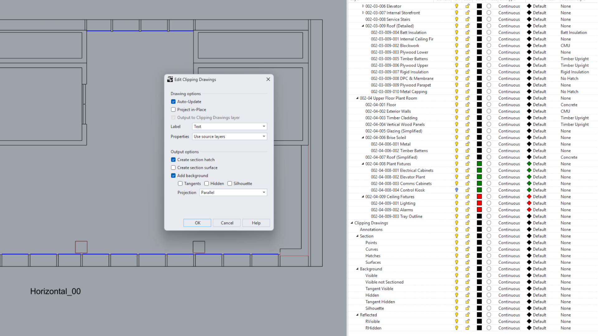
Drawing options
- Auto-Update: updates the 2D Drawing in Model Space and Layout Space whenever the Clipping Plane moves, or geometry in the selection changes. This can slow down performance on large models. If unchecked, run UpdateClippingDrawings
to refresh the drawing. Per-layer changes, such as a Section Style, always need an update this way, but clipped Model Space views (for example, a clipped Perspective viewport) always update immediately regardless.
- Project in Place: aligns the 2D Drawing with the Clipping Plane. Useful together with Create Section Surface.
- Output to Clipping Drawings layer: when Yes, every 2D section is placed on one shared set of nested layers named
Clipping Drawings. When No, each 2D section gets its own set of nested layers (Section_00,Section_01, and so on), which makes it easier to control visibility and line weight per drawing. - Label: choose Text (uses the current Text Style and Annotation scale), Dot, or None.
- Properties:
- By Output Layers: Display Color, Linetype, Print Color, and Print Width are controlled by the output layers described above.
- From Input Objects: those properties come from the source Model layers instead; the output layers above still control visibility.
- Use Source Layers: creates no new layers at all. Object properties are controlled entirely by the Model layers.
Output options
- Create Section Hatch: creates hatches controlled by each object’s Section Style. Section Style hatches always show in clipped Model Space views regardless of this setting.
- Create Section Surface: caps any open boundary created by the section with a physical surface; useful together with Project in Place for visualization.
- Add Background: shows detail behind the section slice, rather than just the cut itself.
- Tangents: shows the start and end of, for example, a filleted corner.
- Hidden: shows detail hidden behind the section.
- Silhouette: adds a thicker line around the outer perimeter of the 2D Drawing.
- Projection: choose Parallel, Perspective, Reflected, or Parallel and Reflected.
Because Clipping Drawings are block instances, all of this can be changed after the drawing is created. For example, start with Use Source Layers early in design, then switch to By Output Layers once the drawing set needs to become more formal documentation.