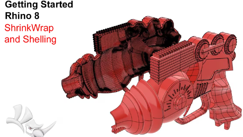
![]() ShrinkWrap
lets you create a wrapped mesh from mesh, NURBS geometry, SubD, and Point Clouds.
To prepare a file for 3D printing, you should have a single closed mesh. ShrinkWrap generates a closed mesh independent of the amount and type of geometry it is given. In this tutorial, we will see how ShrinkWrap works and how it can significantly reduce the time to prepare models for 3D printing.
ShrinkWrap
lets you create a wrapped mesh from mesh, NURBS geometry, SubD, and Point Clouds.
To prepare a file for 3D printing, you should have a single closed mesh. ShrinkWrap generates a closed mesh independent of the amount and type of geometry it is given. In this tutorial, we will see how ShrinkWrap works and how it can significantly reduce the time to prepare models for 3D printing.
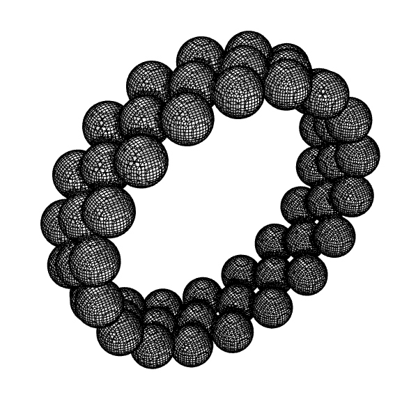
Example 1 - A ring made of spheres
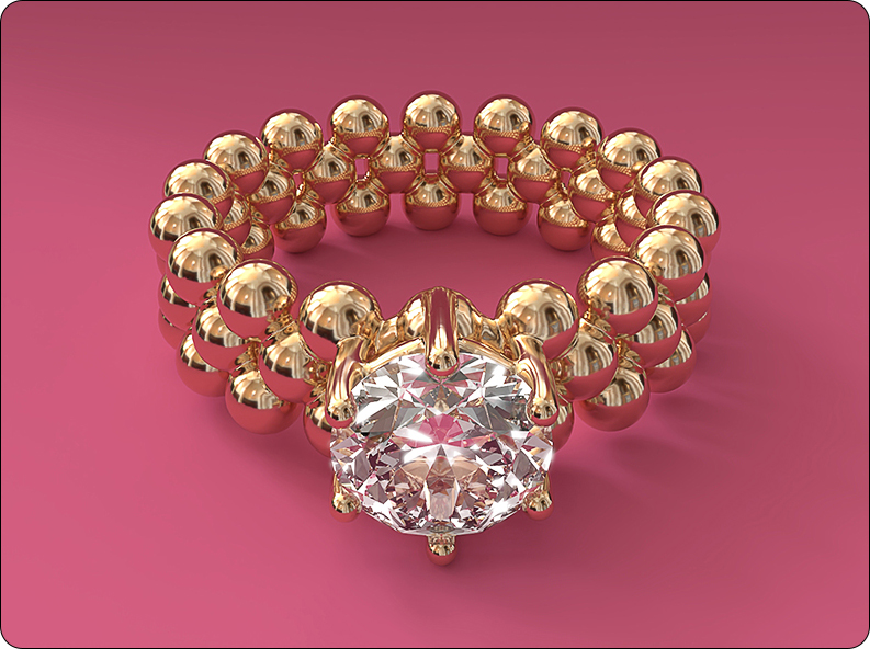
Download and open the 01-spheres-ring.3dm
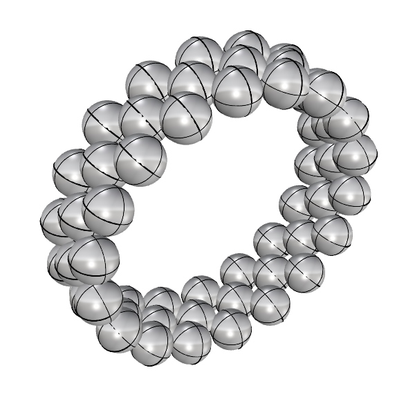
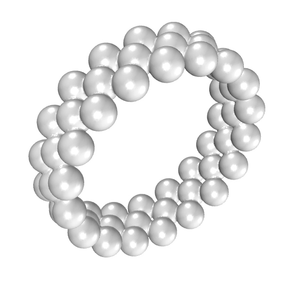
Note that the file consists of multiple spheres that are not connected. To prepare the design as a single mesh for printing, start
![]() ShrinkWrap
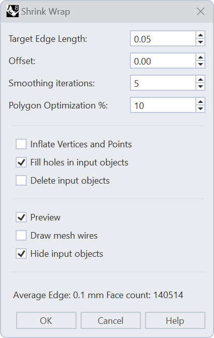
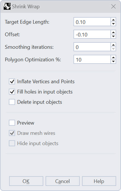
and select the 54 spheres. This will show the following dialog:
ShrinkWrap
and select the 54 spheres. This will show the following dialog:
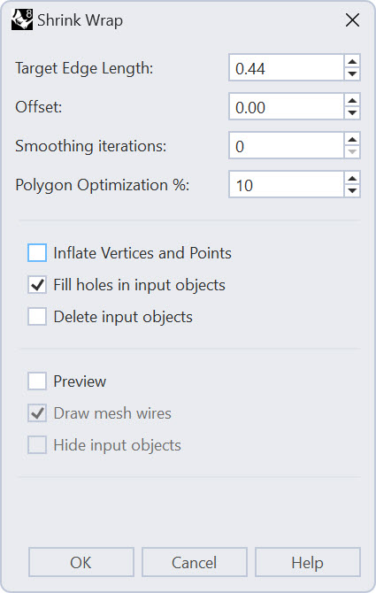
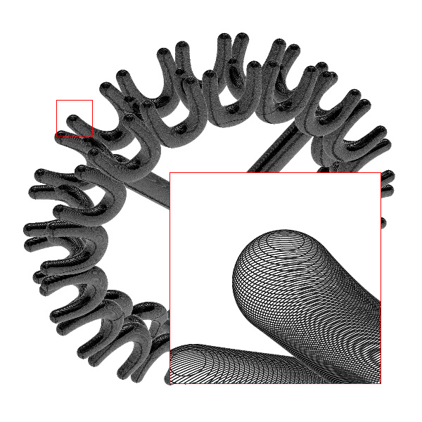
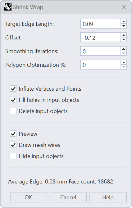
The most important setting is the Target Edge Length. This determines how detailed the mesh that is wrapped around your objects will be. ShrinkWrap will make an estimate based on the model size so that your first preview will give a reasonable result, but most likely, this value needs to be smaller to get an accurate enough wrap around the objects.
Check the options Preview and Hide input objects. Note that the mesh is quite coarse:
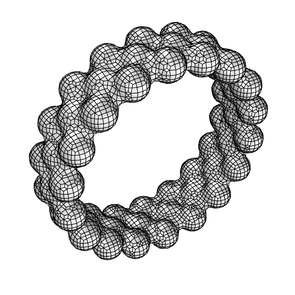
To get a better mesh, lower the target edge length to 0.1. Notice how the preview updates to a higher-density mesh that more closely follows the base objects:
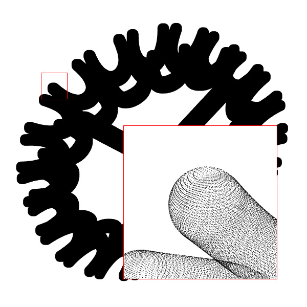
Hiding the mesh edges better shows what the object looks like. Do this by unchecking the option Draw mesh wires.
You can see that the resulting mesh still needs some refinement, and it might be desirable for post-processing to slightly smooth out the concave edges. Achieve this with the Smoothing iterations setting. Higher values will smooth the shape more. Convex sharp corners will be shaved off, and concave corners will be filled up. In the image below, smoothing is animated between 0 and 100 steps.

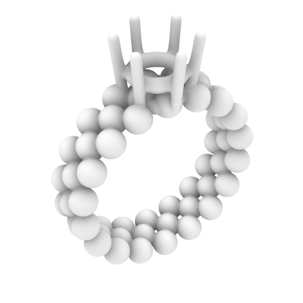
You are not limited to using NURBS objects for ShrinkWrap. We will now add a prong to the output and tune the units and smoothing for the final result.
Turn on the layer Prong. This is a SubD object. Select both the spheres and the prong and rerun
![]() ShrinkWrap
, this time with Target Edge Length of 0.05 and 5 Smoothing iterations :
ShrinkWrap
, this time with Target Edge Length of 0.05 and 5 Smoothing iterations :
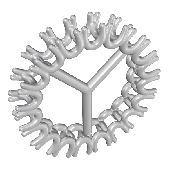
The result is a closed mesh that is ready to make a wax 3d print for lost wax casting.
Example 2 - Reverse engineering SLC
Download, unzip and open ring_slc.zip
If you inspect the file closely, you will see the file is made up of multiple slices made from a mesh. This means these curves are all polylines. To shrinkwrap these curves, we first extract the curves’ points into a Point Cloud.
Without the curves selected, run the command
![]() ExtractPt
and set the Command Line option Output to PointCloud. Now select the curves and press
to end the command.
ExtractPt
and set the Command Line option Output to PointCloud. Now select the curves and press
to end the command.
Select the Point Cloud created above and run
![]() ShrinkWrap
with these settings:
ShrinkWrap
with these settings:
Notice that the option Inflate Vertices and Points is automatically checked. This basically adds volume to each point. It also means that the size of the object we wrap will increase by the chosen Target Edge Length. To compensate for this growth, we can use a negative Offset.
The result is a closed mesh ready for 3D printing:
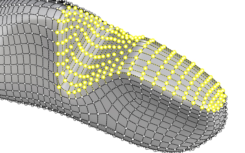
Example 3 - Wrap an incomplete scan
In this example, we explain how to create a usable closed shape, starting with a scan that has missing data.
Download and open shoelast.3dm
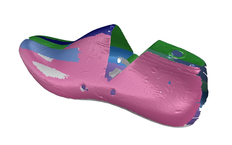
To make a closed mesh, ShrinkWrap can close holes, but there are limits to their size. The better we prepare the input, the finer we can set the Target Edge Length.
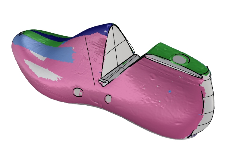
Close holes roughly by adding SubD patches. The tool to create these patches (
![]() 3DFace
) is in the left sidebar when the SubD tab is open. Turn on Vertex Osnap. Start making patches by snapping to the mesh and then sculpting and refining with point editing. Start with the largest holes, and check in between by shrinkwrapping the scans and SubD patches.
3DFace
) is in the left sidebar when the SubD tab is open. Turn on Vertex Osnap. Start making patches by snapping to the mesh and then sculpting and refining with point editing. Start with the largest holes, and check in between by shrinkwrapping the scans and SubD patches.
Once all holes are roughly closed,
![]() ShrinkWrap
with these settings:
ShrinkWrap
with these settings:
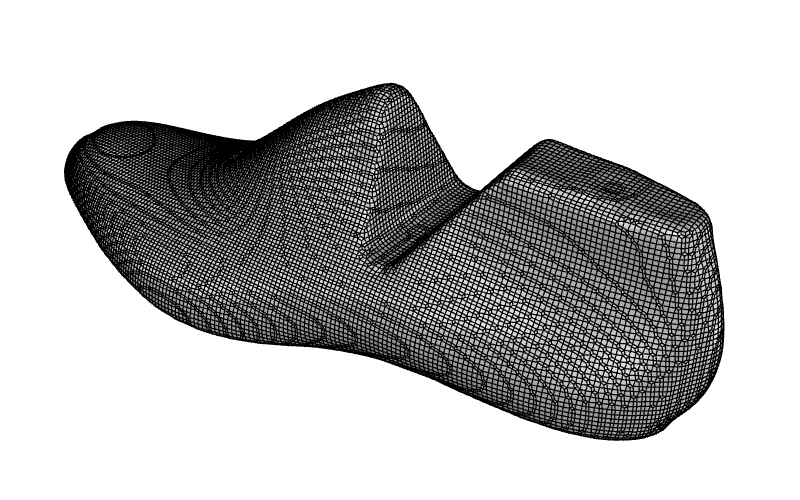
We can further refine the shape by using the shrinkwrapped result as a basis for
![]() Quadremesh
.
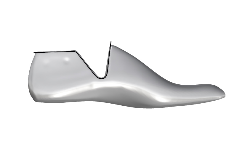
Before running Quadremesh however, we want to make a guide curve that we can use in Quadremesh to create an edge loop. In
view draw a curve that follows the last shape as indicated. Make sure the curve slightly intersects the mesh (e.g., is not above the mesh).
Quadremesh
.
Before running Quadremesh however, we want to make a guide curve that we can use in Quadremesh to create an edge loop. In
view draw a curve that follows the last shape as indicated. Make sure the curve slightly intersects the mesh (e.g., is not above the mesh).
Use
![]() ExtrudeCrv
to extrude this curve in both directions so that it fully intersects the mesh. Then, run
ExtrudeCrv
to extrude this curve in both directions so that it fully intersects the mesh. Then, run
![]() MeshIntersect
to intersect the result with the mesh.
MeshIntersect
to intersect the result with the mesh.
The result is a jagged degree 1 curve. Run
![]() Rebuild
, enable Delete Input and rebuild the curve to degree 3, 100 control points. Now run
Rebuild
, enable Delete Input and rebuild the curve to degree 3, 100 control points. Now run
![]() Fair
with Tolerance set to 100 to smooth the curve:
Fair
with Tolerance set to 100 to smooth the curve:
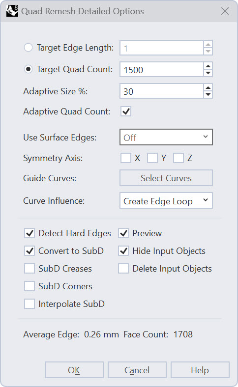
Start
![]() Quadremesh
and in the dialog, click the Select Curves button to select the faired curve. Change the Curve Influence to Create Edge Loop. Check Convert to SubD.
Quadremesh
and in the dialog, click the Select Curves button to select the faired curve. Change the Curve Influence to Create Edge Loop. Check Convert to SubD.
We will now refine the shape of the SubD in two ways. Hold (on Mac ) and double-click the edge loop that is nearest to the curve:
With these edges selected, run
![]() SubDCrease
and set the weight to 100 for the whole loop.
SubDCrease
and set the weight to 100 for the whole loop.
The next step is to flatten the area closest to the surface we created to intersect with the shrinkwrapped result. Turn on the points of the SubD (
![]() PointsOn
/ F10) and in
view, use
PointsOn
/ F10) and in
view, use
![]() Lasso
to select the points indicated:
Lasso
to select the points indicated:
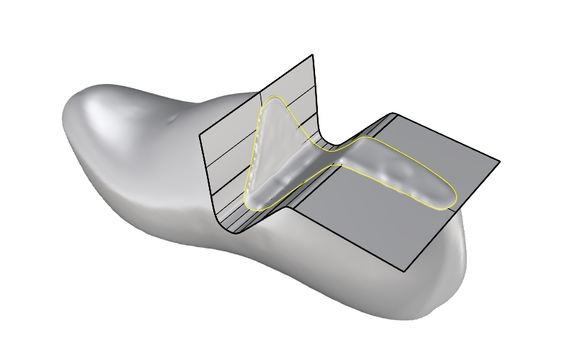
Turn on the guidesurface layer, and with the points still selected,
![]() Pull
the points to the guide surface.
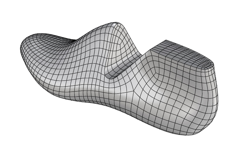
With a bit of point editing, we can further refine the shape to this result:
Pull
the points to the guide surface.
With a bit of point editing, we can further refine the shape to this result:
Other Tutorials
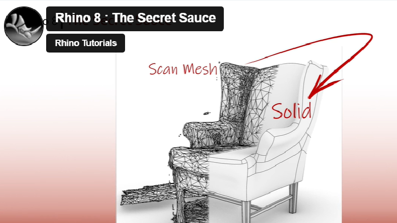
From Mesh to NURBS
Learn how to 'reverse engineer' a low poly 3D scan into a smooth, closed solid.
How to Shell
Learn how to create a shelled part in both the mesh and the NURBS solid using ShrinkWrap.
