Rhino 8 introduces tapers, cap styles and new width properties, along with the traditional line style settings. In this guide, you will learn how to combine these features to embellish and communicate your designs.
Pick one.
Enhanced Linetypes
Linetypes are curve styles with pattern, width, and taper properties. In previous versions of Rhino, linetypes were very limited: only dashes and dots on curves. Linetypes are now more beautiful and powerful than ever. Now you can add customized Linetypes to surfaces, solids, etc, allowing you to communicate design intent or artistic flair.
Unlike using traditional Rhino linetype patterns and simple print widths, the Enhanced Linetypes can be:
- Applied to more than curves, and support surfaces, polysurfaces, subds, dimensions, and more.
- Stylized curves with both width and taper.
- Fine tuned with line end and join style.
In this tutorial, you will assign the custom linetypes to layers that contain curves. It recommended to return the display modes to default settings to allow the new custom linetypes to display. It is also necessary to choose the option to print custom linetypes when printing. In this tutorial will give you a overview of this process.
In this tutorial, you will:
- Create enhanced linetypes
- Assign the custom linetypes to layers that contain curves, polysurfaces and Sub-D surfaces.
- Preview the assigned linetype
- Print the linetypes to PDF
Preparing Rhino for Enhanced Linetypes
It is sometimes necessary to return the display modes to default settings to allow the new custom linetypes to display. It is also necessary to choose the option to print custom linetypes when printing. In this tutorial will get an you a overview of this process.
Verify these Rhino settings
- Print Preview needs to be of turned off. (PrintDisplay command)
- Enhanced Linetypes also do not display if the Display Mode has Curve Width set to Pixels. Reset your Display Mode to Default settings.
Returning your Display Modes to default
-
Type the Options command.
-
Navigate to View and Display modes.
-
Pick Wireframe and select: Restore Defaults
-
Pick Render and select: Restore Defaults.
-
Pick OK to exit Options.
-
Close and reopen Rhino.
Creating Enhanced Linetypes
You will create enhanced linetypes in the Linetypes panel.
-
Download the current Rhino Eval if you don’t yet have Rhino installed.
-
Download the model for this tutorial. Using-custom-linetypes.3dm model.
-
Open the file in Rhino.
-
At the command prompt, type the command Linetypes. The Linetypes panel will open.
-
In the Linetypes panel, highlight Continuous, and right-click to pop up the context menu.
-
From the menu, pick Copy. linetype Continuous 01 is created.
-
Repeat the Copy and Continuous 02 is created.
-
Repeat the Copy and Continuous 03 is created.
-
Repeat the Copy and Continuous 04 is created.
Editing the Linetypes for Taper
-
Scroll and highlight the new linetype Continuous 01.
-
In the lower part of the panel, make these changes to Continuous 01:
- Name: Custom Taper Thick
- Width: 1
- Width Unit: Pixels
- Tapered: Enable with check
- Taper Position: 0.20
- Taper Width: 6
- Taper End Width: 1
-
Scroll and highlight the new linetype Continuous 02.
-
In the lower part of the panel, make these changes to Continuous 02:
- Name: Custom Taper Thin
- Width: 1
- Width Unit: Pixels
- Tapered: Enable with check
- Taper Position: 0.50
- Taper Width: 4
- Taper End Width: .5
-
Scroll and highlight the new linetype Continuous 03.
- Name: Custom Continuous
- Segments Unit: Millimeters
- Width: 3
- Width Unit: Pixels
-
Scroll and highlight the new linetype Continuous 04.
- Name: Custom Dashed
- Segment Unit: Inches
- Segments: 5.00, 2.00
- Width: 2
- Width Unit: Pixels
Now the new linetypes Custom Taper Thick, Custom Taper Thin, Custom Continuous and Custom Dashed are ready to assign to layers or objects.
Assigning the Linetypes to Curves, Surfaces and SubD Geometry
Assigning Linetypes to Curves
-
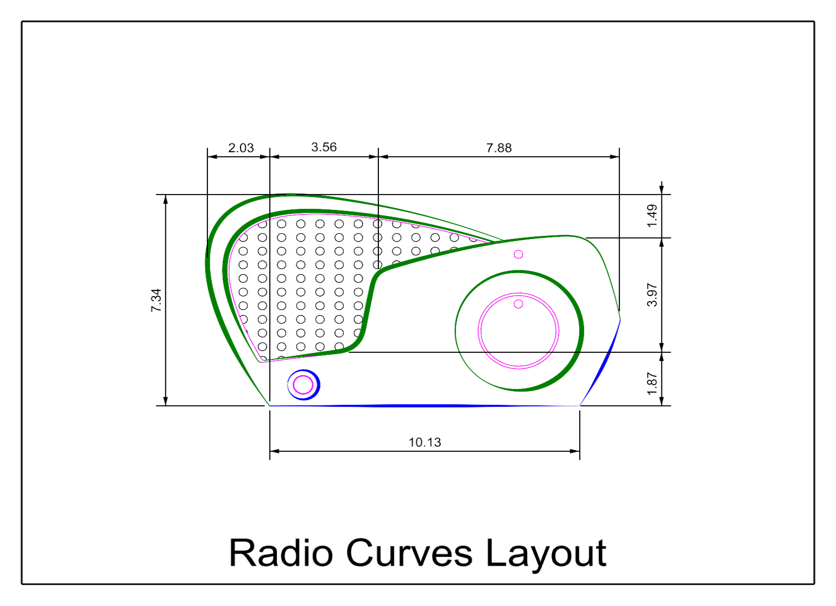
Double-click viewport title Radio Curves.
-
Type the Layer command, to open or set the Layers panel current.
-
Navigate to 1 RadioCurves\Taper Thick layer
- In the Linetype column, set the linetype to Custom Taper Thick.
- Navigate to 1 Radio Curves\Taper Thin layer, and set the linetype to Custom Taper Thin.
- Navigate to 1 RadioCurves\Custom Continuous, and set the linetype to Custom Continuous.
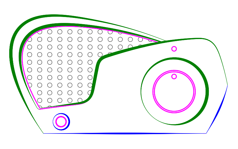
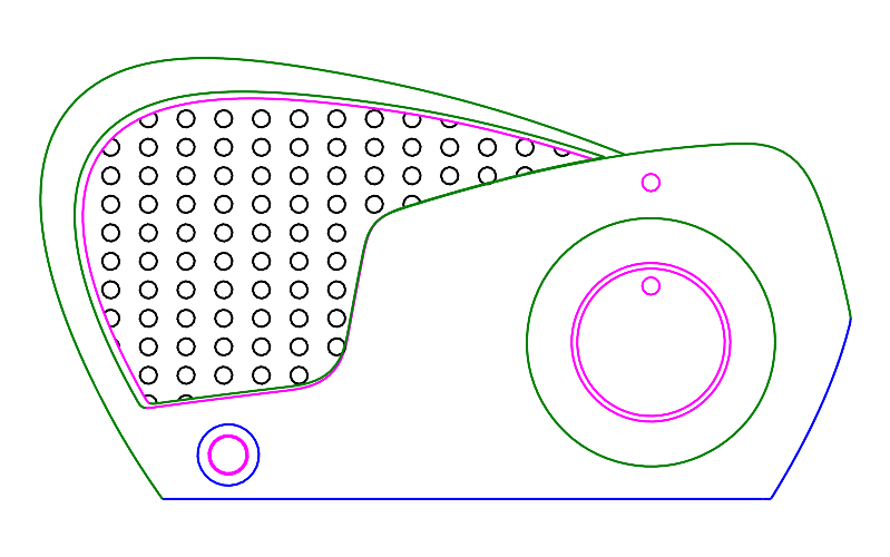
Curves with Custom Linetypes
Assigning Linetypes to Polysurfaces
-
Double-click viewport title Radio Curves to return to 4 viewport display.
-
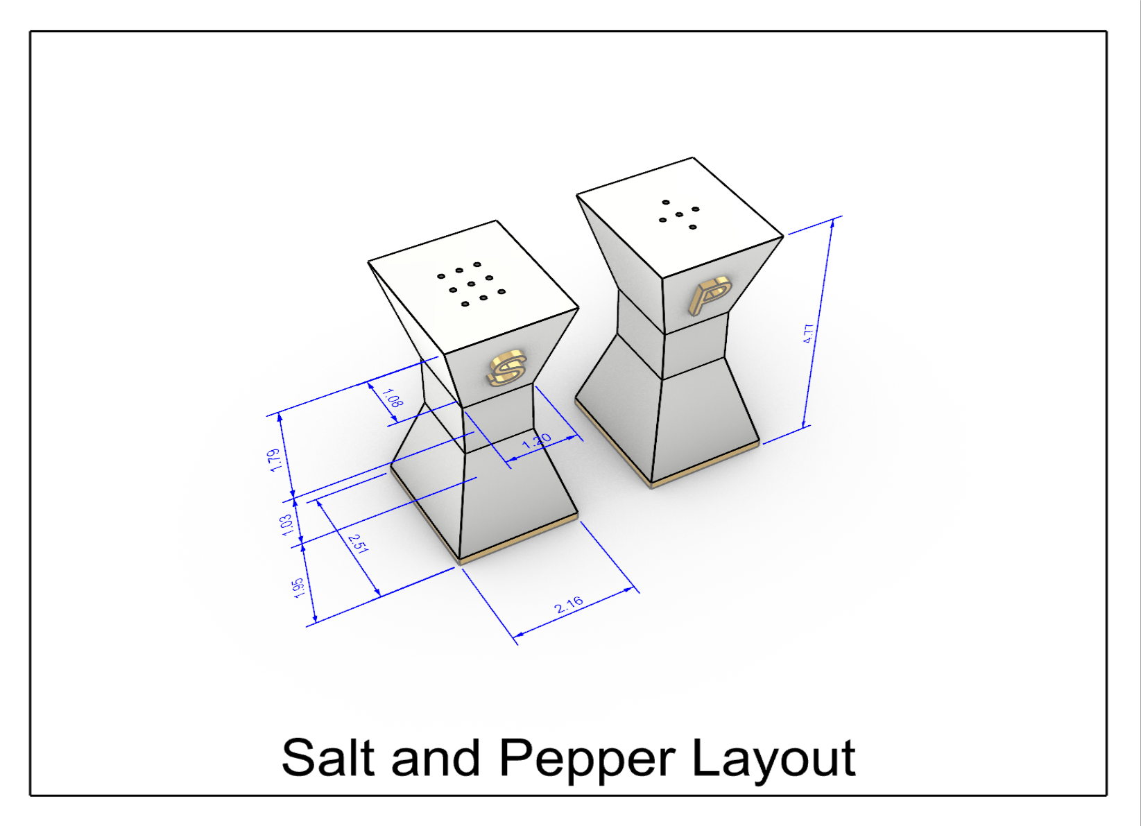
Double-click viewport title Salt and Pepper.
-
In the Layers panel, navigate to 2 Salt and Pepper layer.
- In the Linetype column, set the linetype to Custom Continuous.
- Pick OK.
-
Type the DisplayProperties command. Verify the Display mode is set to Rendered.
-
Under General Settings, check Surface Edges.
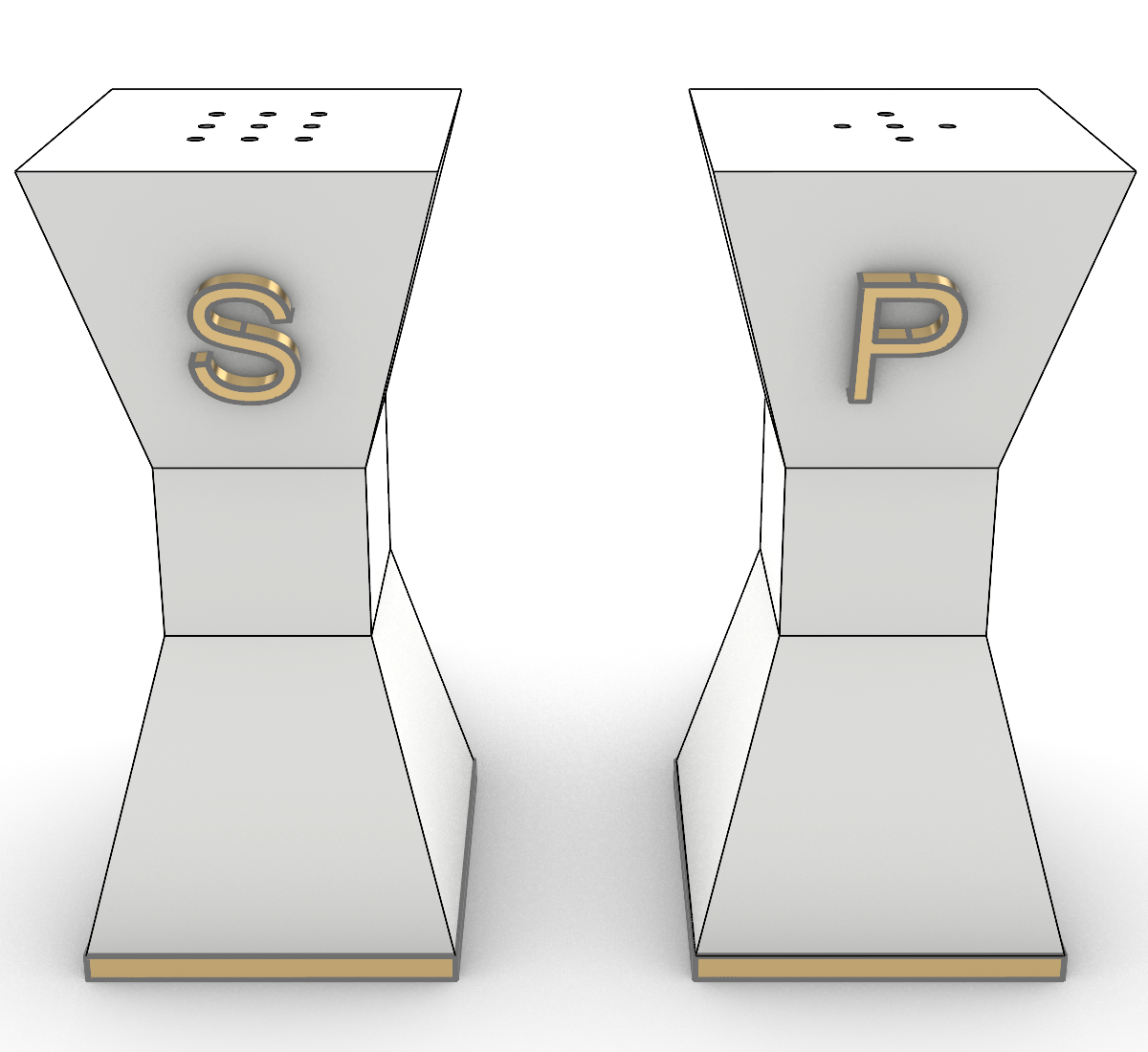
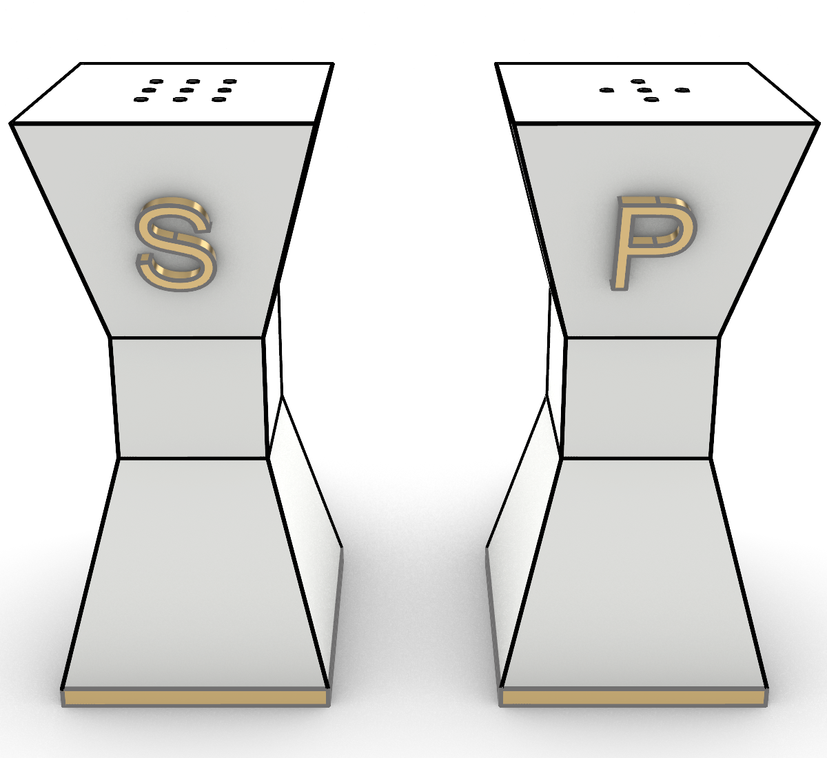
Surfaces with Custom Linetypes
Assigning Linetypes to SubD Surfaces
-
Double-click viewport title Salt and Pepper to return to 4 viewport display
-
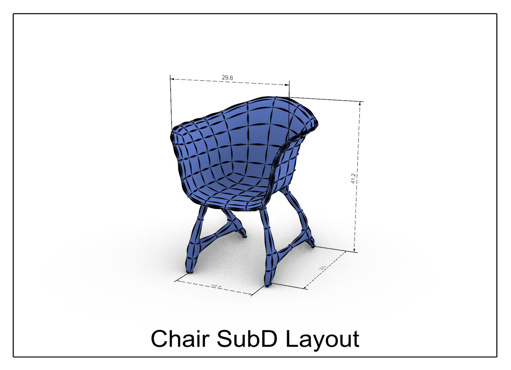
Double-click viewport title SubD Chair.
-
Type the Layer command, navigate to 3 Chair\Chair Subd layer.
- In the Linetype column, set the linetype to Custom Taper Thin. Pick OK.
- Then in the Linetype column, set the linetype to Custom Dashed. Pick OK.
- Also navigate to layers 1 Radio\Radio Dims and 2 Salt and Pepper\SP Dims layer.
- Turn both layers On.
- Then in the Linetype column, set the linetype to Custom Dashed. Pick OK.
- Navigate to 3 Chair\Chair Dims layer. Turn it On.
-
Type DisplayProperties. Verify the Display mode is set to Rendered.
-
Under General Settings, check SubD Wires.
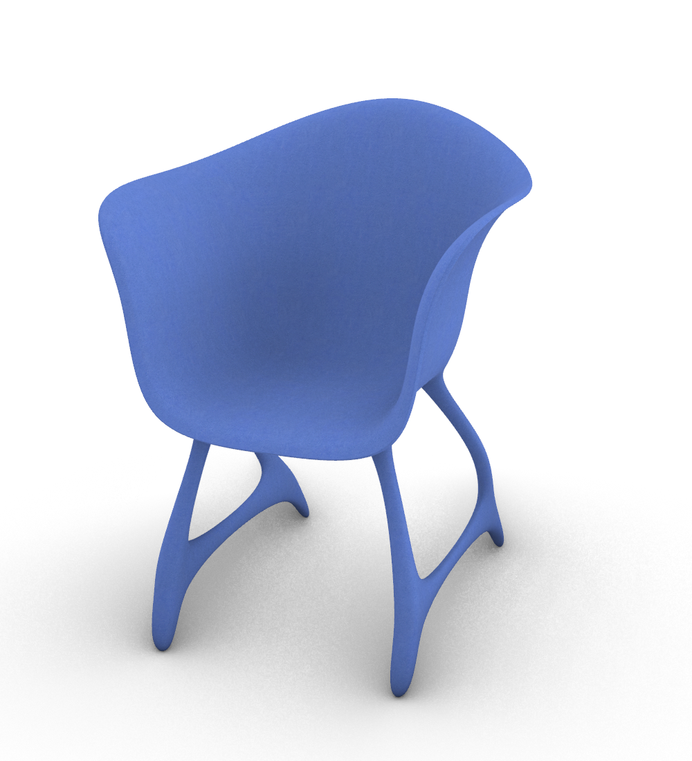
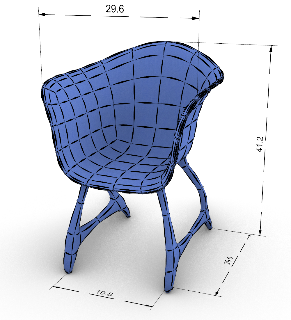
SubD with Custom Linetypes
Printing with Enhanced Linetypes
-
Double-click viewport title Subd Chair Perspective to return to 4 viewport display.
-
Pick the tab below the viewport area to active the Radio Curves Layout tab. Then click the other tabs below the viewport area to active the Salt & Pepper Layoout tab and Chair SubD Layouts tab, and then back to Radio Curves Layout tab.
-
Type the Print command. Select Rhino PDF printer.
- Under Size, check box to Use Layout Page Size.
- Set Output type to Raster.
- Set Output Color to Display Color.
- Under View and Output Scale, select Print Multiple Layouts.
- Under Scale pick 1:1 or Scale to Fit.
-
Preview the sheets by picking on each of the layouts under the column heading Select a layout to preview. Also select and deselect all by picking on the column heading Print.
-
At the bottom of the Print dialog, check option Open after saving. When printing is complete, your PDF will open in your system’s designated PDF reader.
-
Now pick the Print button. Specify the name and location for your PDF.
-
Download the PDF Using-custom-linetypes.pdf or the completed model using-custom-linetypes-done.3dm