![]()
Surface Tools > Rebuild Surface
Curve Tools > Rebuild
![]()
Edit > Rebuild
Reconstructs selected curves or surfaces to a specified degree specified and number of control points.
Steps:
Select the curves or surfaces.
To rebuild curves
Click Preview to see what the rebuilt curves will look like.
When you are satisfied with the results, click OK.
Notes
Turn on control points and curvature graph to see the details of the curve structure.
A group of curves will be rebuilt with curves of a specified degree and specified number of control points. The knots of the resulting curve more evenly spaced. To rebuild a curve with uneven knot spacing but a more accurate fit, use the FitCrv command.
Options
Point Count
Sets the number of control points used to rebuild the selected curves. The number of control points in the original curve is in parentheses.
Degree
Sets the degree for the new curves or surface. You can create curves of degree 1 through 11.
Create new curve on current layer
Creates the new curves on the current layer. Clear this checkbox to place the new curves on the layer of the original curves.
To rebuild surfaces
Click Preview to see what the rebuilt surfaces will look like.
When you are satisfied with the results, click OK.
Options
Point Count
Sets the number of points in the u- an v-directions.
Degree
Sets the degree for the new surface. You can create surfaces of degree 1 through 11.
Current Layer
Creates the new surfaces on the current layer. Clear this checkbox to place the new surfaces on the layer of the original surfaces.
Retrim
Trims the rebuilt surface with the original trimming curves.
Maximum deviation
Samples the original surface at knots and halfway between the knots. It then pulls the sample points to the rebuilt surface and calculates the deviation.
Calculate
The calculation tests how far away the new surface is at knot line intersections and half-way between knot lines. Conducts tests at knot line intersections and halfway between knot lines.
The display color indicates how far away the new surface is from the original. Points are green if the surface is within absolute tolerance, yellow if it is between tolerance and 10 times tolerance, and red if it is farther away than that.
The lines are 10 times longer than the measured deviation in the direction of the deviation.
The hyphenated version adds an additional command line option.
SelectMasterCurve
A master curve dictates the structure of all of the output curves. This is useful when matching a set of curves to one for lofting, sweeping, etc.
|
Surface Tools > Rebuild Surface Curve Tools > Rebuild
Edit > Rebuild |
Allows interactive modification of the curves to more closely match the original by spacing the control points non-uniformly.
Steps:
Select the curves.
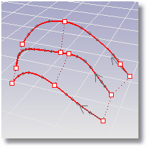
Drag the points on the curves.
Click the direction arrows to reverse the curve direction.
Options
RequestedTolerance
Specifies the maximum distance the rebuilt curves can deviate from the originals. If you do not provide enough control points, the rebuilt curves may deviate more than RequestedTolerance from the originals.
The maximum deviation from the original curves is reported at the command line and marked with a point on the curve.
MaxPointCount
Specifies the maximum number of control points per curve used to rebuild.
Quarters
Displays two more controls along each curve to influence how the RebuildCrvNonUniform command distributes control points. The controls at the end of the curves can be used to shorten the resulting curves.
ResetPoints
Resets the editing points to their original locations.
|
Curve Tools > Rebuild Curves NonUniform
None |
Restores original 3-D surface edges that have been forced away from the surface through editing.
Steps:
Select an object.
This command is useful for restoring original 3-D edges of surfaces after exploding a polysurface into separate surfaces.
To see what it does:
Draw two planes several units apart.
Force Rhino to join the surfaces with the JoinEdge command.
Explode the object and then use the RebuildEdges command to restore the edges.

Joined and exploded polysurface. Edges are pulled away from the surface.
Options
Tolerance
Overrides the system tolerance setting.
|
Edge Tools > Rebuild Edges
Analyze > Edge Tools > Rebuild Edges |
Changes a curve or surface so it is knot-vector uniform.
Guarantees that every control point affects the surface exactly the same way, no matter how much the surface is edited.
Steps:
Select curves or surfaces.
The MakeUniform command makes the object knot vector uniform without changing the control point locations. This will change the object shape slightly.
|
Curve Tools > Make Uniform
None |
Reduces the number of curve control points while maintaining the curve's same general shape.
Steps:
Select curves.
Type a new tolerance value or press Enter.
You can also pick two points to set the tolerance.
Type 0 (zero) to use the current absolute tolerance.
Notes
Use the FitCrv command for replacing curves with too many control points.
When the input to the FitCrv command is a polyline, the FitCrv command treats the polyline vertices as a list of points, and it tries to compute a curve that goes near the points but has a reasonable number of control points. The FitCrv command is meant for polylines with many closely spaced points.
When the input to the FitCrv command is a control points wiggly curve with many control points, the FitCrv command tries to compute a curve that has the same general shape but fewer control points.
Options
Degree
You can set the degree of the curve up to 11.
When drawing a high-degree curve, the output curve will not be the degree you request unless there is at least one more control point than the degree.
|
Curve Tools > Refit Curve
Curve > Curve Edit Tools > Refit to Tolerance |
Replaces each curve segment that has the geometry of a line or an arc with a true line or arc. The command also combines consecutive co-linear and co-circular segments.
Steps:
Select curves.
Notes
NURBS curves are broken apart at fully-multiple knots.
Tangent (G1) joins are tuned up to meet tangent with machine precision.
|
Curve Tools > Simplify Lines and Arcs
Curve > Curve Edit Tools > Simplify Lines and Arcs |
Removes large curvature variations in a curve while limiting the geometry changes to the specified tolerance.
Steps:
Notes
The Fair command works best on degree 3 curves.
Sometimes you must run the Fair command several times in order to remove curvature problems.
You can use the CurvatureGraph command to view the curvature hair while fairing.
|
Curve Tools > Fair Curve
Curve > Curve Edit Tools > Fair |

Averages the positions of curve and surface control points and mesh vertices in a specified region.
The Smooth command evens out the spacing of selected control points in small increments. This command is useful for removing unwanted detail, and for removing loops in curves and surfaces.
On mesh objects use the Weld command before smoothing in order to prevent the mesh from pulling apart.
Steps:
Select curves, meshes, or surfaces to smooth and press Enter.
The selected entities will appear to melt, losing detail due to the averaging of the positions of the control points.
To smooth part of a curve or surface
Select a curve or surface to smooth.
Use the PointsOn command to turn on the object's control points.
Select the control points in the region of the curve or surface to smooth.
Start the Smooth command.
Click the checkboxes for the coordinate directions and adjust the Smooth factor.
Note: To set one check and clear the others, right-click the checkbox.
The selected control points will move slightly, smoothing the curve or surface.
Options
Smooth X/Smooth Y/Smooth Z
Smooths only in the specified x-, y-, or z-direction.
World coordinates/CPlane coordinates
Use world or construction plane coordinates to determine the direction.
Smooth factor
0 to 1
The curve control point toward the average.
Greater than 1
The curve control point moves past the average.
Negative
The curve control point moves away from the average (roughing).
|
Transform > Smooth Geometry Fix > Smooth
Transform > Smooth |
Reduces the number of surface control points while maintaining the surface's same general shape.
Steps:
Select surfaces.
Type a new tolerance value or press Enter to accept the default.
Type 0 (zero) to use the current absolute tolerance.
Notes
Use the FitSrf command for replacing surfaces with too many control points.
When the input to the FitSrf command is a wiggly surface with lots of control points, the FitSrf command tries to compute a surface that has the same general shape but fewer control points.
Options
ReTrim
Trims the new fit surface with the original trimming curves.
UDegree/VDegree
Sets the degree of the surface in the u -or v-direction.
|
Surface Tools > Refit surface to tolerance
Surface > Surface Edit Tools > Refit to Tolerance |
Changes the structure of a curve to polyline or arc segments.
Steps:
Select curves to convert.
Select options.
Options
Output
Arcs
Converts the curve to arc segments. Sections of curves that are nearly straight are converted to straight-line segments.
Lines
Converts the curve to polyline segments.
SimplifyInput
Yes
Combines co-linear line segments and co-circular arc segments.
Simplifying ensures that NURBS curves that consist of arc and line segments are split into proper arc and line segments making the conversion to arcs and lines more accurate.
Note: The simplification step is done using the absolute and angle tolerance, not the custom tolerance settings set in the command.
No
Sometimes simplifying can be too aggressive, converting normal NURBS curves into arcs or lines, especially if the curves are very small in relation to the absolute tolerance. In that case turning off simplifying may give a better and more accurate answer.
AngleTolerance
The maximum allowed deviation from the curve direction at the arc segment endpoints.
Set AngleTolerance to zero to turn off the mechanism that keeps the arc segments tangent to each other and close to being tangent to the input curve. The output will have kinks, but since it consists of arc segments, there will be fewer segments than if the Lines option was used. This is useful for approximating a curve with the smallest number of segments.
Tolerance
Overrides the system tolerance setting.
|
Curve Tools > Convert Curve to Polyline/Convert Curve to Arcs (Right click)
Curve > Convert |
Changes the structure of a NURBS curve or surface to a Bézier curve or surface.
Steps:
Select the objects.
Choose either to keep or to delete the input objects.
|
None
None |
Recalculates an object's parameter space to be roughly the same size as its 3-D geometry.
Steps:
Specify the new limits of the u and v domains for the surface.
You generally do not need to care much about surface parameterization, including the domain, unless you apply textures. Then you may need to change the domain so as to make the texture apply correctly to the surface.
Notes
The parameters values of the objects recalculate so that the parameter space of the objects is roughly the same size as the 3-D geometry of the objects.
Poorly parameterized objects may not intersect and trim properly when combined with other objects. "Poorly parameterized" means the curve's domain or the surface's u- or v- spaces are tiny or huge compared to the size of the object.
|
None
None |
Reports the u- and v-coordinates of a selected location on a surface.
Steps:
Options
CreatePoint
If Yes, creates a point object on the surface.
Note: When you pick a polysurface, Rhino calculates the result for the component surface at the location you pick. If the surface is trimmed, Rhino uses the untrimmed surface.
|
Analyze > Evaluate Point uv Coordinates (Right click) Surface Analysis > UV Coordinates of a Point (Right click)
Analyze > Surface > UV Coordinates of a Point |
Creates point objects by entering surface u- and v-coordinates.
Steps:
Select a surface.
Type a u-value within the displayed domain.
Type a v-value within the displayed domain.
Press Enter to end the command.
Options
CreatePoint
If Yes, creates a point object on the surface.
Note: When you select a polysurface, Rhino calculates the result for the component surface at the select location. If the surface is trimmed, Rhino will use an untrimmed surface.
|
Surface Analysis > Point from UV Coordinates
Analyze > Surface > Point from UV Coordinates |
Evaluates and reports the domain of a curve or surface.
Steps:
Select a curve or surface.
The curve domain or the surface u and v domains display on the command line.
For a polysurface, the domain is calculated for the component surface.
|
Analyze > Domain (Right click)
None |