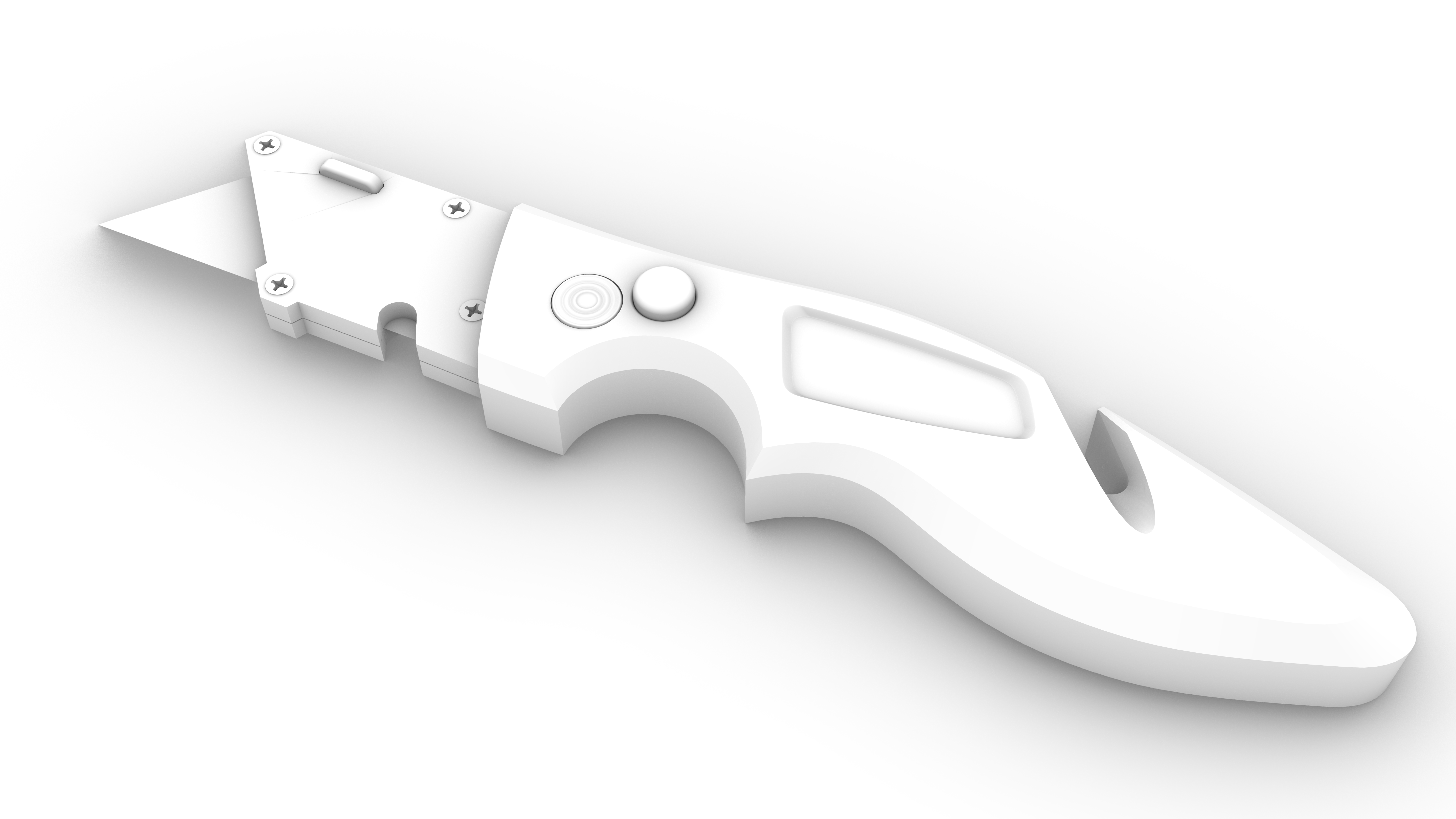
Rhino provides tools to create photo-realistic images of your 3D models or scene. You can set the scene environment, apply materials and control lighting. This process is called Rendering. In this chapter, we will browse through the different tools to help us achieve compelling visuals with Rhino.
The Rendering Process
The process to render consists of four basic steps:
- Assign materials.
- Set up the scene:
- Environment
- Skylight
- Ground Plane
- Add lights if necessary.
- Render.
There are several ways you can preview the scene rendered:
- Set the view to Rendered Mode .
- Set the view to Raytraced Mode .
- Run the
 Render
command.
Render
command.
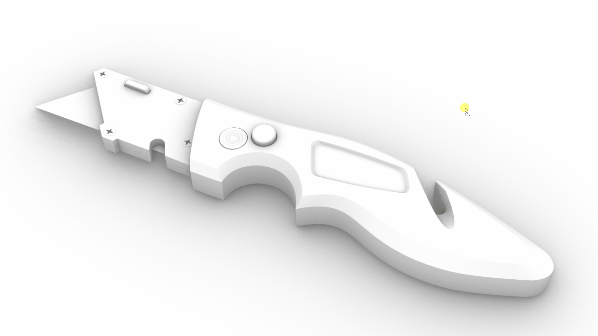
By default, objects are displayed in white, until you apply materials.
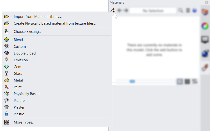
Materials
![]() Materials
specify the color, finish, transparency, texture and bump for use by the renderer. They can simulate real-world materials such as plastic, metal, glass, etc.
Materials
specify the color, finish, transparency, texture and bump for use by the renderer. They can simulate real-world materials such as plastic, metal, glass, etc.
Create or import materials in the
![]() Materials
panel, then assign materials to layers or objects. You can drag materials from the material library and drop them onto objects.
Materials
panel, then assign materials to layers or objects. You can drag materials from the material library and drop them onto objects.
Apply Materials by Object
In this exercise, we will learn to assign a material per object. Once the material is created, you can drag and drop it onto an object. You can also select an object and apply the material in the Materials page of the
![]() Properties
panel.
Properties
panel.
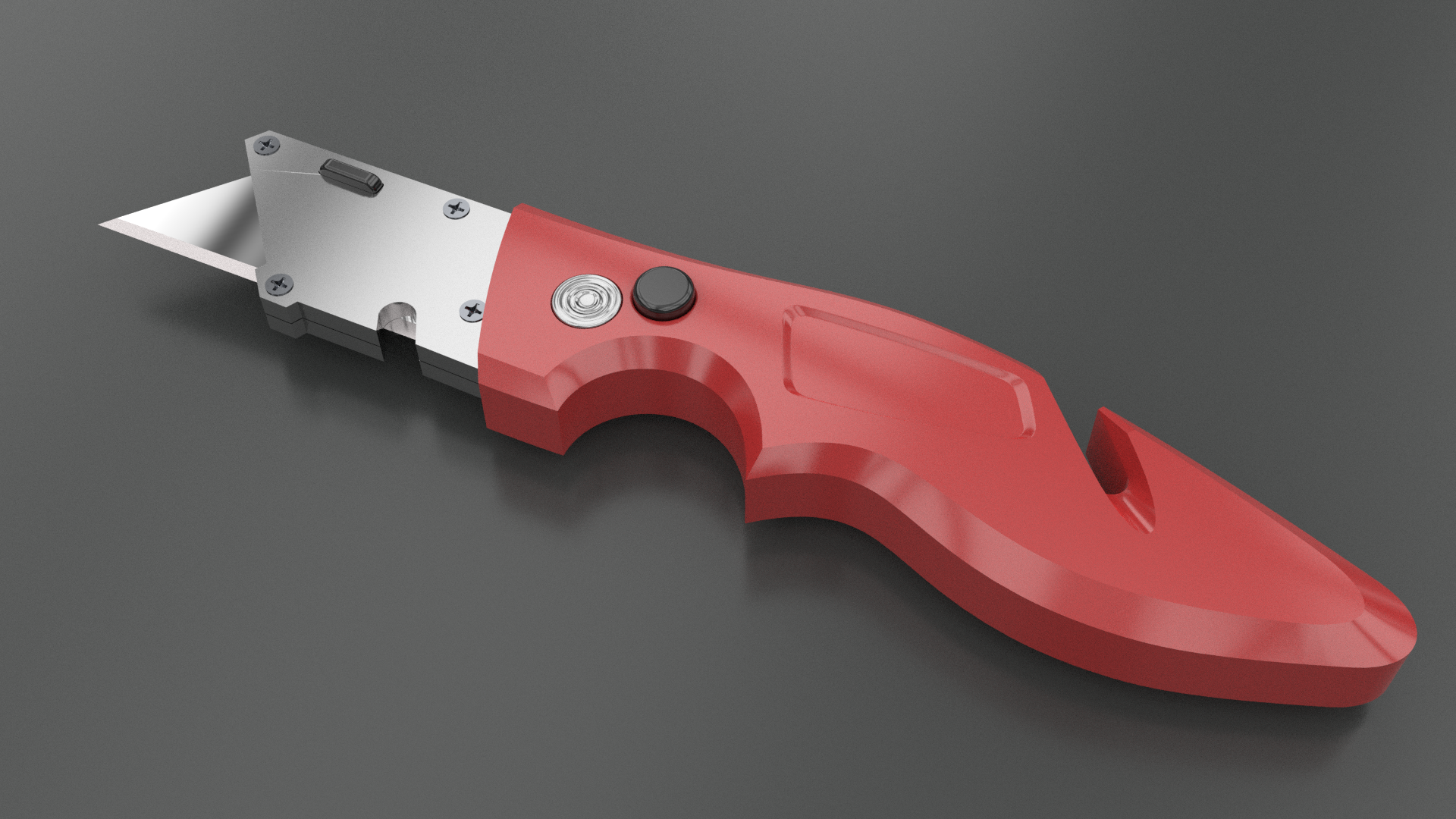
- Open Materials-Utility-Knife.3dm in Rhino .
- Set the view to Rendered Mode .
- Run the
 Materials
command to open the panel.
Materials
command to open the panel. - Click on the Add Material icon.
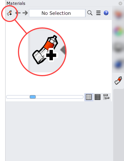
- Select Plastic from the list.
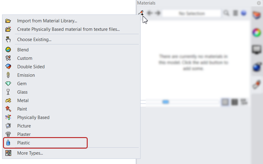
- The Plastic Template will appear in the
Materials
editor.
- Under Name and Type, change the name to Handle.
- Under Color, click to change the hue to a red tone (#B74242). The Plastic thumbnail preview will update.
- Drag the Plastic thumbnail from the
Materials
panel onto the handle.
- Under Plastic Material, lower the Reflectivity slider to 40%. Notice how the material becomes less reflective.
- Increase the Transparency slider to 100%.
- Change the view to Raytraced Mode to see a more accurate visual result.
- Try it on your own! Play around with other Plastic settings in the
Materials
panel. The handle will update in realtime.
Apply Materials by Layer
In this exercise, we will learn to assign a material per layer. This is useful when you need to apply the same material to multiple objects and they all lie in the same layer. We will access the material editor, directly from the
![]() Layer
panel.
Layer
panel.
- Continue working with the Materials-Utility-Knife.3dm downloaded above.
- Make sure the view is set to Rendered Mode .
- Go to the
 Layer
panel, located on the right side panel.
Layer
panel, located on the right side panel. - Turn off / on the Slider layer. You’ll notice it contains multiple objects controlled by the layer.
- On the Slider layer, click on the Material icon. This will open the
Materials
editor.
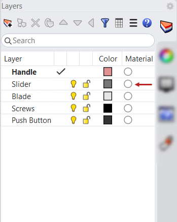
- Select the Default Material dropdown and then click on the + sign.
- Select Import from Material Library. This will open Rhino’s built-in Materials folder.
- Browse to the
Metal/Polishedfolder. - Select Polished Chrome.rmtl.
- Click OK to close the
Materials
editor.

- Try it on your own! Keep adding materials to the rest of the objects in the scene.
Scene
The scene usually refers to the visible background that surrounds the model:
- Environment (or back drop)
- Skylight
- Ground Plane
There are several ways to configure the scene in Rhino. Sometimes we want it as the visible background. Sometimes the
![]() Environments
will be used for lighting and reflection only and the
Environments
will be used for lighting and reflection only and the
![]() GroundPlane
will recieve shadows only, while being invisible.
GroundPlane
will recieve shadows only, while being invisible.
Environment & Skylight
In this exercise, we will play with the Background settings in the
![]() Rendering
panel. We will change the Background color and use different Environments to change the reflections and light intensity in the scene, controlled by the Skylight.
Rendering
panel. We will change the Background color and use different Environments to change the reflections and light intensity in the scene, controlled by the Skylight.
- Open Scene-Utility-Knife.3dm in Rhino .
- Set the view to Rendered Mode . You’ll notice the scene is white.
- Run the
 Rendering
command to open the panel.
Rendering
command to open the panel. - In the panel, under Background, select Gradient. You’ll notice the scene background changes from white to a greyscale gradient.
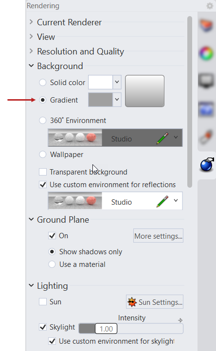
- Click on the bottom color swatch to change the hue to a sand color (#C2C1BF).
- In the
Rendering
panel, under Use custom environment for reflections, click the dropdown menu, then the + sign.
- Select Import from Environment library. This will open Rhino’s built-in Environment folder.
- Browse and select Dublin Studio environment. Press OK. Notice how the reflections change on the object. They inherit the Environment image’s light and dark spots.
- . In the Lighting section of the panel, increase the Skylight’s Intensity slider to 1.20.
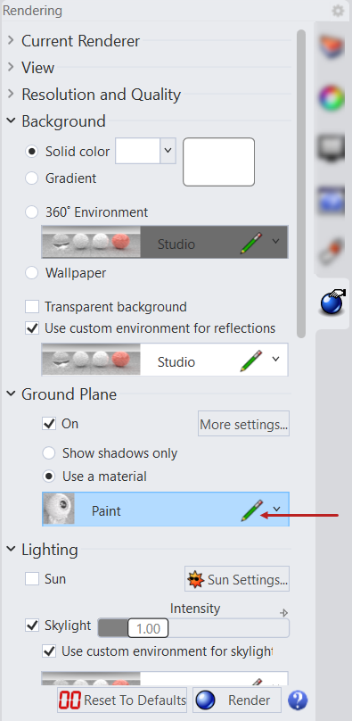
Ground Plane
By default, the
![]() GroundPlane
is invisible and set to recieve shadows only from the objects in the scene. In this exercise, we will add a material to the Ground Plane through the
GroundPlane
is invisible and set to recieve shadows only from the objects in the scene. In this exercise, we will add a material to the Ground Plane through the
![]() Rendering
panel.
Rendering
panel.
- Open Scene-Utility-Knife.3dm in Rhino .
- The view is set to Rendered Mode . You’ll notice the surrounding scene is white.
- Run the
Rendering
command to open the panel.
- In the panel, under Ground Plane, select Use a material. A dropdown menu appears.
- Click on the dropdown menu and select the + sign.
- Add a Paint Material from the list. The ground plane material is now set to a white plastic.
- Click on the Pencil icon by the Paint material. This will open the Material Editor. You might need to increase the size of the box to access its setting.
- Click on the Color box to change the swatch.
- Select a dark grey. Press OK.
- Back to the Material Editor, decrease the Gloss slider to 88%. Close the editor.
Lights
Lighting is one of the most relevant aspects of succeeding a render. In the previous exercises, lighting was managed through the Skylight. It is on by default in both
Rendered
and
Raytraced
display modes. You can control it through the
![]() Rendering
panel. It consists of a dome of invisible lights that surround the scene. It creates soft shadows and a well rounded lighting effect.
Rendering
panel. It consists of a dome of invisible lights that surround the scene. It creates soft shadows and a well rounded lighting effect.
There are times when we want more granular control over lighting. In this exercise, we will learn how to create
![]() Lights
in Rhino to bring out different aspects of our product, through lighting and reflection.
Lights
in Rhino to bring out different aspects of our product, through lighting and reflection.
- Open Lights-Utility-Knife.3dm in Rhino .
- Click in the view and press . This will activate the camera object in the Parallel views.
- Change the viewport to Rendered .
- Run the
 Lights
command to open the panel.
Lights
command to open the panel. - In the panel, click the Skylight light bulb to turn it off. The scene lighting and shadows become harsher.
- Run the
 RectangularLight
command.
RectangularLight
command. - In the Command Prompt , click on Target and snap somewhere between the blade and the handle.
- In the view, click the first point to define the height of the light.
- In the view, click the second and third points to define the length and the width of the light.
- In the
viewport, run the
 Mirror
command to create a second light, opposite to the first light.
Mirror
command to create a second light, opposite to the first light.
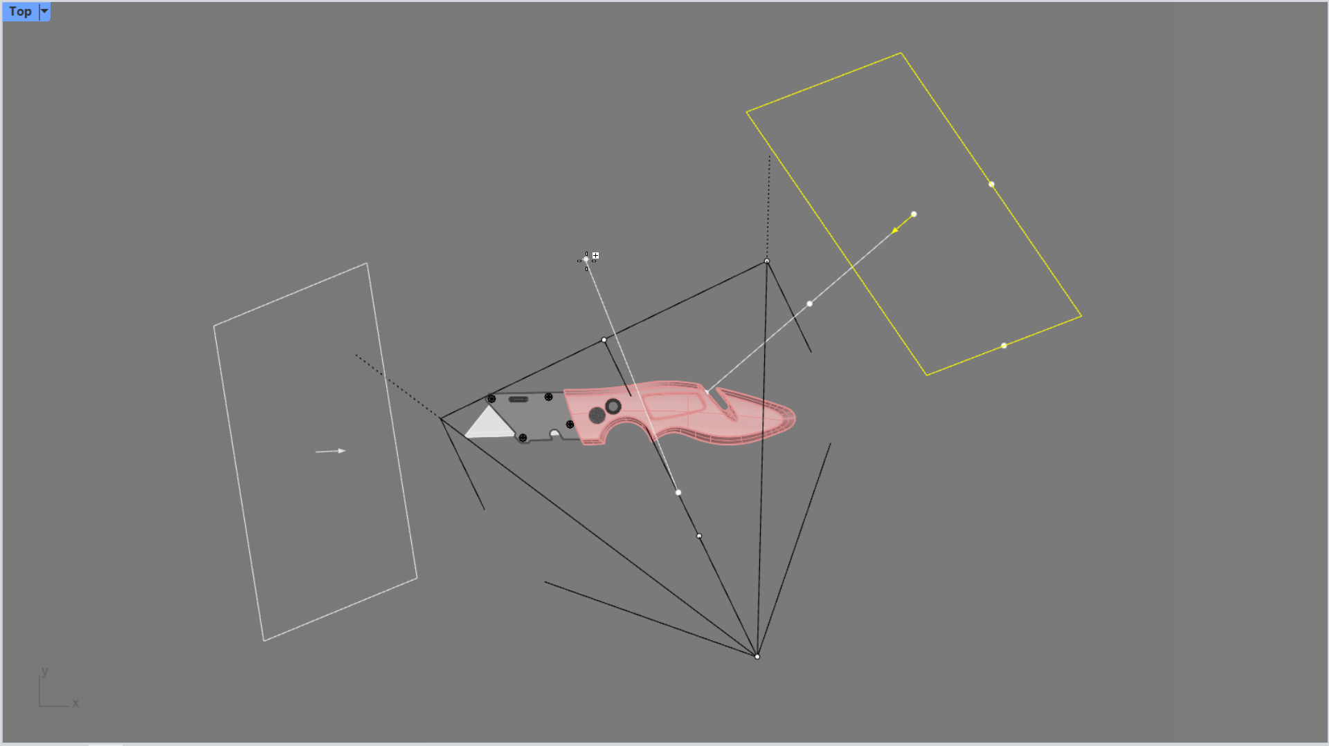
- Change the viewport to Raytraced . We’ll obtain a more accurate calculation of the scene.
- Go the
Lights
panel. There are two Unnamed lights listed. These correspond to the rectangular lights we added.
- Click to change their names. The first one to Front and the second one to Back.
- For the Front, click in the Intensity setting and change it to 0.8.
- For the Back, click in the Intensity setting and change it to 0.6. You’ll notice how the Raytraced viewport updates.
- Continue playing with the light settings in the panel. Adjust the Falloff and Color for each light. This will set a different quality to the scene.
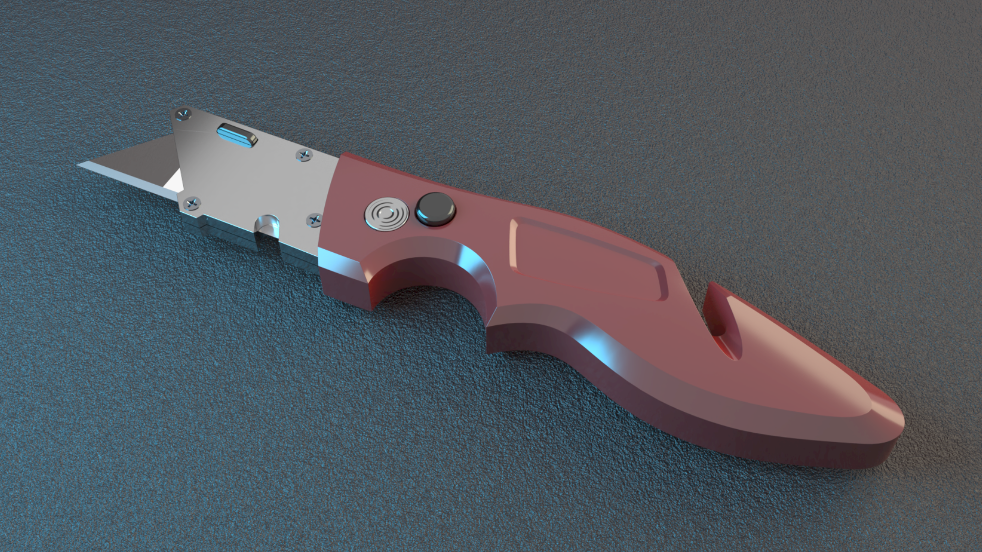
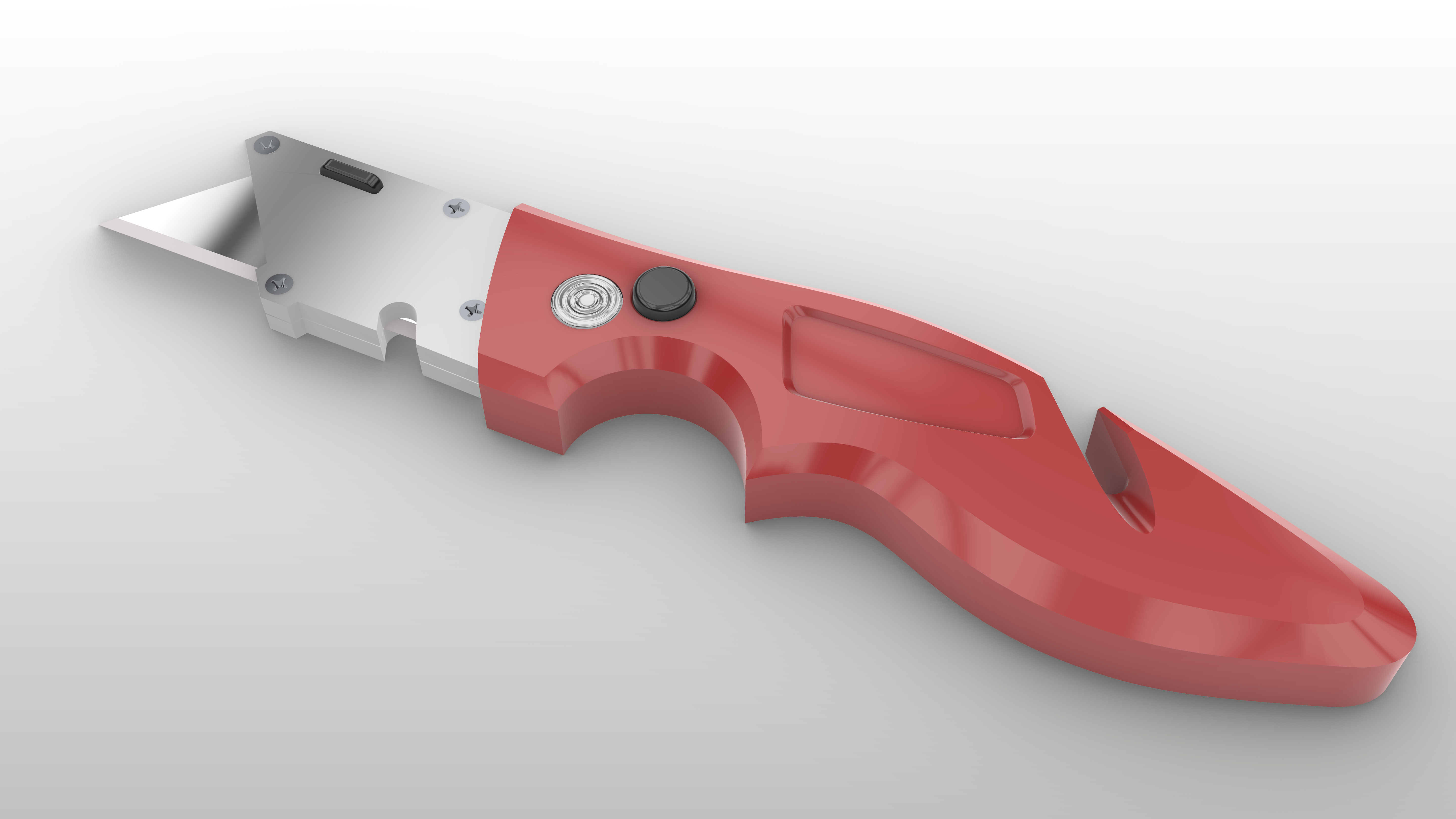
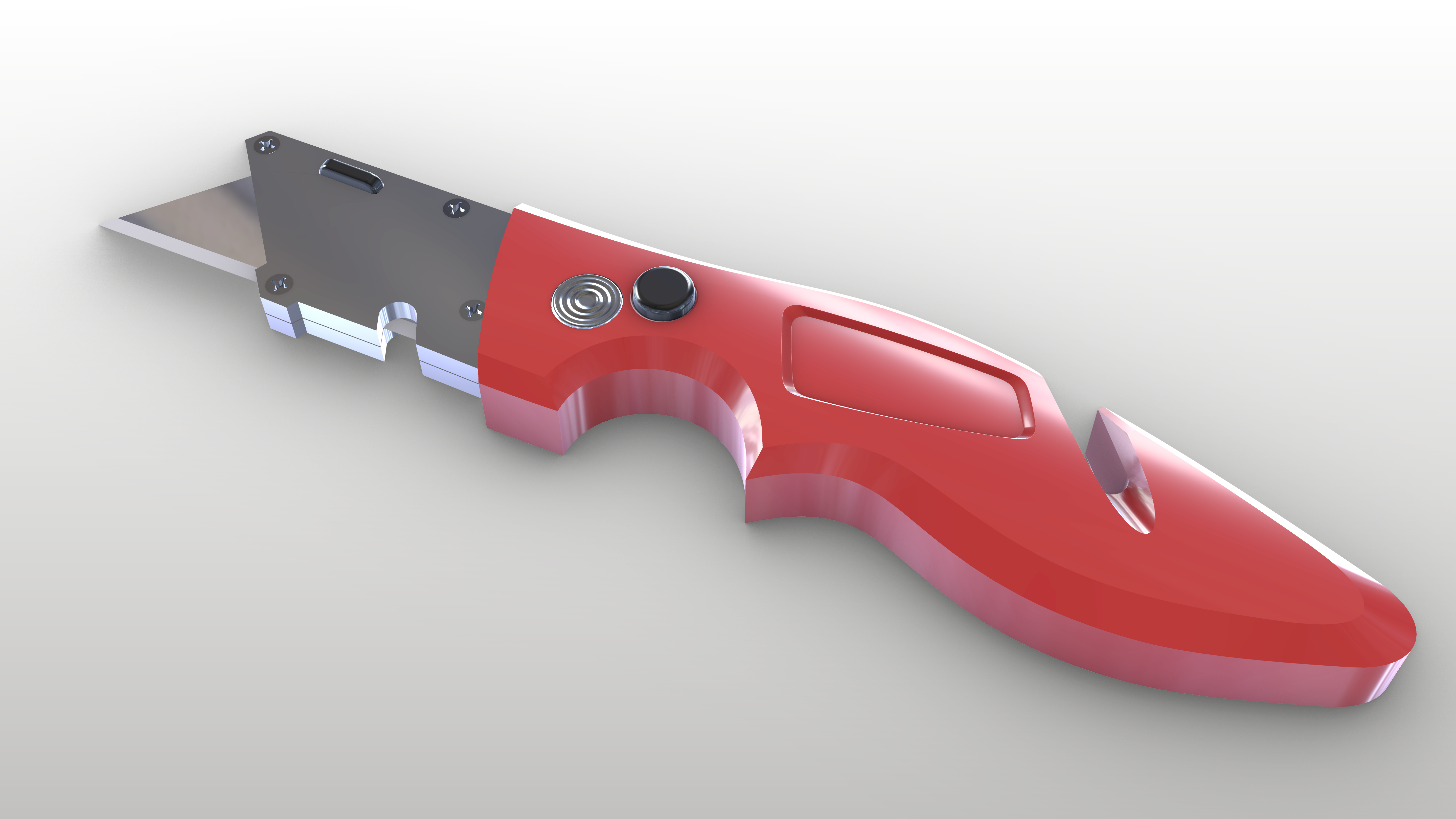
- Try it on your own! open Lights-Utility-Knife-Finish.3dm in Rhino . This file contains the lights set up to produce the image above.
Render
There are several ways of outputting a final rendered image. Up to now, we’ve been previewing the results using
Rendered
and
Raytraced
display modes in the viewport. You can use the
![]() ViewCaptureToFile
to generate an image file from the viewport results.
ViewCaptureToFile
to generate an image file from the viewport results.
If you wish to have more control over the size and quality of a render, you can select from a variety of options in
![]() Rendering
panel, under the Resolution and Quality section. These are the options used once you run the
Rendering
panel, under the Resolution and Quality section. These are the options used once you run the
![]() Render
command.
Render
command.
