Rhino offers a suite of tools to help you create drawings. These can be used in different stages of the creation process, such as for manufacturing or presentation purposes. There are different ways of creating a drawing in Rhino.
In this chapter, we learn the following process:
TO IMPROVE!!!:
- Create the floor plan
- Create a Layouts
- Add a Detail view
- Add a Titleblock
- Add dimensions and annotations on the Layout
- Create a
- Create a Section of the 3D model
- Add hatches
- Learn about NamedViews
- Print to PDF
Create the Floor Plan
We will start by creating the Floor Plan drawing of our building. We will add the 2D representations of the doors separately. These have been included as
![]() Block
objects in the Rhino file.
Block
objects in the Rhino file.
Create the Section
We will use a
![]() ClippingSections
object to clip the scene and see into the Floor Plan of the building.
ClippingSections
object to clip the scene and see into the Floor Plan of the building.
- Open Drafting-Architectural.3dm in Rhino .
- Run the
 ClippingSections
command.
ClippingSections
command. - At the Select objects to section. Press Enter for all prompt , press .
- At the Place sections…
prompt
:
- Select the Dir=X and change it to CPlane.
- Type 0,0,1.2. Press . It will place the section 1.2 mts in height.
-
Select
the section and run the
 Flip
command.
Flip
command.
Create the Drawing
We will use
![]() ClippingDrawings
to extract a vector drawing from the
ClippingDrawings
to extract a vector drawing from the
![]() ClippingSections
.
ClippingSections
.
- Make sure the Point Osnap is selected.
- Run the
 ClippingDrawings
command.
ClippingDrawings
command. - At the Select clipping sections prompt , select the SEC_00 section. Press .
- Make sure the Command Prompt options are as follows:
( Angle=0 PrintWidth=ByLayer DisplayColor=ByLayer ShowHatch=Yes ShowSolid=No AddBackground=Yes Projection=Parallel AddHidden=Yes AddSilhouette=Yes ShowLabel=No ApplyToAll=No )
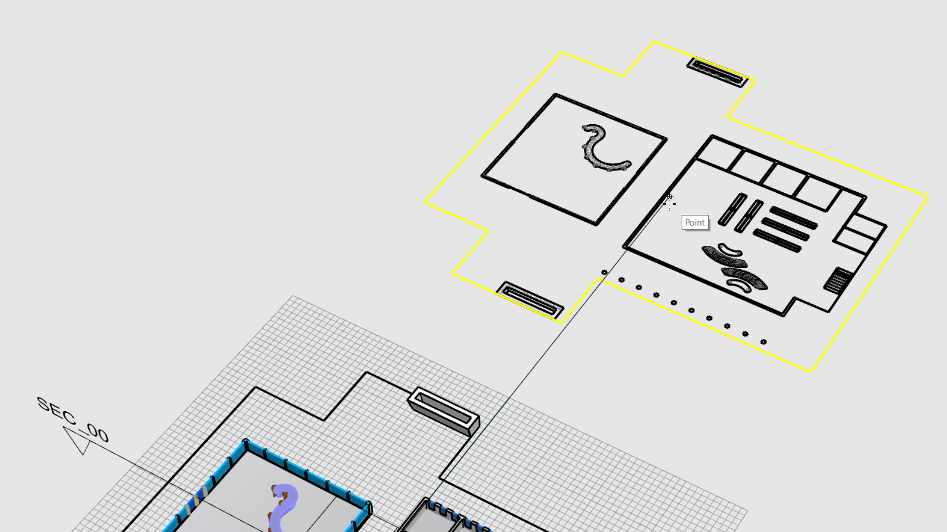
- At the Placement point
prompt
, snap to the point behind the building.
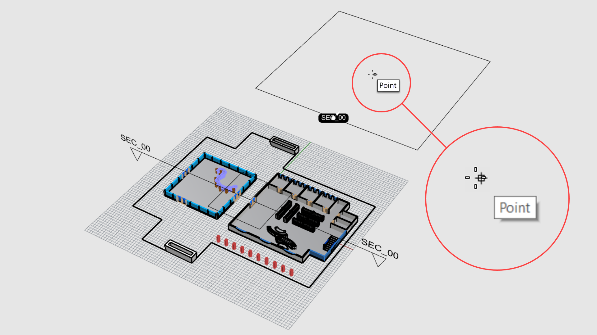
- The vector drawing for the floor plan is created!
- Select the curve representing the roof silhouette.
- Run the
 Copy
command.
Copy
command. - At the Point to copy from prompt , type 0.
- At the Point to copy to prompt , snap to the point behind the building.
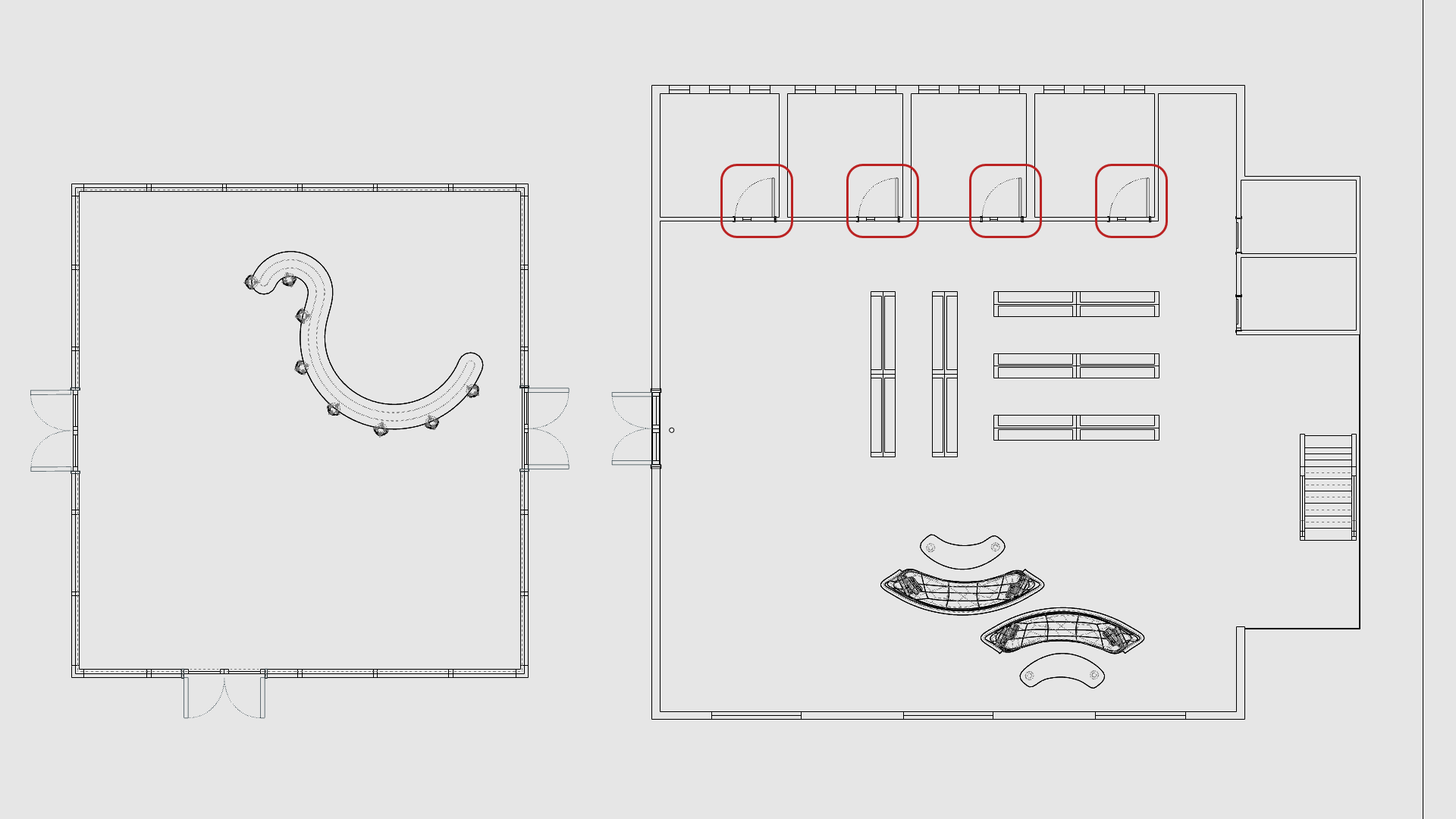
Add 2D Door Symbols
- Use the Viewport Tabs to go back to the viewport.
- Make the 2D Symbols layer current
- Zoom-in to the 2D representation of the curtain wall.
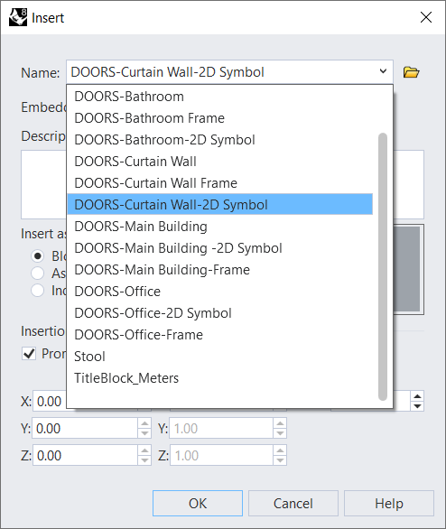
- Run the
 Insert
command.
Insert
command. - Under the Name dropdown list, select DOORS-Curtain Wall-2D Symbol and press .
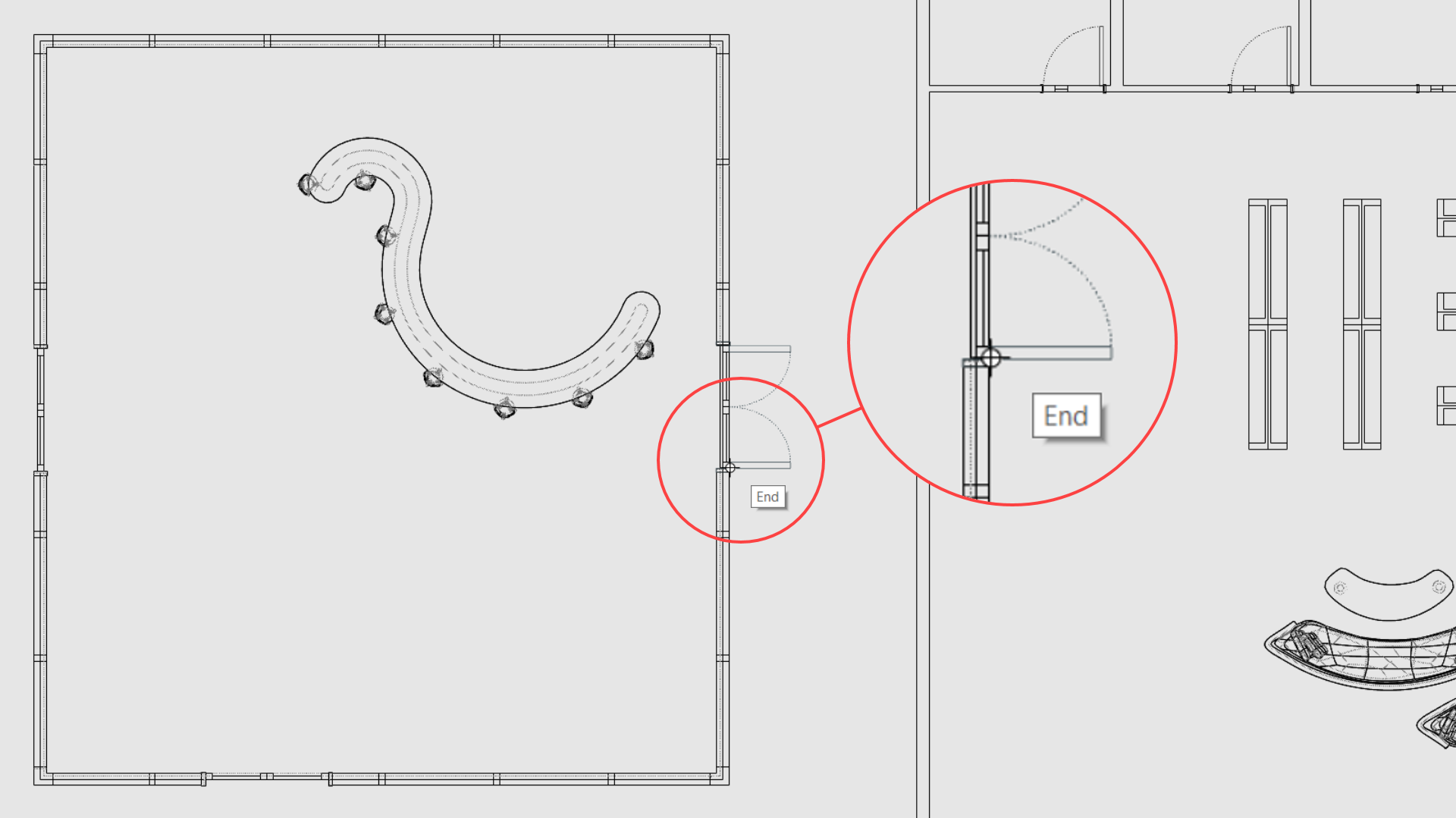
- At the Insertion point prompt , snap as shown:
- Continue adding the 2 other 2D doors for the curtain wall. You’ll have to
 Rotate
or
Rotate
or
 Mirror
the result after inserting.
Mirror
the result after inserting.
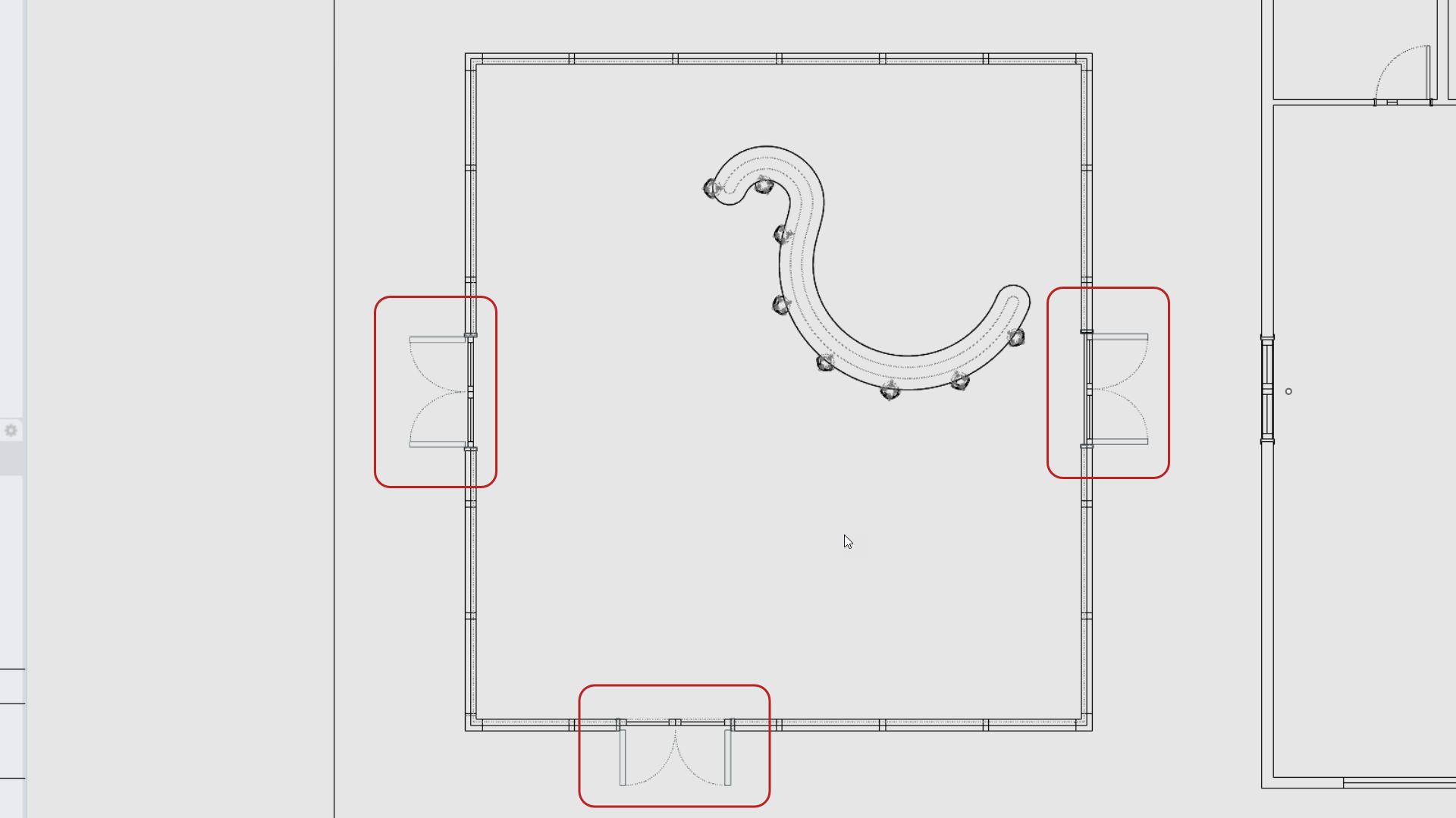
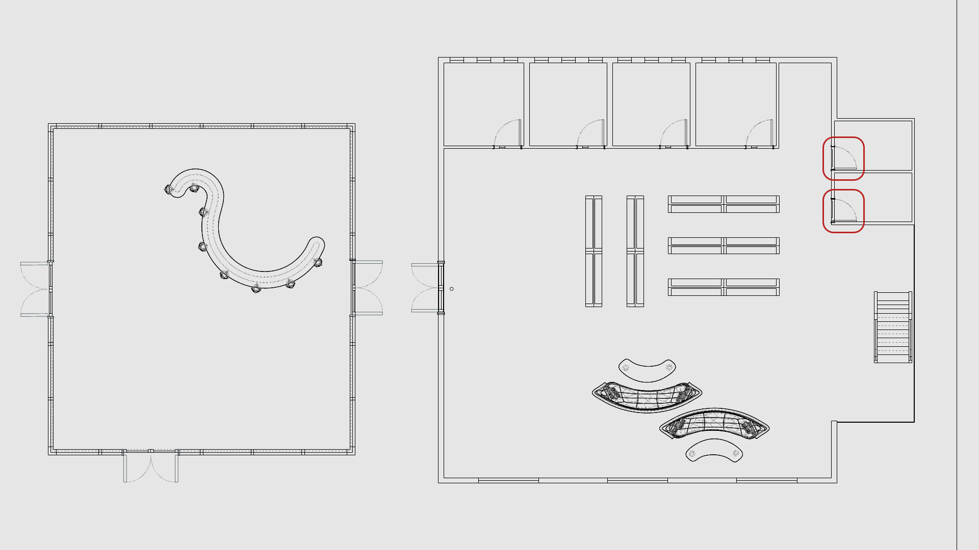
-
Insert
the DOORS-Main Building-2D Symbol block at the following location:
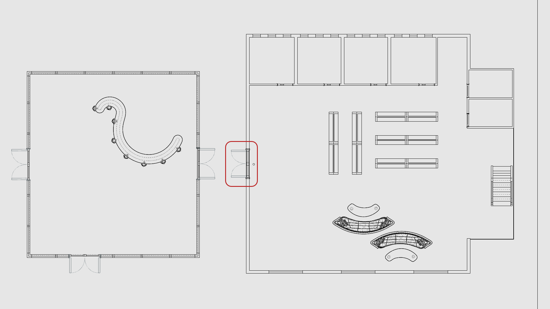
- Next,
Insert
the DOORS-Office-2D Symbol block at the following location:
- To end with 2D door symbols,
Insert
the DOORS-Bathroom-2D Symbol block at the following location:
Create the Layout
The
![]() Layout
command creates a “paper space” that mimics a physical page, as you would use for printing technical drawings. You can set the size and orientation of your page and add viewports called Details, that look into the model.
Layout
command creates a “paper space” that mimics a physical page, as you would use for printing technical drawings. You can set the size and orientation of your page and add viewports called Details, that look into the model.
In this exercise, we will learn how to create a
![]() Layout
with 1
Layout
with 1
![]() Detail
view and add a Titleblock.
Detail
view and add a Titleblock.
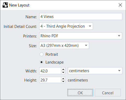
Create a Layout
- Make the Floor Plan layer current .
- Run the
 Layout
command. This opens the New Layout dialog box.
Layout
command. This opens the New Layout dialog box.
- For the Name, type Floor Plan.
- For the rest of the settings, make sure they match the following:
- Press to close the New Layout dialog box.
- The Layout has been created with 1 rectangle that defines the
 Detail
view.
Detail
view. - Double-click inside the Top Detail view to access Model Space.
- Pan until you center the Floor Plan inside the Detail.
- Double-click to go back to the Layout.
- Select the Top Detail view rectangle.
- In the
 Properties
panel, on the
Detail
page, set the Scale Value as follows:
Properties
panel, on the
Detail
page, set the Scale Value as follows:
- For centimeters on page keep it at 1
- For meters in model set it to 1.5
- Press to validate.
-
Select
the
Detail
view.
- In the
Properties
panel, select the Lock Viewport box.
Add the Titleblock
- Make the TitleBlock layer current .
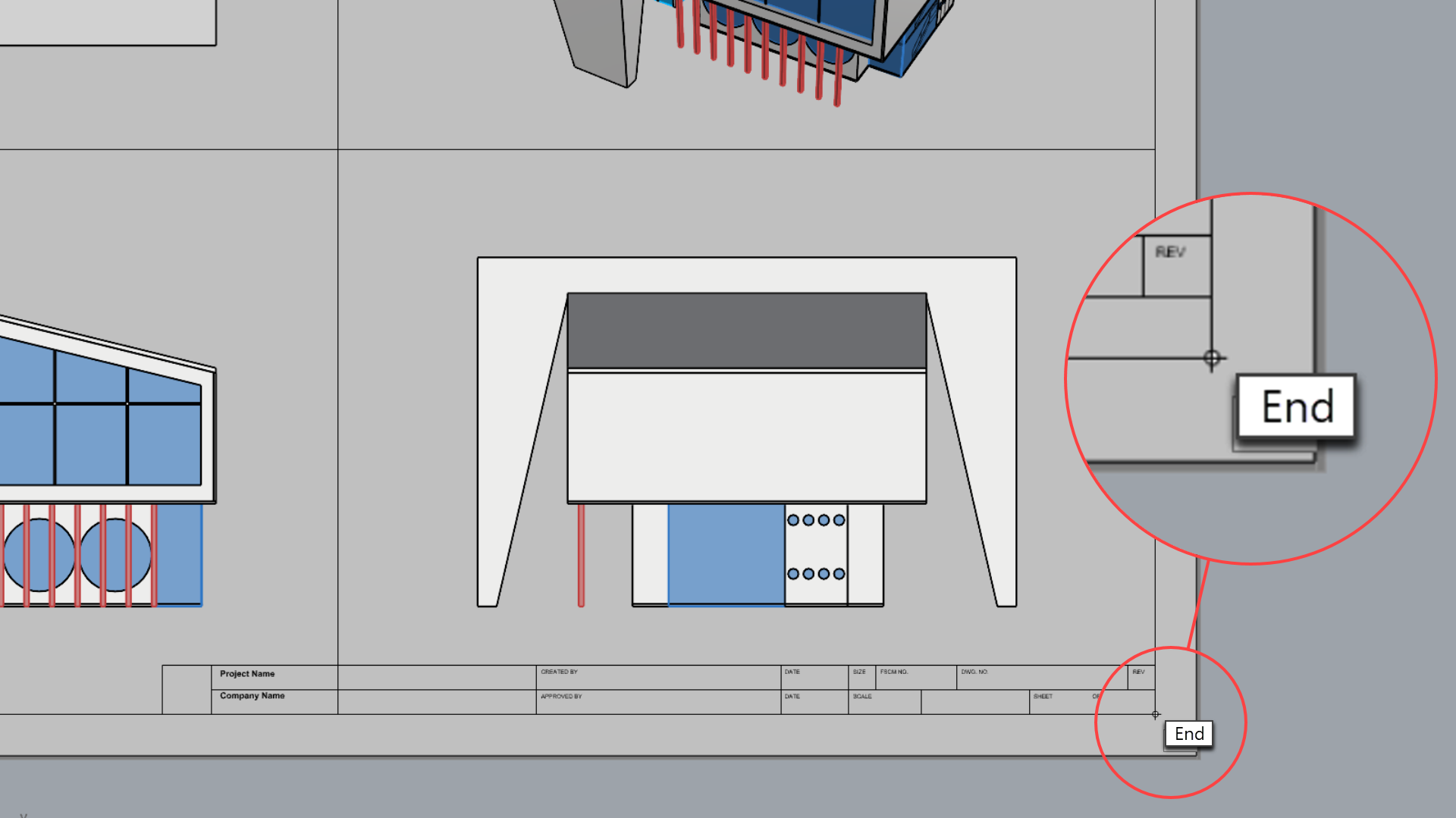
- Make sure the End Osnap is selected.
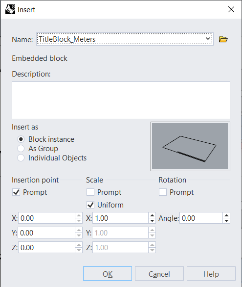
- Run the
Insert
command.
- Under the Name dropdown list, select TitleBlock_Meters and press .
- At the Insertion point
prompt
, snap to the bottom-right corner of the bottom-right Detail view.
- Zoom-in to the TitleBlock. It is a
 Block
composed of text and lines.
Block
composed of text and lines. - Double-click on it to enter
 BlockEdit
mode. In this mode, you can modify the geometry contained inside the block. You can also add or remove elements.
BlockEdit
mode. In this mode, you can modify the geometry contained inside the block. You can also add or remove elements. - Press
to close the Block Edit dialog.
What are Blocks?Blocks are groups of objects that act as a single object. Blocks are useful for repeated objects such as symbols or components. An advantage of using blocks for repeated content is that they require less memory. In addition, you can redefine a block and all instances placed in the model will update.
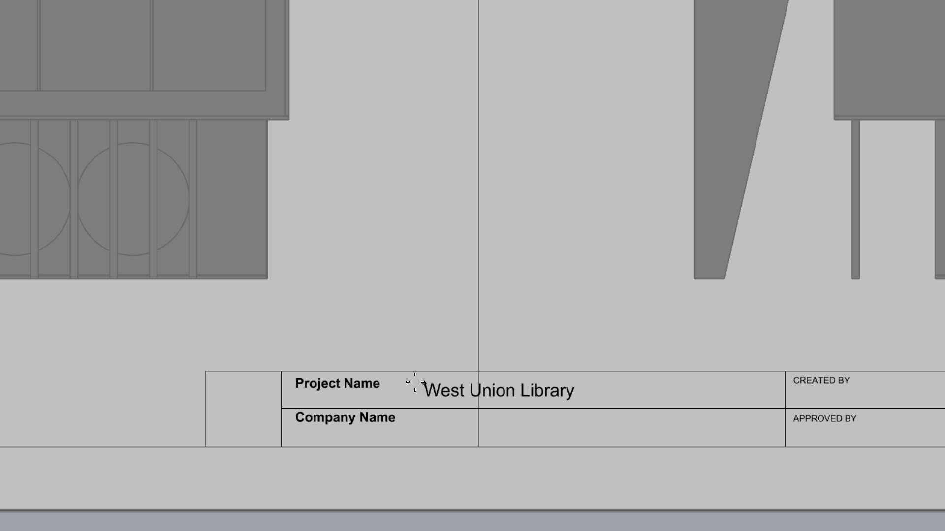
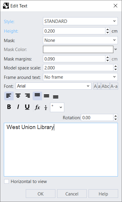
- Run the
 Text
command. This opens the Edit Text dialog box.
Text
command. This opens the Edit Text dialog box.
- For the Style, make it STANDARD.
- For the Height, type: 0.2
- In the Text box, type West Union Library.
- Press to close the Edit Text dialog.
- At the Text location
prompt
, click to place it inside the Project Name area.
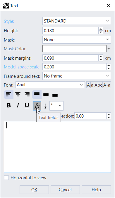
- Run the
Text
command again.
- In the Edit Text dialog box, delete the current text, then:
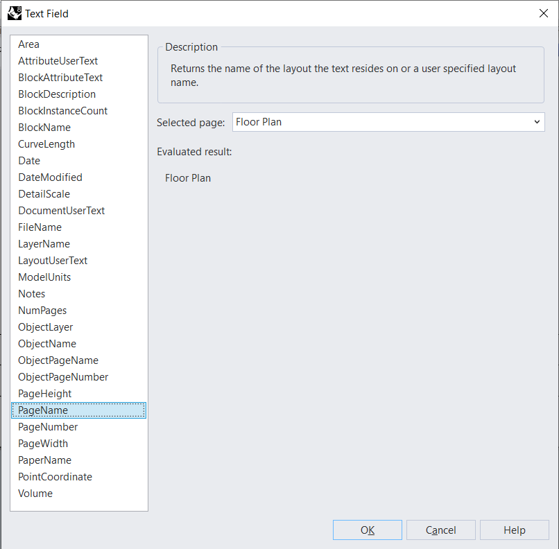
- Select the Text Fields icon.
- In the Text Field box, select PageName.
- Press twice to close both boxes.
- At the Text location
prompt
, select a point of your choice in the Titleblock.
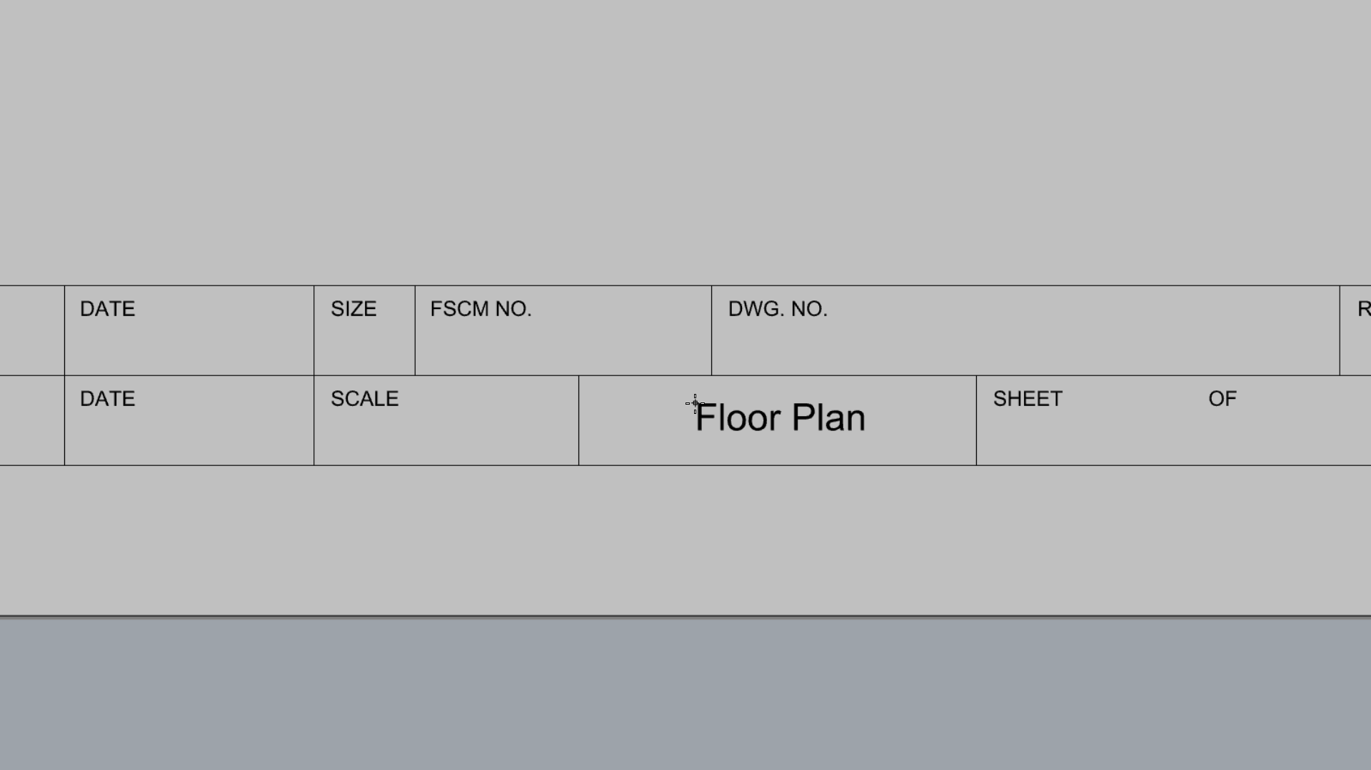
- Notice how changing the Layout name in the Viewport Tabs updates the Text Field in the TitleBlock.
- Try it on your own! Continue adding text to the different fields of the TitleBlock.
Add the Logo
- Download Bolten Logo.
- Run the
 Picture
command.
Picture
command. - In the Open Bitmap dialog, browse to your Downloads folder. The bolten-logo.png file should be located there.
- Double-click on it to select it.
- In Rhino, at the First corner of picture prompt , snap to the bottom-left corner of the logo square in the TitleBlock.
- At the Other corner or length
prompt
, snap to the diagonal corner.
Add Dimensions
In this exercise, we will learn how to use Linear Dimensions, to annotate the Floor Plan drawing. We will also learn how to modify dimensions thorugh their global settings in the Annotation Style.
Add Dimensions
- Open Drafting-Architectural-Layout.3dm in Rhino if you haven’t followed the steps above.(Drafting-Architectural-Layout.3dm) if you haven’t followed the exercise above.
- Add a Layer and name it Dimensions 1.
- Make it current .
- Make sure End Osnap is selected.
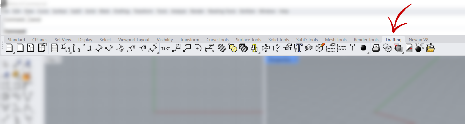
- Go to the Drafting Tab .
- Run the
 Dim
.
Dim
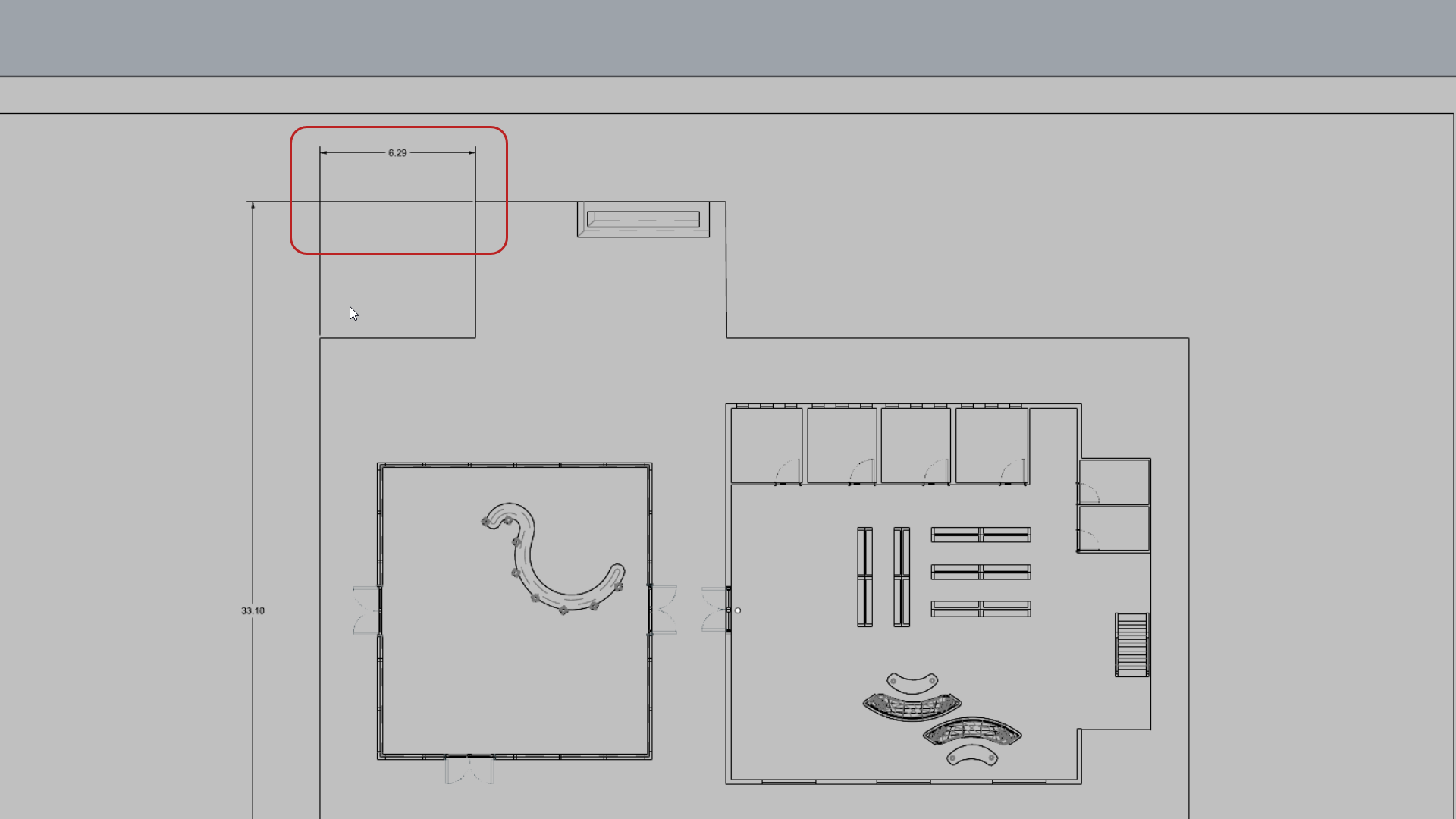
. - At the First dimension point prompt , snap to the end point of the concrete roof.
- At the Second dimension point prompt , snap to the opposite end of the concrete roof.
- For the offset distance, drag the mouse to the left, type 6 and press .
- Then click in the view to end the command.
- Run the
Dim
comand again.
- Follow the
prompts
to place the dimension at the left end of the roof.
- Press
to run the
Dim
again. This time, select the Continue option in the
Command Prompt
:
Continue=yes - The command runs in a loop so you can continue placing dimensions from the last point.
- Press when done.
Modify Dimensions
Dimension settings are controlled by the Annotation Style in a 3DM file. Each file contains preconfigured styles. You can modify the settings in the Annotation Style page of the
![]() DocumentProperties
. This is a global control and will affect existing and future dimensions added to the file.
DocumentProperties
. This is a global control and will affect existing and future dimensions added to the file.
In this exercise, we will learn how to modify the STANDARD dimension style, used to create the dimensions in this file..
- Stay in the Floor Plan view.
- Select any dimension.
- Go to the
Properties
panel. You should see the Dimensions properties.
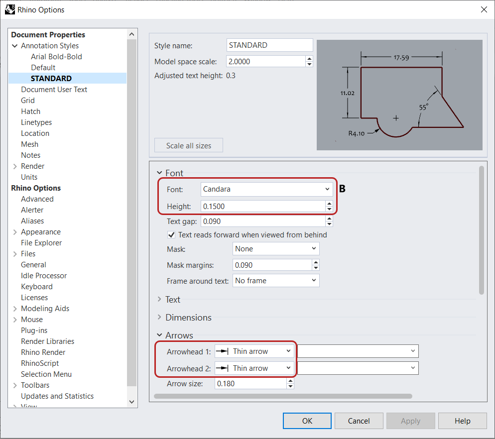
- Select the Edit Style button at the bottom. This will open the Annotation Style page for STANDARD.
- Under Font:
- Change the Font to Candara.
- Change the Height to 0.4.
- Under Arrows:
- Change the Arrowheads 1 to Thin arrow.
- Arrowheads 2 should inherit the change.
- Chagne Arrow size to 0.6.
- Press to close the dialog. Notice the changes to the annotations in the Layout.

Create an Elevation
We will create a second section to generate the Elevation drawing. We will learn about assigning lineweights to obtain visual hierarchy. Then, we will add a few annotations to inform the drawing about construction materials.
Create the Elevation Drawing
We will use a
![]() ClippingSections
object to clip the scene and see into the Floor Plan of the building.
ClippingSections
object to clip the scene and see into the Floor Plan of the building.
- Open Drafting-Architectural-Elevation.3dm in Rhino if you haven’t followed the steps above.
- Make the Elevation layer current .
- Run the
ClippingSections
command.
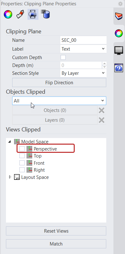
- Use the Viewport Tabs to go back to the viewport.
- select the SEC_00 clipping section.
- In the
Properties
panel, under Views Clipped, deselect Perspective.
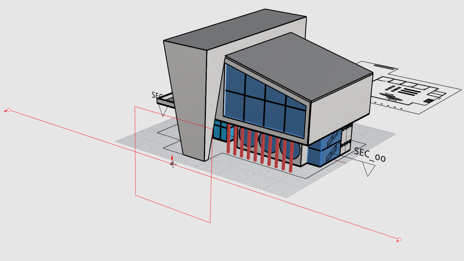
- Run the
ClippingSections
command.
- At the Select objects to section. Press Enter for all prompt , press .
- At the Place sections prompt , make sure Dir=X.
- Right-click to place the section in front of the façade.
-
Select
the section and run the
Flip
command.
- Run the
ClippingDrawings
command.
- At the Select clipping sections prompt , select the SEC_01 section. Press .
- Make sure the Command Prompt options are as follows:
( Angle=0 PrintWidth=ByLayer DisplayColor=ByLayer ShowHatch=Yes ShowSolid=No AddBackground=Yes Projection=Parallel AddHidden=No AddSilhouette=Yes ShowLabel=No ApplyToAll=No )
- At the Placement point
prompt
, select a point behind the Floor Plan drawing.
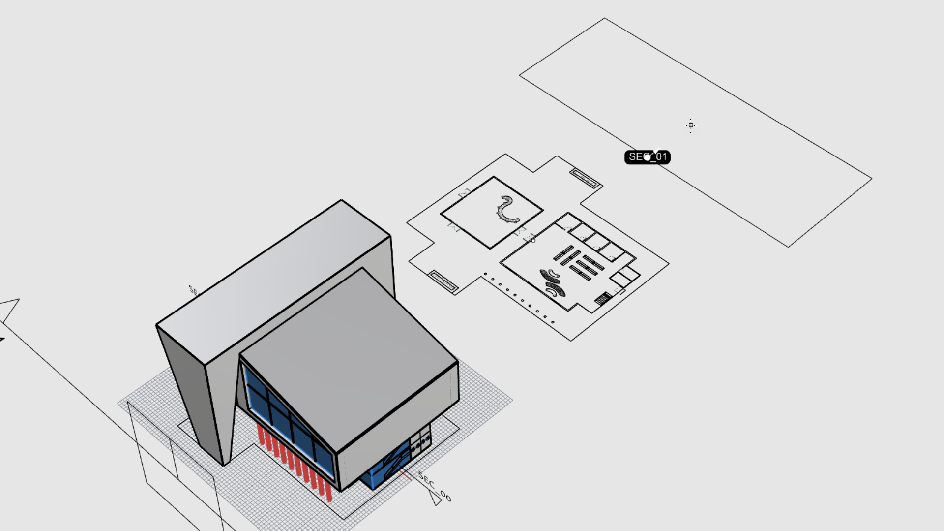
- The vector drawing for the elevation is created!
Duplicate a Layout
- Right-click on the Floor Plan Viewport Tab .
- Select Move or Copy.
- In the Move or Copy dialog, select:
- (move to end)
- Create a copy
- Click OK to close the dialog.
- Double-click the Floor Plan - Copy tab and rename it to Elevation A.
- Run the
 SelDim
command and
SelDim
command and
 Delete
them.
Delete
them.
Configure the Detail
- Run the
 SelDetail
command.
SelDetail
command. - In the
Properties
panel, unselect Lock Viewport.
- Double-click inside the Detail view.
- Pan until the Elevation drawing is visible.
- Double-click to go back to the Layout view.
- Select the Detail again.
- In the
Properties
panel, on the
Detail
page, set the Scale Value as follows:
- For centimeters on page keep it at 1
- For meters in model set it to 1.2
- Press to validate.
- Select to Lock Viewport.
Assigning Lineweights
To facilitate the process, we’ve created standard lineweights in the Rhino file. You will learn how to assing them to the selected objects.
- Run the
 Linetypes
command to open the Linetypes panel.
Linetypes
command to open the Linetypes panel. - In the
 Layer
panel, select all SEC_01 layers and select the Lock icon. They can now be modified.
Layer
panel, select all SEC_01 layers and select the Lock icon. They can now be modified.
- Double-click inside the Detail view.
- Right-click on the layer SEC_01Silhouette.
- In the context menu, select Select Objects.
- Hold down to add the concrete stucture linework to the selection.
- Go the Linetypes panel.
- Right-click on 0.7 mm and select Assign to selected objects.
- Try it on your own! Continue assigning different lineweights to your drawing.
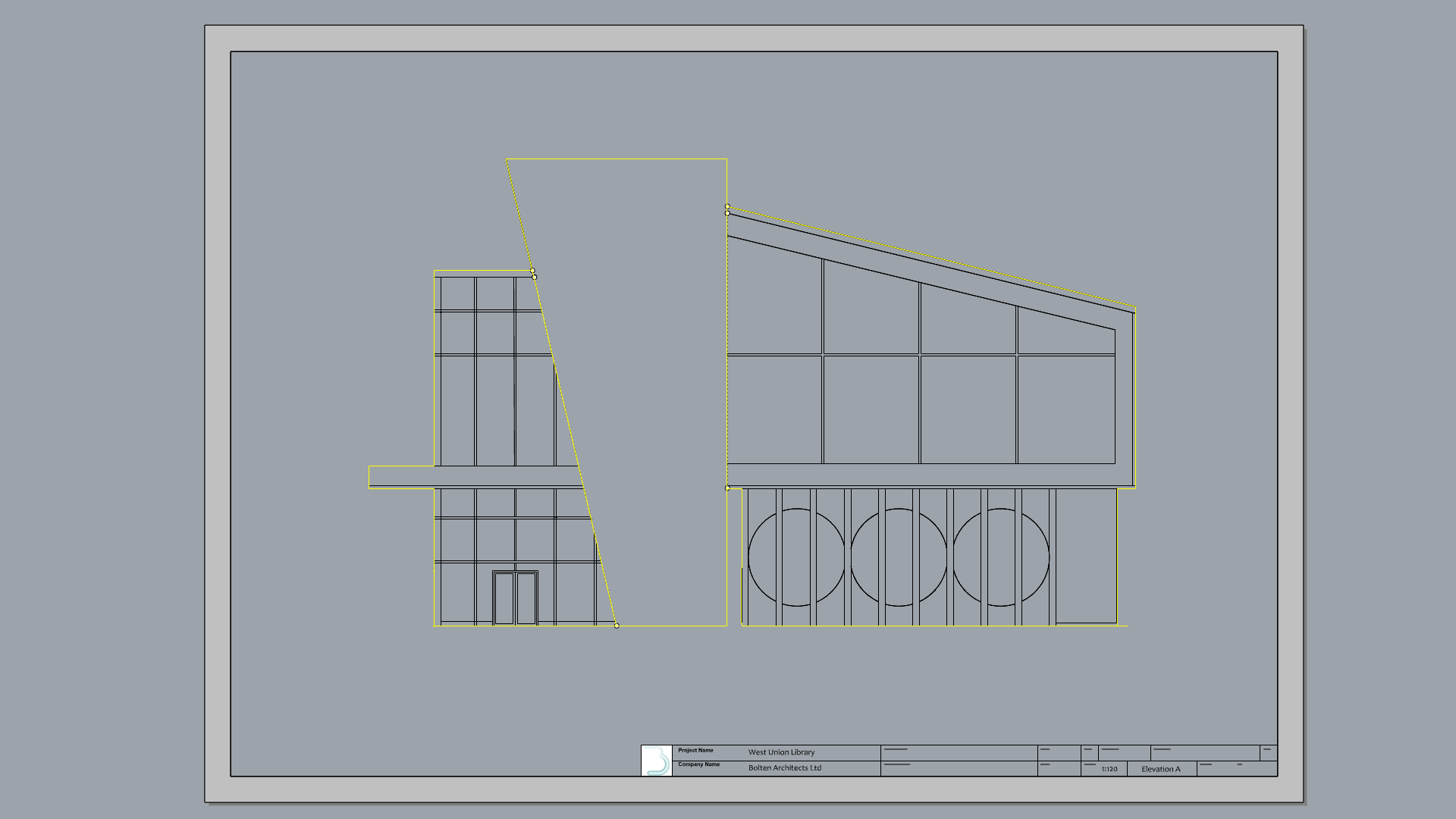
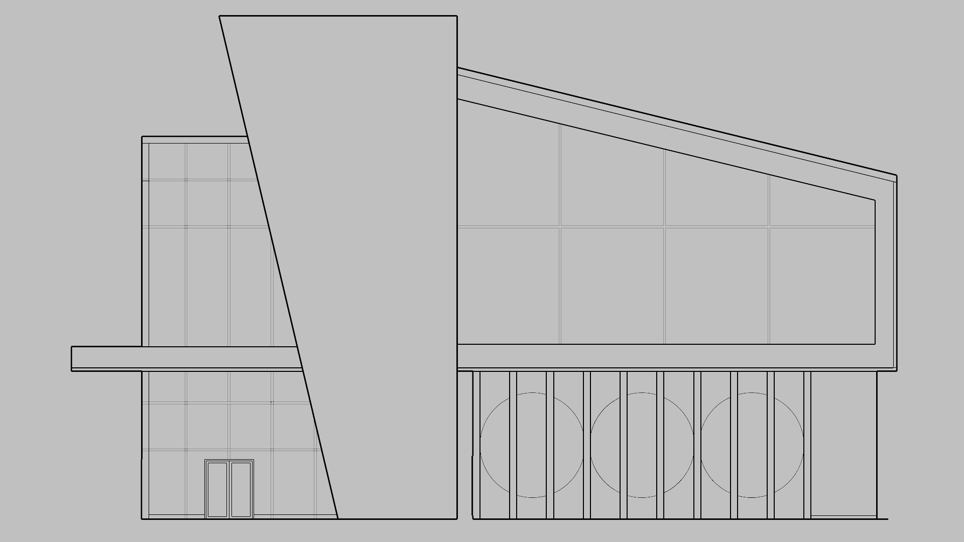
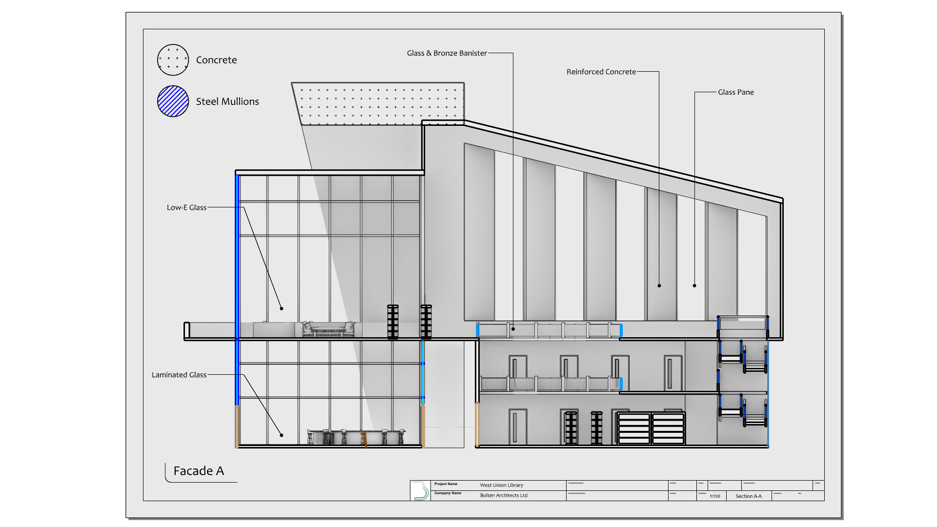
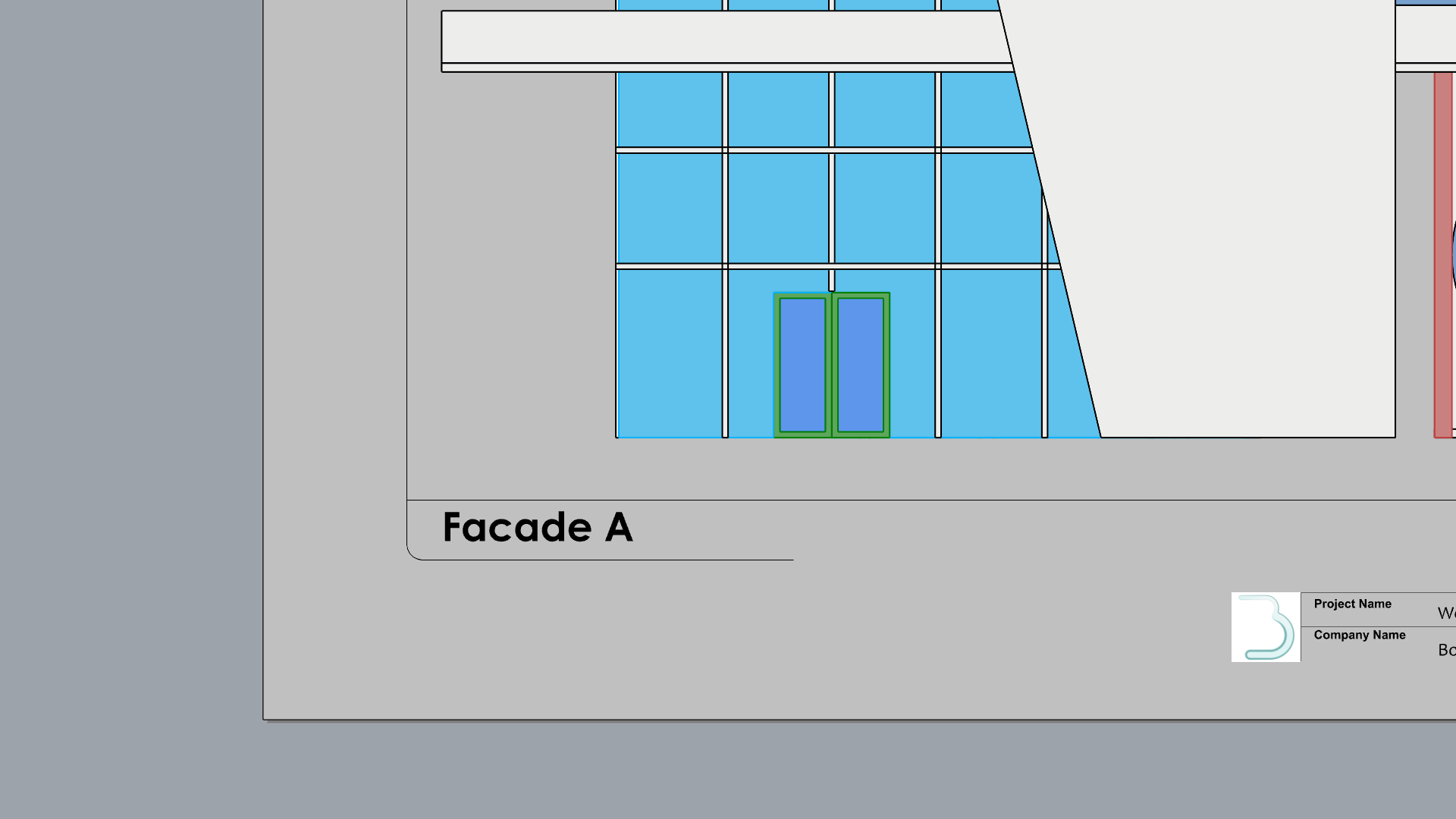
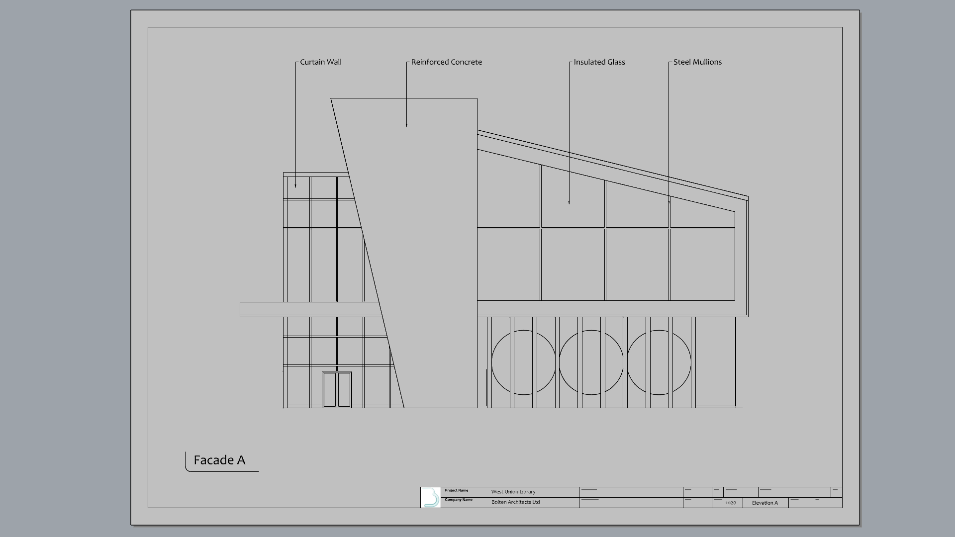
Add Annotations
- Add a Layer and name it Dimensions 2.
- Make it current
- Run the
Text
command.
- In the Text dialog:
- Set the Height to: 0.5
- In the text field type: Facade A.
- Press OK to close the dialog
- At the Text location prompt , select a point on the bottom-left corner of the Detail.
- Feel free to add a linework or other symbols to emphasize the text.
- Zoom to the top of the drawing.
- Run the
 Leader
command.
Leader
command. - At the First curve point prompt , select a point on the curtain wall.
- At the Next curve point prompt , select a point vertically above it, press .
- In the Leader dialog box, type: Curtain Wall. Press OK.
- Continue adding leaders to the other facade elements..
- Use the
Gumball
to Align the Leaders or their
Control Points
to the same height if needed.
Modify the Leader StyleRun the SelLeader command to select all Leaders. Then modify their text size and arrow style in the Object Properties panel.
NOTE To Self:
- This is where I’m at currently!
- Next:
- Working with Drafting-Architectural-Vector_Floor_3.3dm file
- Continue with Sec A-A
- Then Print section
_________________________________________-
Create a Section
Rhino has tools for cutting through the 3D model to create section views.
![]() ClippingSections
and its adjacent commands, help us visualize internal details such as wall thicknesses, interior doors and other elements that are not visible from an exterior view.
ClippingSections
and its adjacent commands, help us visualize internal details such as wall thicknesses, interior doors and other elements that are not visible from an exterior view.
In this exercise, we will learn how to create a section and add it to a Layout. We will also learn how to configure the Section Style, which includes hatches and borders.
Create the Section
- Open Drafting-Architectural-Section.3dm in Rhino if you haven’t followed the steps above.
- Go back to the Perspective viewport using the Viewport Tabs .
- Maximize the .
- Make Section A-A layer current
- Select Mid in the Osnap Control .
- For working clarity:
- Turn off layers : SEC_00, SEC_01 and 2D Symbols.
-
Select
and
 Hide
all other elements in the scene.
Hide
all other elements in the scene.
- Run the
ClippingSections
command.
- At the Select objects to section prompt , press to Select all.
- At the Place section prompt , make sure the options match:
( Dir=X CustomDepth=No Clip=Yes Name=SEC LabelMode=Text SaveToNamedView=Yes Flip=No )
- Then, snap to the mid-point of the concrete roof structure. Press
.
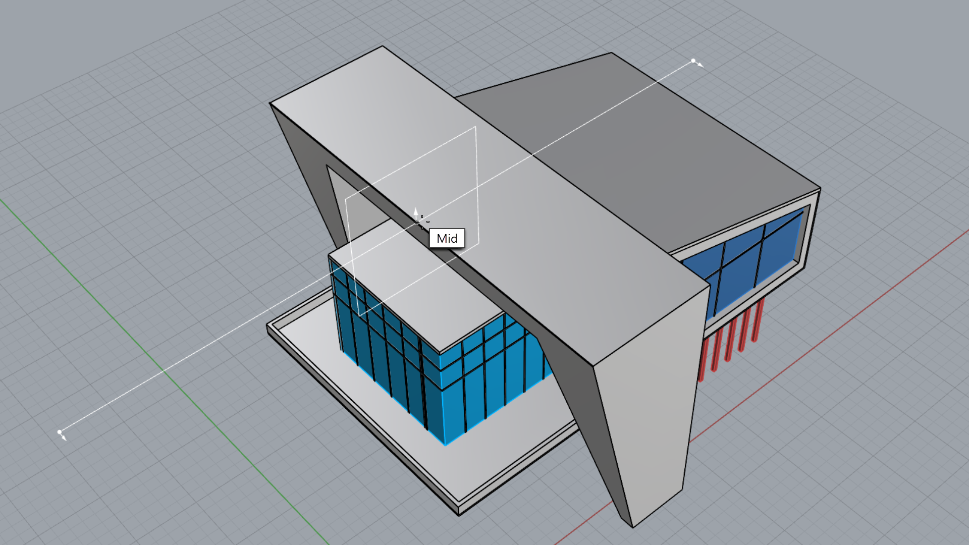
- The building has been clipped and you can see inside.
-
Select
the ClippingSection and
Hide
it.
Add the Section to a Layout
- Create a copy of the Elevation A Layout.
- Rename this Layout Section A-A in the tab .
- Double-click the Facade A text.
- In the Edit Text dialog, replace with Section A-A. Press OK.
- Run the
 SelLeader
command and delete all leaders.
SelLeader
command and delete all leaders. - Select End in the Osnap Control .
- Run the
 Detail
command.
Detail
command. - Select the Add option in the prompt
- At the First corner of rectangle prompt, snap to the top-left corner of the Titleblock.
- At the Other corner or length prompt, snap to the bottom-right corner of the Titleblock.
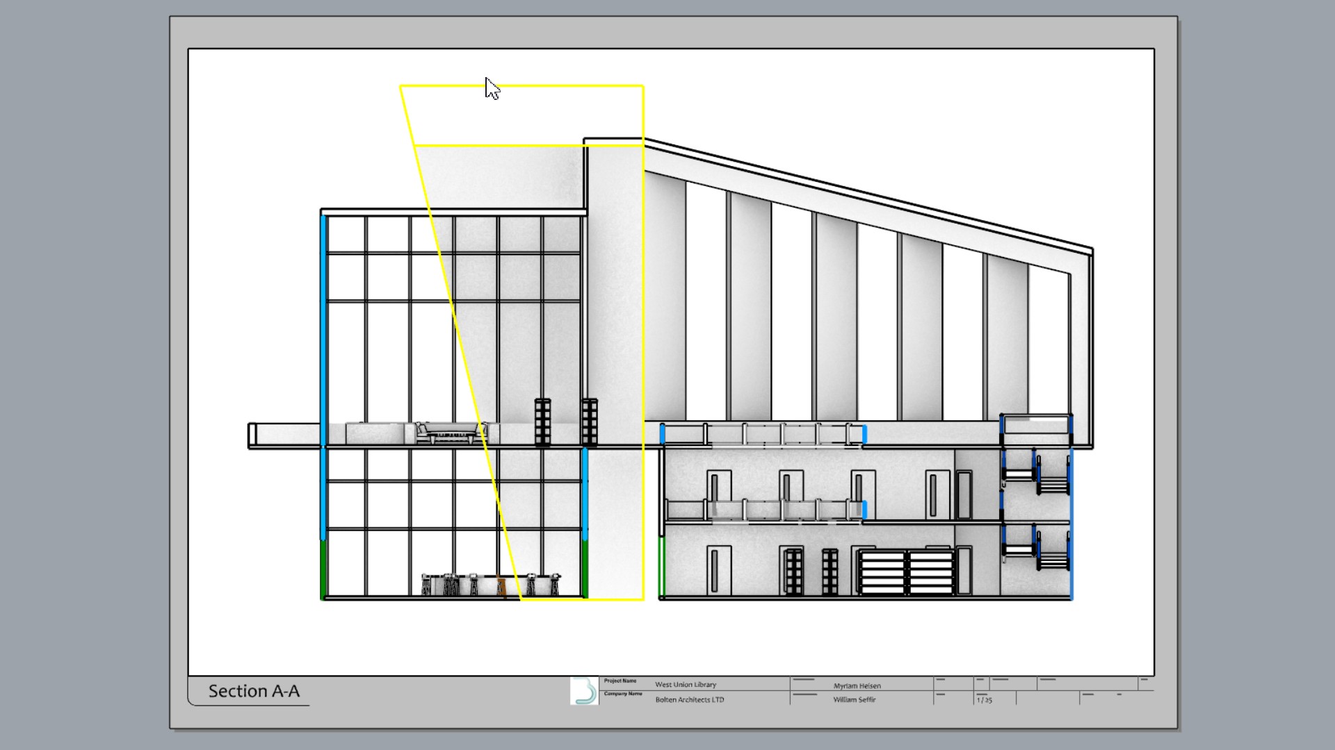
- Run the
 NamedView
command to open the panel.
NamedView
command to open the panel. - Double-click inside the Detail view.
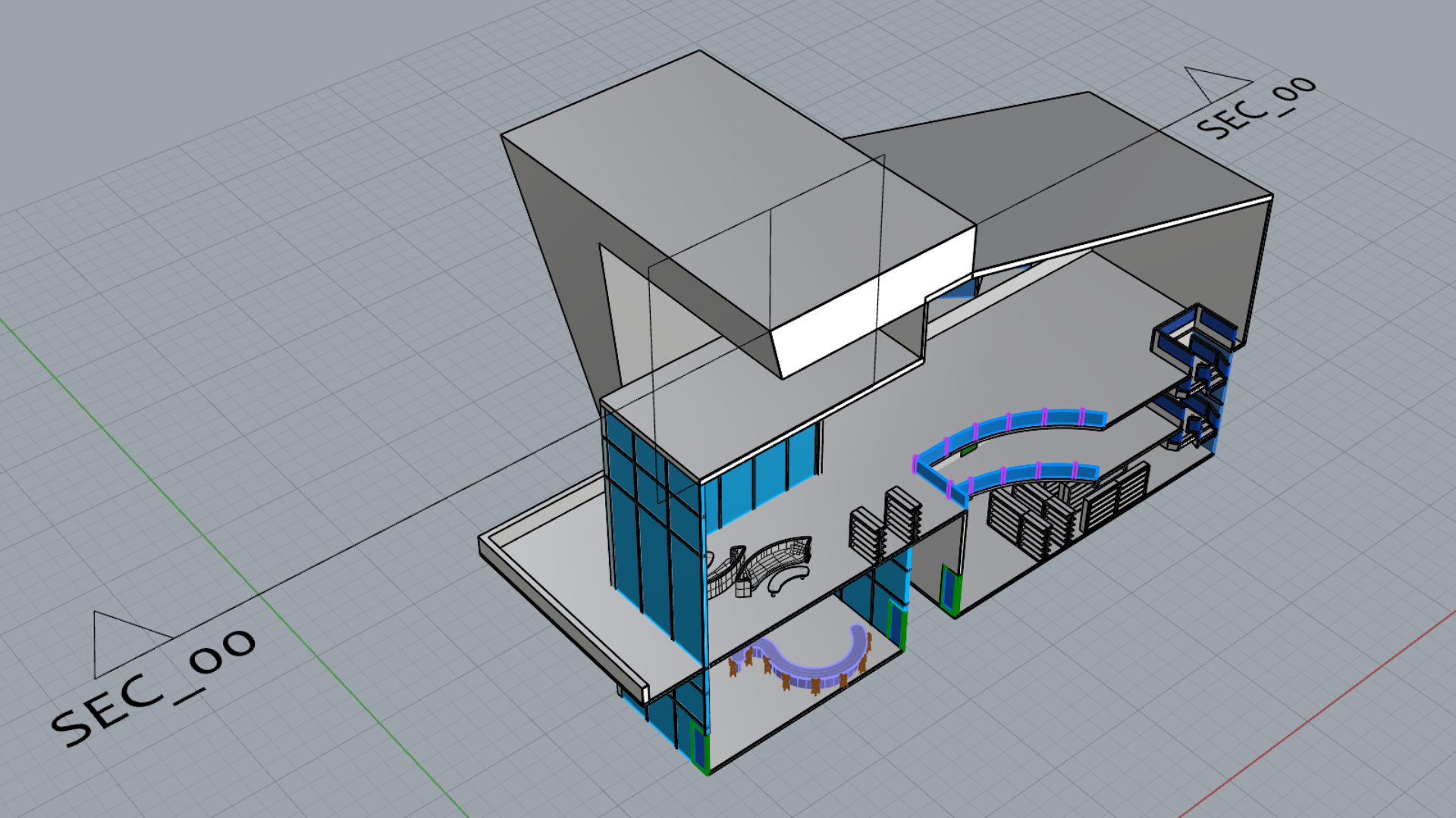
- From the
NamedView
panel, double-click the SEC_00 thumbnail.
Configure the Section Detail
- Select the Detail view.
- In the
Properties
panel:
- Set the scale 1 centimeter on page for 1 meter in model.
- Set the Display Mode to Monochrome
- Select Lock Viewport
Define Section Styles
Section Styles allow you to configure hatch and boundary styles to the sectioned 3D model. A Section Style can be applied to the object, the layer or the clipping section. In this exercise, we will apply the Section Style, per Object and per Layer.
Hatches and Borders per Object:
- Double-click inside the Section A-A Detail.
- Set the Display Mode to Monochrome.
-
Select
the concrete structure element.
- In the
Properties
panel, select the Section Style dropdown list and pick Custom….
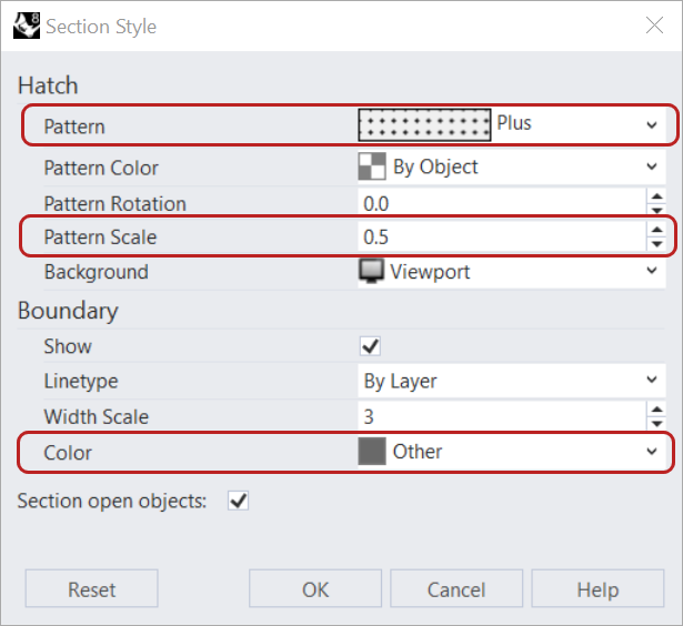
- In the Section Styles dialog:
- For the Hatch Pattern, select Plus from the dropdown list.
- Set the Pattern Scale to 0.5
- For the Boundary Color, select Other and pick a dark grey hue.
- Press to close the Section Style dialog.
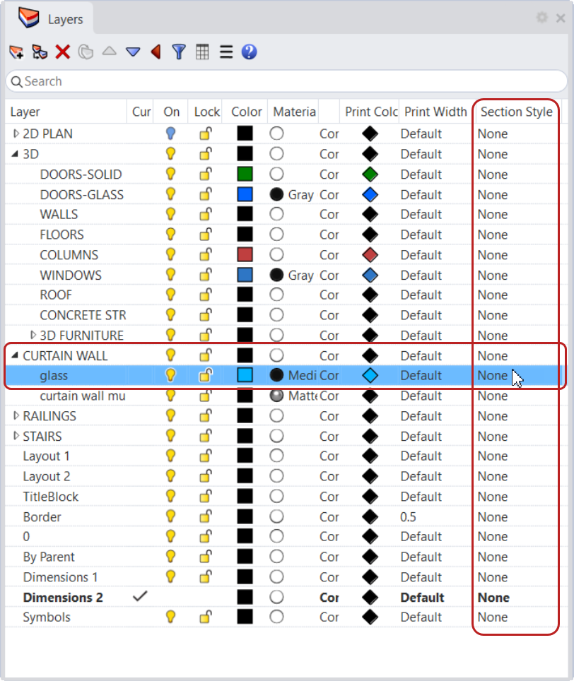
Hatches and Borders per Layer:
- Click on the Perspective tab to go back to Model Space.
- In the
Layer
panel, expand the CURTAIN WALL layer to find the curtain wall mullions sublayer.
- Find the Section Style column of the
Layer
panel.
- Select None to open the Section Style dialog.
Expandíng the Layer PanelYou might need to drag the Layer panel border to find the Section Style column.
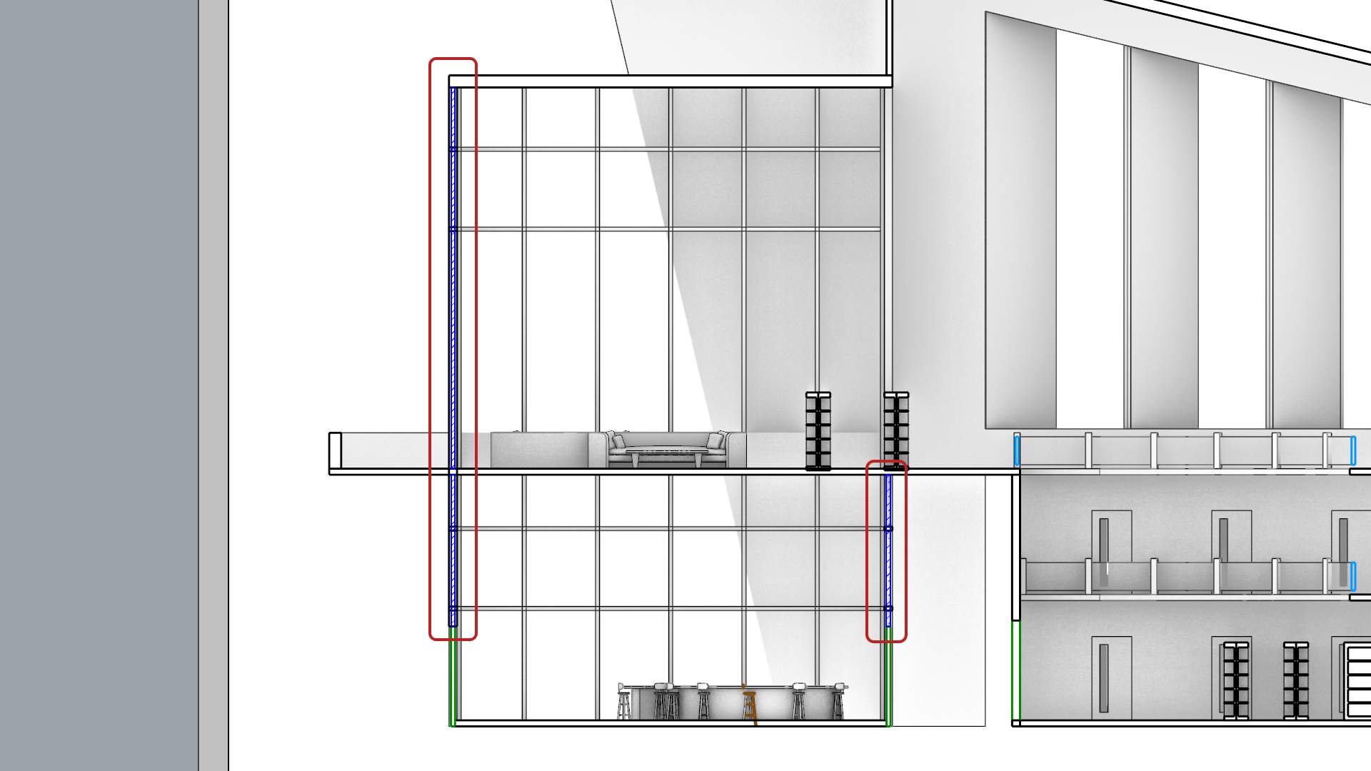
- In the Section Styles dialog:
- For the Hatch Pattern, select Hatch2 from the dropdown list.
- For the Pattern Color, select Blue from the dropdown list.
- Set the Pattern Rotation to 45.
- Set the Pattern Scale to 0.1.
- For the Boundary Color, select Blue from the dropdown list.
- Set the Boundary Width Scale to 2.
- Press to close the Section Style dialog.
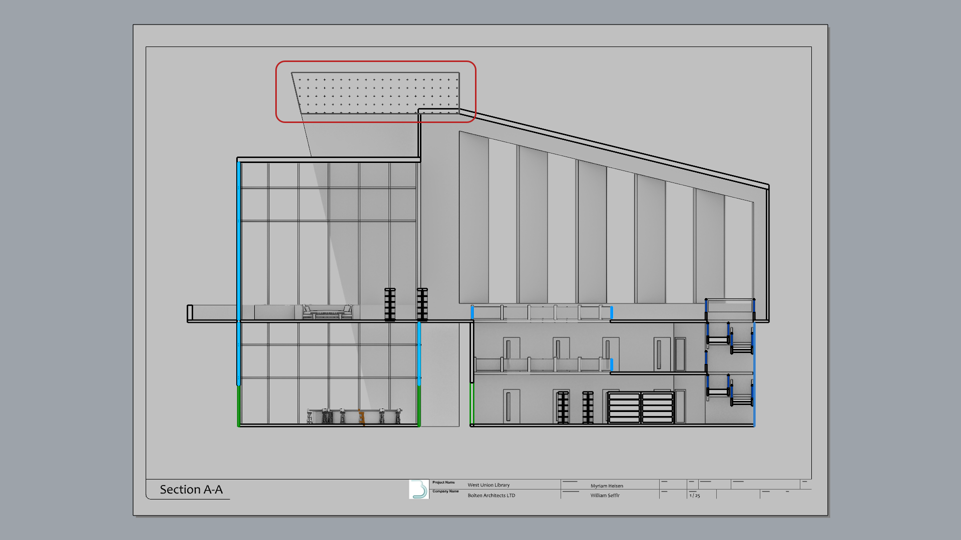
- Zoom-in to the Section A-A Detail to see the result.
- Try it on your own! Keep adding section styles to other objects and layers in the model.

The Section Style is now an attribute of the object or layer. Move or rotate the ClippingSection around, or modify the object, the section views will update in realtime!
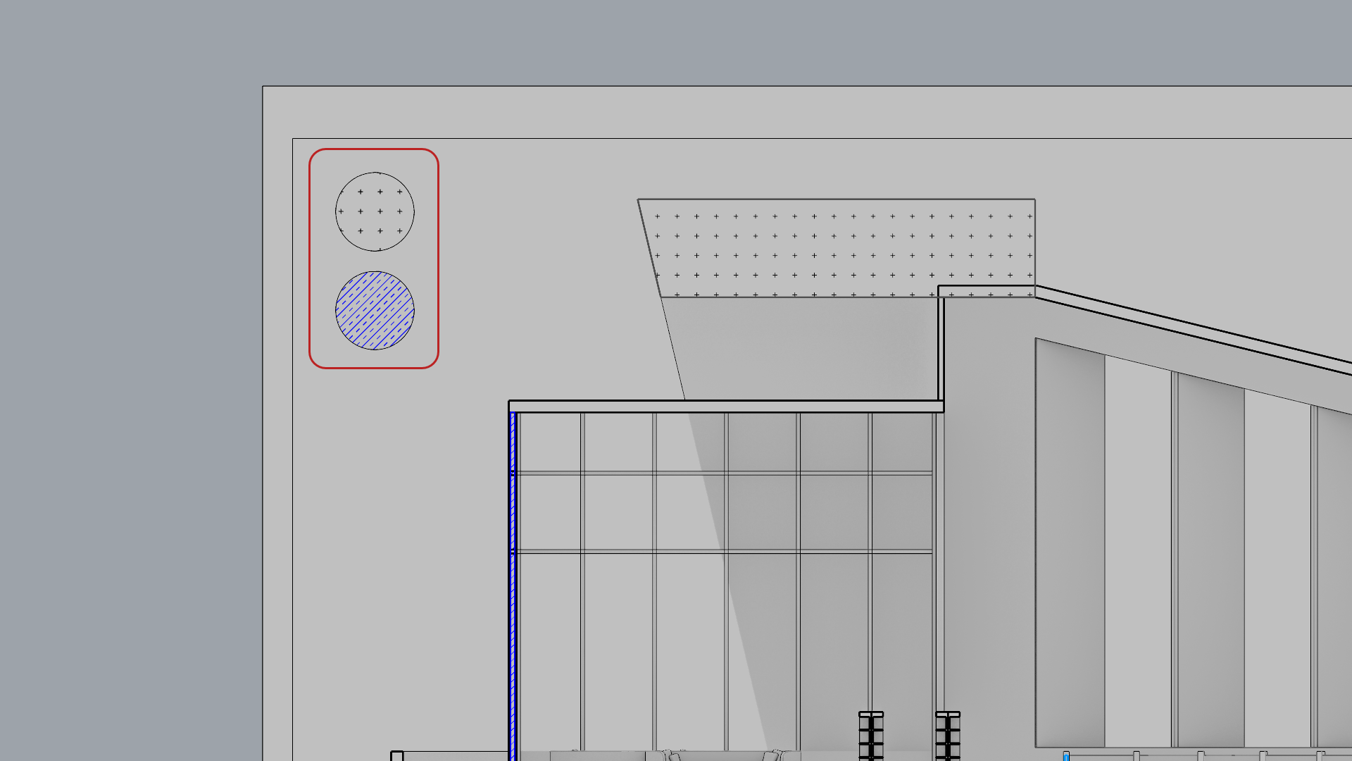
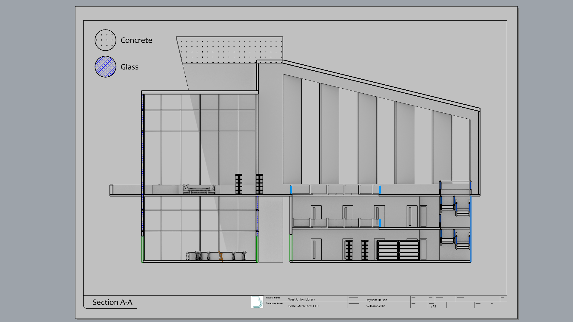
Add a Material Legend
- Go back to the Section A-A tab .
- Run the
 Circle
command. Place it on the top-left corner of the Detail, with a 0.5 cm radius.
Circle
command. Place it on the top-left corner of the Detail, with a 0.5 cm radius. - Copy the circle using Gumball Copy .
- Select the first circle.
- Run the
 Hatch
command.
Hatch
command. - In the Hatch dialog, recreate the Concrete style, defined in the Hatches-per-Object section.
- Select the second circle.
- Run the
Hatch
command.
- In the Hatch dialog, recreate the Mullions style, defined in the
Hatches-per-Layer section.
- Run the
Text
command.
- In the Edit Text dialog:
- For the Style, make it STANDARD.
- For the Height, type: 0.4
- In the Text box, type Concrete.
- Press to close the Edit Text dialog.
- Repeat for the second circle. Name it Steel Mullions.
- Try it on your own! Continue adding other annotations to illustrate the drawing.
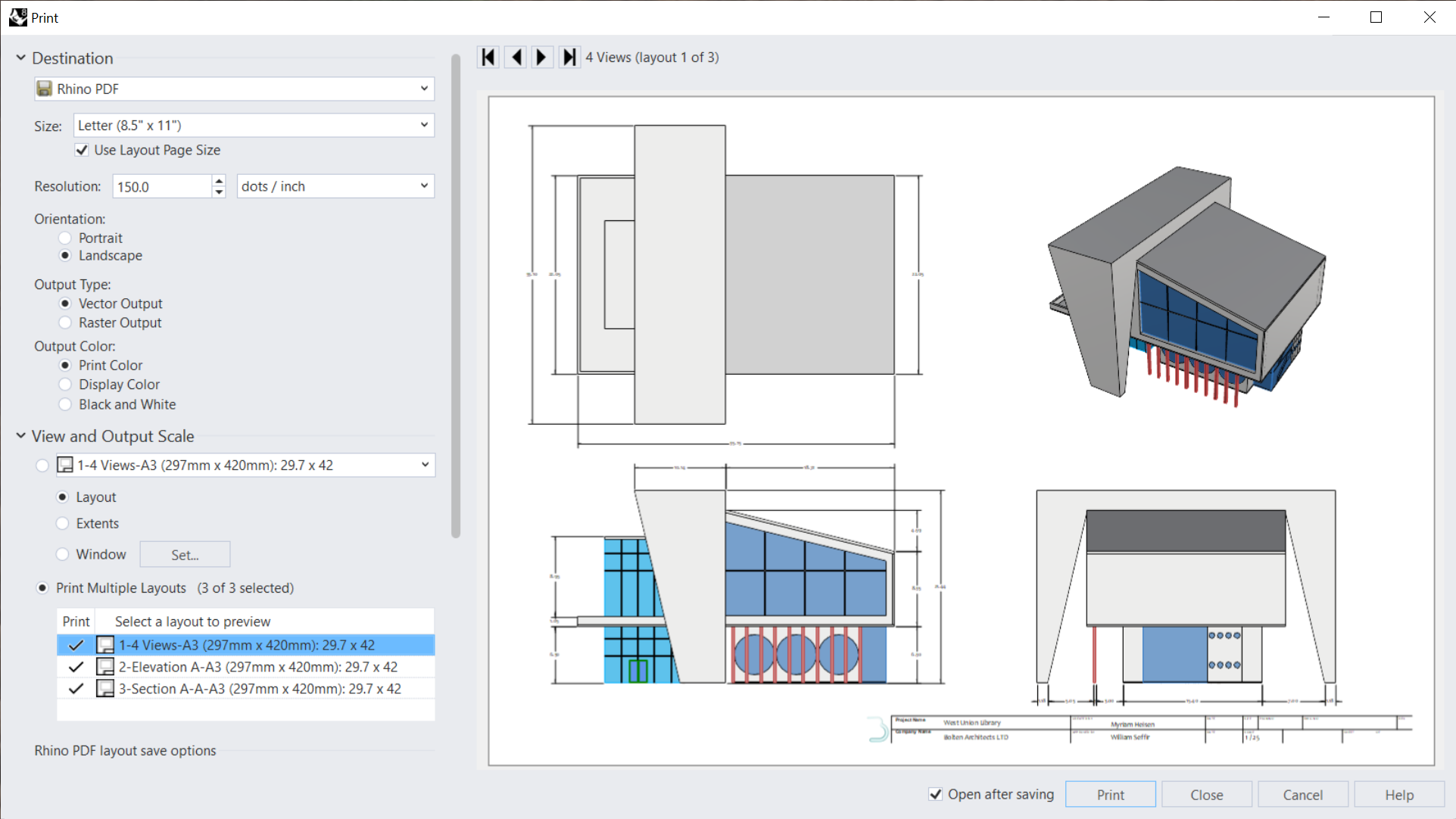
Print the Drawings
Now that we have created all our Layouts, the next step is to print them. We can print by using a physical printer or by printing to PDF, keeping the drawings in a shareable digital format. For the purpose of this exercise, we will use the latter.
- Open the xxx file
- Run the
 Layouts
command to open the panel.
Layouts
command to open the panel. - Right-click on the 4 Views layout.
- Select Print….
- In the Print dialog:
- Under Destination
- Select the RhinoPDF printer.
- For Size, select Use Layout Page Size.
- For Orientation, select Landscape.
- For Output Type, select Vector Output.
- For Output Color, seclect Print Color.
- Under View and Output Scale
- Select Multiple Layouts and tick all 3 boxes.
- Select Multiple Layouts and tick all 3 boxes.
- Under Destination
- Take a look under Margins, Linetypes or Visibility, in case you wish to modify other print settings.
- Press the button.
- In the Export PDF dialog, select a destination folder. Press the button.
NOTE TO SELF!!! To Do:
- Visualization / Diagram Archi section?!!
- Print section
- Run the
Dim
again.
- Add the dimension to the vertical side of the object.
- Run the
 DimRadius
command.
DimRadius
command. - At the Select curve for radius dimension prompt , select the top-left hole edge.
- At the Dimension location prompt , click somewhere in the upper-left corner of the view.
_______________________________________-
NOTE to Self: in case I want to add Angled and Radial Dims section back:
Add Angled and Radial Dimensions
- Stay in the Right Detail view.
- Run the
 DimAngle
command.
DimAngle
command. - At the Select arc or first line prompt , select the slanted edge of the concrete structure.
- At the Select second line prompt , select the outer edge of the concrete structure.
- For the Dimension location, drag the mouse above the structure and click. Then press .
- Run the
DimRadius
command.
- At the Select curve for radius dimension prompt , select one of the round windows. It will be the surface edge if prompted by the Selection Menu.
- For the Dimension location, drag the mouse to the left and click. Then press .
