Before learning individual tools, we will get acquainted with the Rhino interface. The following exercises examine the interface elements used in Rhino: the Rhino window, viewports, menus, toolbars, panels and dialog boxes.
The Rhino window
Rhino divides its screen into areas that supply information or prompt you for input.
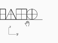
The image below illustrates some of the major features of the Rhino window.
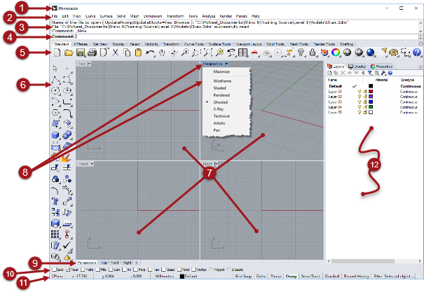
 Window title
Displays the current model’s file name and file size.
 Menu
Menu
Groups Rhino commands by function.
 Command window
Displays the previous commands. Text from this area can be copied and pasted into the command-line prompt, macro editor, button command, or any application that accepts text. You can dock the command window at the top or the bottom of the screen or it can float anywhere.
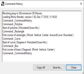
The **Command window **shows two lines by default. To open a a separate window that displays the command history, press F2. You can select and copy text in the **Command History **window to the Clipboard.
 Command prompt
Use the command-line to type commands, click command options, type coordinates, type distances, angles, or radii, type shortcuts, and view command prompts.
To enter information typed at the command-line, press Enter, Spacebar, or right-mouse click over a viewport.
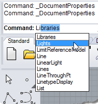
Autocomplete command name
Type the first letter of a command name to activate the autocomplete command list. As you type letters in the command-line, the command name that includes those letters will autocomplete and display in a drop down menu. Press Enter to activate the command once the full command name appears or left-click on the command in the list to start it.
Command options
Command options change how a command acts. For example, when you draw a circle, the circle is normally drawn on the active construction plane. The Circle command has several options including Vertical and AroundCurve.
To use a command option, click the option name, or type the underlined letter of the option or the whole option name.
Choose a command option
-
Type Circle
As soon as you have typed enough letters to uniquely identify the command, the **Circle **command automatically completes at the prompt. -
Press the Enter key or click the command name in the list.
-
The options for the Circle command appear:
**Center of circle: **Deformable, Vertical, 2Point, 3Point, Tangent, AroundCurve, FitPoints
- To draw a circle vertical to the active construction plane, use the Vertical option.
Click Vertical, or type V.
Repeat the last command
Many tasks in Rhino are repetitive. You might want to move or copy several objects, for example. Methods for repeating commands are provided.
To repeat the last command
- Press the Enter key when no command is active.
- In addition to pressing the Enter key on your keyboard, you can press the Space bar or click the right mouse button in a viewport.
These all perform the same function.
Note:
- Some commands, such as Undo and Delete do not repeat. Instead, the command prior to these commands is repeated. This prevents you from accidentally undoing too many commands or deleting objects accidentally.
- You can define the list of commands that do not repeat.
- For example, you may want to repeat the command that you were using before undoing a mistake with the **Undo **command. For this reason, **Undo **can be added to the list of commands that never repeats.
- Commands that you do not want to repeat are added to the text box under **Never repeat these commands **in **Options **on the **General **page.
Use recent commands
- Right-click
 the command-line to view recently used commands.
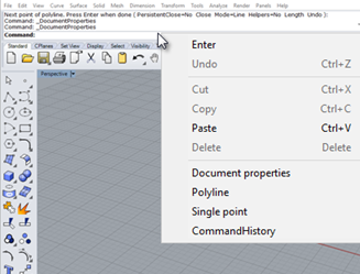
- To repeat the command, select it from the pop-up menu.
The number of commands listed is set in Rhino Options. The default limit is twenty commands. When you use your twenty-first command the first one drops off the list.
Cancel a command
To cancel a command, press Esc or enter a new command from a button or a menu.
 Toolbar group
A collection of tabbed toolbars.
 Toolbar (Sidebar)
Contain graphical icons for initiating commands.
Rhino toolbars contain buttons that provide shortcuts to commands. You can float a toolbar anywhere on the screen, or dock it at the edge of the graphics area.
Rhino starts up with the **Standard **toolbar group docked above the graphics area and the **Main **toolbar as the sidebar on the left.
Tooltips
Tooltips tell what each button does. Move your pointer over a button without clicking it. A small tag with the name of the command appears. In Rhino, many buttons can execute two commands. The tooltips indicate which buttons have dual functions.
For example:
 To access the command on the top line
- Click the icon with the left mouse button.
 To access the command on the bottom line
- Click the toolbar button with the right mouse button.
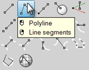
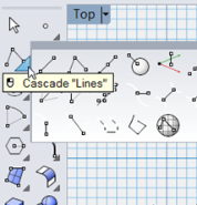
Cascading toolbars
A button on a toolbar may include other command buttons in a cascading toolbar. Usually the cascading toolbar contains variations on the base command.
Buttons with cascading toolbars are marked with a triangle in the lower right corner. To open the cascading toolbar, hover over the triangle and click. The tooltip [ Cascade “xxx”] appears.
For example, the Lines toolbar is linked to the Main sidebar. After the cascading toolbar is open, you can click any of the buttons on the toolbar to start a command.
 Viewports
The Rhino graphics area includes the viewports. You can customize number and position of the viewports.
Displays the Rhino working environment including object display, viewport title, background, construction plane grid, world axis icon.
Viewports are windows in the graphics area that show you views of your model. To move and re-size viewports, drag the viewport title or borders. From the viewport title menu, you can create new viewports, rename viewports, and use predefined viewport configurations.
 Viewport title and menu
The viewport title appears in the upper left corner of each viewport.
The viewport title offers a shortcut for viewport actions:
| | Click the title to make the viewport current. |
| | Double-click the title to maximize the viewport or to return it to its previous size. |
| | Right-click the menu to display the viewport title menu. |
| |
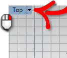
You can also click the down arrow on the viewport title to display the menu.
|
 Viewport tabs
You can also display the viewport titles in tabs. The highlighted tab designates the active viewport. Tabs make it easy to switch between viewports when using maximized or floating viewports.
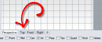
The tabs are located below the graphics area.
 Osnap control
Contains persistent object snap toggles.
 Status Bar
Displays the current coordinate system, the current location and delta of the cursor, and the Status Bar panes.
The Status Bar is located at the bottom of the Rhino window.
Tip: If the Status Bar is not visible, press Alt key. The Alt key toggles the visibility of the status bar.
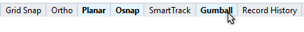
| CPlane | x | y | z | Inches |  Layer | Grid Snap | Ortho | Planar | Osnap | SmartTrack | Gumball | Record History | Filter | Info |
Status Bar options
| CPlane/World | The construction plane/world coordinates toggle. | | x | The mouse cursor x location. | | y | The mouse cursor y location. | | z | The mouse cursor z location. | | Units/Delta |
The current units setting.
During drawing commands, displays the distance from last picked point to the current location.
| | Layer | If objects are selected, the Layer pane displays the layer of the selected objects.
If no objects are selected, the Layer pane displays the current layer.
Click the Layer pane to access quick controls for setting the selected objects’ layer or to change layer visibility and status.
| | Grid Snap | Click the Grid****Snap pane to toggle Grid Snap. | | Ortho | Click the Ortho pane to toggle **Ortho **mode. | | Planar | Click the Planar pane to toggle **Planar **mode. | | Osnap | The Osnap control lets you select which object snaps are currently in effect.
Click the **Osnap **pane to toggle the display of the Osnap control.
|
| SmartTrack | Click the **SmartTrack **pane to toggle **SmartTrack **mode.
|
| Gumball | Click the Gumball pane to toggle auto **Gumball **mode. |
| Record History | Click the Record History pane to toggle history recording on/off state. |
| Filter | Click the Filter pane to open the Selection Filter control. |
| Info | Click the Info pane to display information about the current Rhino session. The **Info **pane cycles through the list of specified categories. |
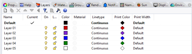
 Panels
Many Rhino controls are contained in tabbed panels. The panels are docked to the right side of the Rhino screen by default. However, they can be dragged and floated anywhere.
Open panels
- On the Panels menu, click the name of the panel you want to open.
Or
Right-clicka panel tab.
Panels that you will work with in Level 1 training are:
- Display
- Layers
- Help
- Named CPlanes
- Notes
- Properties
- Web browser
Note: Positioning the mouse over the tabs allows the mouse wheel to scroll through the tabs.
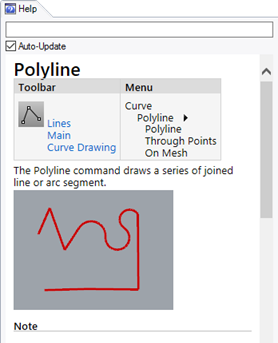
Help and Help panel
Press F1 at any time to access Rhino Help. In addition to finding information about each command, Rhino help has conceptual information as well as many examples and graphics to help you complete your model. When you are confused or unsure about what to do, the first place you should look is the help file. You can also access help for a specific command by starting the command and press F1.
In addition, the CommandHelp command displays the help topics in the **Help **panel and displays help for the current command.
Most of the commands include short video clips that show how the command and the options work.
If Auto-Update is checked, the help for the current command displays. If Auto-Update is unchecked, you can type the name of the command that you want displayed and press Enter to display the information.
The **Help **panel gives location of command on the Menus and Toolbars. For example, you can type a command, and the **Help **panel will detail where the commands are found.
Help panel.
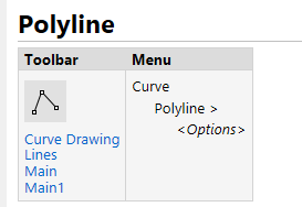
Command Finder
Note:
In this training guide, the commands are located for you primarily in the menu.
As you gain experience and prefer to use the toolbars, the **Help **panel will locate the commands for you.
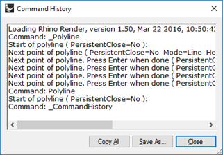
Command-line history
The **Command History **window lists the last 500 command lines from the current Rhino session.
Press F2 to view the command history.
Mouse actions
Pick
In a Rhino viewport, the left mouse buttonselects objects and picks locations.
In this training guide, *Pick *and *click *are used interchangeably in this guide to communicate a left mouse button pick.
Three button mouse
The right mouse button has several functions including panning and zooming, popping up a context-sensitive menu, and acting the same as pressing the Enter key.
- Use the left mouse button to select objects in the model, commands or options on the menus, and buttons in the toolbars.
- Use the right mouse buttonto:\
- Complete a command\
- To move between stages of commands\
- To repeat the previous command.\
- To initiate commands from some toolbar buttons.
- Drag with the right mouse buttonto pan a parallel view.
- Drag with the right mouse button, hold down Shift key to pan a perspective viewport.
- Drag with the right mouse buttonto rotate a perspective viewport.
- Use the mouse wheel to zoom and change the magnification of the view
- With a the track pad or 2-button mouse, hold down the Ctrl key and drag with the right mouse button to zoom a viewport.
You must press and hold the right mouse button down to activate this feature.
Note: If you have selected your primary mouse button to be the right mouse button in your operating system’s mouse configuration, then use the right as a the Pick.
Exercise 3-2 Getting started
-
On the File menu, click Open.
-
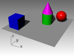
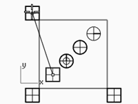
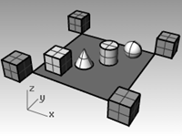
In the Open dialog box, navigate to the Level 1 folder and Open the model Start.3dm.
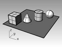
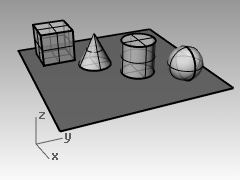
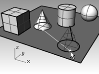
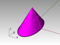
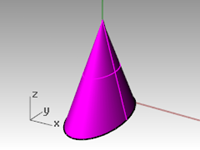
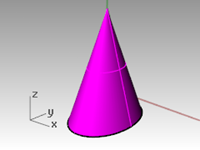
This model contains five objects: a cube, a cone, a cylinder, a sphere, and a rectangular plane.
It opens in a three viewport configuration: it opens in two parallel viewports and one perspective viewport. -
On the View menu, click Viewport Layout, and then click 4 Viewports.
The result is three parallel viewports and one perspective viewport.
**Note: **To return to the three viewports, on the View menu, click Viewport Layout, and then click 3 Viewports. -
On the Status Bar, click Grid Snap to turn on the Grid Snap.
Grid Snap may already be on in your system. Be careful that you do not turn it off instead of on. If Grid Snap is on, it will be bold and black on the Status Bar. If it is off, the word it will be gray.

Note: This is an important step. Grid Snap only lets your cursor move in certain intervals. In this model, the setting for Grid Snap is one-half of a grid line. Grid Snap helps you line up your objects as if you were building with LEGO® blocks.
Activate a viewport
- Click in the Perspective viewport to make it active.
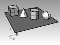
The viewport title highlights when it is active. The active viewport is the viewport where all your commands and actions take place. - Click the arrow icon on the Perspective viewport title or right-mouse click the viewport title to display the viewport menu, and then click Shaded.
The objects appear shaded. A shaded viewport lets you preview the shapes. The viewport will remain shaded until you change it back to a wireframe view.
You can change any viewport to the **Shaded **display mode.

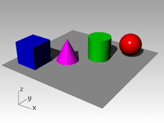
Render the viewport
- On the Render menu, click Render.
Rendering the model opens a separate render window.
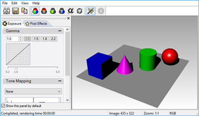
The model displays in render colors previously assigned to the objects. You can also set lights and a background color. You will learn about doing this later.
You cannot manipulate the view in the render display window but you can save image to a file. - Close the render window.
Tumble the viewport
-
In the Perspective viewport, click and drag with your right mouse button held down to rotate the view.
The plane helps you stay oriented.
-
On the Perspective viewport title menu, click X‑Ray.
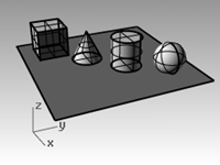
-
On the Perspective viewport title menu, click Ghosted.
-
On the Perspective viewport title menu, click Rendered.
-
On the Perspective viewport title menu, try Technical, Artistic, and Pen display modes.
-
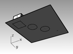
To rotate your view, drag from the bottom of the view toward the top.
You are now under the objects looking up.
The plane obscures the objects. In the **Shaded **display mode, the plane helps you see when your viewpoint is below the objects.
| The **Technical **display mode displays lines as though the drawing were a 2-D, flat drawing on paper.
This mode uses realtime silhouettes and intersections, creases, borders, blended shaded and rendered display. Objects behind other objects appear occluded. | 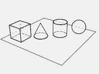 |
| The **Artistic **display mode is similar to **Technical **mode. **Artistic **mode displays lines as though the drawing were a 2-D, flat, pencil drawing on textured paper. |
|
| The **Artistic **display mode is similar to **Technical **mode. **Artistic **mode displays lines as though the drawing were a 2-D, flat, pencil drawing on textured paper. | 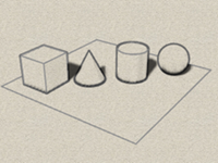 |
| **Pen **display mode is similar to **Technical **mode. **Pen **mode displays lines as though the drawing were a 2-D, flat, pen drawing on paper. |
|
| **Pen **display mode is similar to **Technical **mode. **Pen **mode displays lines as though the drawing were a 2-D, flat, pen drawing on paper. | 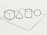 |
|
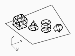
- Change to Wireframe mode.
Navigating the model
You have used the right mouse buttonto rotate in the **Perspective **viewport. You can hold Shift and drag with the right mouse buttonto pan. Dragging the right mouse buttonto move around does not interrupt any commands in progress.
Pan in a viewport
-
In the Perspective viewport, hold the Shift and drag with the right mouse button to pan the view.
-
Pan the view in the parallel viewports by dragging with the right mouse button.
The Top, Front, and **Right **viewports use a parallel projection.
In the parallel viewports, it is not necessary to press the Shift key. -
Pan the viewport using the Shift key and the right mouse button.
-
Pan the viewport in a parallel view with the right mouse button.
Zoom in and out
Sometimes you want to get closer to your objects or move back so you can see more. This is zooming. As with many things in Rhino, there are several ways to do this. The easiest way is to roll the mouse wheel to zoom in and out. If you do not have a wheel mouse, hold down the Ctrl key and drag up and down in a viewport with the right mouse button.
Zoom in and out
-
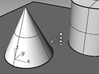
In the Perspective viewport, roll the wheel on your mouse forward to zoom in, roll it backward to zoom out.
The camera zooms at cursor position. -
In the Perspective viewport, hold the Ctrl key, click, hold the right mouse button, and drag the mouse up and down.
-
Drag up to zoom in.
-
Drag down to zoom out.
-
Zoom the viewport using the Ctrl key and the right mouse button.
Zoom extents
The Zoom command, Extents option displays a viewport so the objects fill up the viewport as much as possible. You can use this command to make everything visible.
Zoom extents in a viewport
- On the View menu, click Zoom, and then click Zoom Extents.
If you get lost, it is often handy to zoom extents in all your viewports at once, so there is a command to do just that.
Zoom extents in all viewports
- On the View menu, click Zoom, and then click Zoom Extents All.
Move objects
Dragging follows the construction plane of the current viewport.
Move objects
-
If Gumball is on bold in the Status Bar, gumball is on.
-
Click to turn gumball off.
-
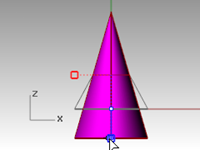
Click the cone and drag it.
-
Drag the objects around. You can drag in any viewport.
In this model, the Grid Snap setting is one-half of a grid line. Using this snap, you should be able to line objects up with each other.
The selected cone changes to the selection color.
-
Drag the cone in the Perspective viewport until it lines up with the cylinder.
It will be inside the cylinder.
The cone moves on the base represented by the grid. This base is a construction plane. Each viewport has its own construction plane. When you start Rhino, the **Perspective **viewport has the same construction plane as the Top viewport. You will learn more about using construction planes later. -
From Edit menu, click Undo.
-
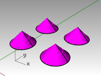
Drag the cone in the Perspective viewport until it lines up with the cylinder. Next tap the Alt key.
You will see a plus + on the screen. Pick a location and the cone is copied to base surface.
-
From Edit menu, click Undo.
-
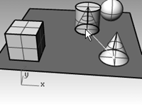
In the Front viewport, drag a cone to the top of the cylinder.
Watch what happens in the Perspective viewport.
Watch the other viewports to place your objects.
-
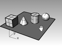
Click in the Perspective viewport.
-
Change the viewport to a Rendered display.
Copy objects
To create more objects, copy the shapes.
Open the model
- On the File menu, click Open.
- Do not save the changes.
- In the Open dialog box, select Start.3dm.
Copy objects
- Click the box to select it.
- On the Transform menu, click Copy.
- Click somewhere in the Top viewport.
It usually helps to click a spot that relates to the object like the middle or near a corner.
- Click where you want the first copy.
Zoom in closer if you like. - Click other places to make more copies of the box.
- When you have enough copies, press Enter.
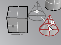
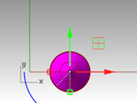
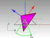
Editing with gumball
Gumball displays a widget on a selected object, which is used to facilitate the direct editing. The gumball provides move, scale, and rotate transformations around the gumball origin.
- Click the **Gumball **pane on the Status Bar.
Gumball actions
- Drag gumball arrows to Move the object.
- Drag scale handles (squares) to Scale the object in one direction.
- Drag arcs to rotate the object.
- Tap the Alt key after starting to drag to toggle copy mode.
- Click a control handle to enter a numeric value.
- Hold the Shift key during Scale to force 3-D scale.
|
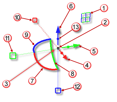
Gumball Controls
 Axis plane indicator
 Free move origin
 Menu location
Move arrows
 Move X
 Move Y
 Move Z
Rotation arcs
 Rotate X
 Rotate Y
 Rotate Z
Scale handles
 Scale X
 Scale Y
 Scale Z
 Extrude Z
|
|
Move geometry with the gumball
-
In the Top viewport, select the cone.
-
Drag the red arrow to move the object in the positive x or negative x-direction.
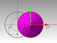
-
Drag the green arrow to move the object in the positive y or negative y-direction.
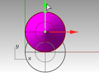
-
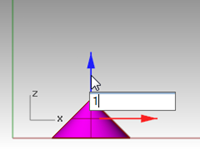
In the Front viewport, select the cone.
-
Drag the **blue arrow **to move the object in the positive z or negative z-direction.
-
Undo enough times to get back to the original model.
-
In the Top viewport, select the cone.
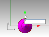
-
Click x Move Arrow (red) to enter numeric value of 1.
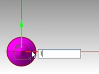
The cone moves a distance of 1 units to the right.
-
Repeat for y Move Arrow and z Move Arrow.
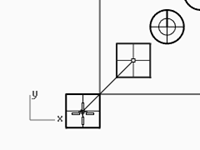
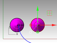
Copy objects with gumball
In this exercise you will drag objects with the gumball and tap the Alt key after starting to drag to toggle copy mode.
- In the Top viewport, select the cone.
- Drag the red arrow to move the object in the positive x or negative x direction.
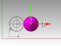
- While still dragging, tap the Alt key.
A plus + appears to the right of the red arrow.
When you release the mouse button, a copy of the object is created.
- In the Top viewport, select the two cones.
- Drag the green arrow to move the objects in the positive y direction.
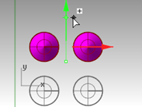
- While still dragging, tap the Alt key.
A plus appear to the right of the green arrow.
When you release the mouse button, a copy of the object is created. - Undo enough times to get back to the original model.
Rotate objects with gumball
Drag arcs to rotate the object.
- In the Top viewport, select the cone.
- Click and drag along blue arc to rotate cone.
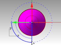
- In the Right viewport, click and drag along green arc to rotate cone.
- Undo enough times to get back to the original model.
Scaling with Gumball
- Drag scale handles (squares) to Scale the object in one direction.
- Click a scale control handles (squares) to enter numeric value.
- Hold the Shift key during Scale to force 3-D scale.
Scale objects with gumball
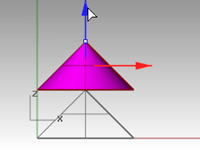
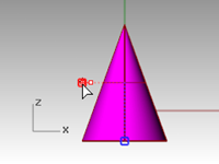
- In the Front viewport, select the cone.
- Drag the red scale handle (square) to scale the object.
Release the mouse button to complete the scale.
- In the Front viewport, select the cone.
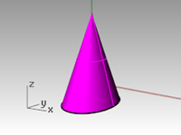
- Drag the blue scale handle (square) down to scale the object larger in height.
Release the mouse button to complete the scale.
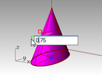
- Try clicking a scale control handle (square) and enter numeric value or scale factor like .75.
- In the Front viewport, select the cone.
- While holding down the Shift key, drag the red scale handle (square) to scale the object uniformly in the x, y, and z direction. Let go to complete the scale.
- Undo enough times to get back to the original model.
Try on your own
- Make copies of more objects and move them around.
See if you can build something.
Change the view of your model
When you add detail to your models, you will need to see different parts of your model with different magnifications. You can use the view commands, the mouse, and the keyboard to change the view in a viewport.
Each view corresponds to the view through a camera lens. The invisible target of the camera is located in the middle of the viewport.
Viewports
With Rhino, you can open an unlimited number of viewports. Each viewport has its own projection, view, construction plane, and grid. If a command is active, a viewport becomes active when you move the mouse over it. If a command is not active, you must click in the viewport to activate it.
Most viewport controls can be accessed through the viewport pop-up menu.
To open the pop-up menu, right-clickthe viewport title.
Or click the small triangle on the viewport title.
Parallel vs. perspective projection
Unlike other modelers, Rhino lets you work in both parallel and perspective views.
Toggle between parallel and perspective views
- Right-clickon the viewport title, and on the menu, click Viewport Properties.
- In the Viewport Properties dialog box, for Projection click Parallel or Perspective, and then click OK.
Pan and zoom
The simplest way to change the view is to hold down the Shift key and drag the mouse with right mouse button held down. This pans the view. To zoom in and out, hold down the Ctrl key and drag up and down or use the mouse wheel.
You can also use the keyboard to navigate:
| Perspective Projection | Parallel Projection | |
|---|---|---|
| Key | Action | Action + Ctrl |
| — | — | — |
| Left arrow | Rotate left | Pan left |
| Right arrow | Rotate right | Pan right |
| Up arrow | Rotate up | Pan up |
| Down arrow | Rotate down | Pan down |
| Page Up | Zoom in | |
| Page Down | Zoom out | |
| Home | Undo view change | |
| End | Redo view change |
You can change your view in the middle of a command to see precisely where you want to select an object or select a point.
There are additional zoom controls that will be discussed in other exercises.
Reset the view
If you get lost, four view techniques can help you get back to a starting place.
Undo and redo view changes
- Click in a viewport, press your Home or End key on your keyboard to undo and redo view changes.
Set the view looking straight down on the construction plane
- On the View menu, click Set View, and then click Plan.
Bring all your objects into view
- On the View menu, click Zoom, and then click Zoom Extents.
Bring all your objects into view in all viewports
- On the View menu, click Zoom, and then click Zoom Extents All.
Display options
Exercise 3-3 Practice with Display Options
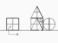
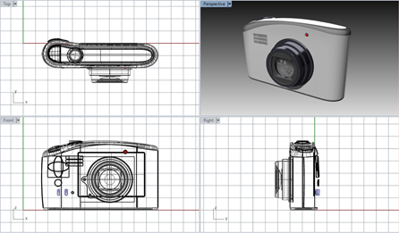
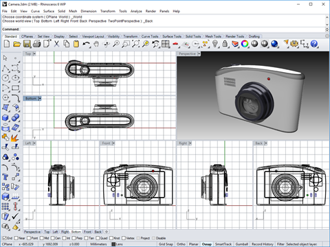
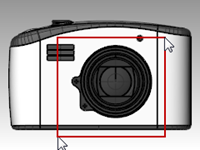
You will use the camera model to practice changing views. You will create views from six directions and an oblique perspective view.
-
Open the model Camera.3dm.
-
Click in the Top viewport to make it active.
-
On the View menu, click Viewport Layout, and then click Split Horizontal.
-
Make the Front viewport active.
-
On the View menu, click Viewport Layout, and then click Split Vertical.
-
Repeat this step for the Right viewport.
-
Right-click
the Top viewport title, click Set View, and then click Bottom.
Three viewports are split down the middle either horizontally or vertically.
Change the shape of viewports
- Move your cursor to the edge of a viewport until you see the resizing or cursor, hold the left mouse button down, and drag the bar.
- Move your cursor to the corner of a viewport until you see the resizing cursor, hold the left mouse, and drag the intersection in any direction. If several viewports touch at that corner, all re-size.
Synchronize the viewports
- On the View menu, click Zoom, and then click Zoom Extents.
- On the Front viewport title, click Set Camera, and then click Synchronize Views.
All the parallel views are sized to the same scale as the active viewport and aligned with each other. - Change the viewport displays to one of the shaded viewport settings.
- On the Front viewport title on the left viewport, click Set View, then click Left.
- On the Right viewport title on the right viewport, click Set View, then click Back.
Zoom to a window
- On the View menu, click Zoom, and then click Zoom Window.
- Click and drag a window around a portion of the model.
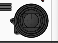
Zoom to a selected object
- Select the shutter release.
- On the View menu, click Zoom, and then click Zoom Selected.
The view zooms to the selected object.
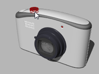
Rotate the view
- In a perspective viewport, drag with right mouse button.
- In a parallel viewport, on the View menu, click Rotate or use Ctrl+Shift and drag with the right mouse button.
Maximize and restore a viewport
- Double-click the viewport title to maximize the viewport.
- Double-click the title of the maximized viewport to restore the viewport to its smaller size and reveal the other viewports.
Start drawing
The Line, Lines, and Polyline commands draw straight lines. The **Line **command draws a single line segment. The **Lines **command draws multiple end-to-end line segments. The **Polyline **command draws a series of straight or arc joined segments (a single linear curve with multiple segments). To Rhino, all these lines are curve geometry.
Exercise 3-4 Draw lines
- On the File menu, click New. Do not save changes.
- In the Template File dialog box, double click Small Object - Millimeters.
- On the File menu, click Save As.
- In the Save dialog box, type Lines, and then click Save.
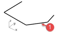
Draw line segments
- On the Curve menu, click Line, and then click Line Segments.
- Pick a point in the **Top **viewport.
- Pick another point in a viewport.
A line segment appears between the two points. - Continue to pick points.
Additional segments appear. - Press Enter to end the command.
The segments meet at a common point, but are not joined.
Close option
The Close option closes the shape by drawing a segment from the last point picked to the first point picked. It applies to many curve drawing commands.
Use the Close option
- Repeat the Lines command.
(Choose from the menu again or right-click in the viewport.) - Pick a Start point and 3 or 4 more points.
- In the command-line, click Close.
The last line segment will end at the original start.
Draw a polyline
- On the Edit menu, click Undo.
Or press Ctrl + Z. - On the Curve menu, click Polyline, and then click Polyline.
- Pick a Start point and 3 or 4 more points.
- Press Enter when done.
This makes an open polyline. A polyline a single object made of line segments that are joined together.
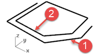
Use the Undo option
The Undo option deletes the last point picked.
Use the Undo option
-
Repeat the Polyline command.
-
Pick a Start point and 3 or 4 more points.
-
In the command-line, click Undo.
Notice that your cursor moves back to the previous point and one segment of the polyline is removed. -
Continue to pick points.
-
Click Close to end the command.
This makes a closed polyline (2).
Draw a single line segment
- On the Curve menu, click Line, and then click Single Line.
- Pick a Start point.
- Pick an End point (3).
The command ends after one segment is drawn.
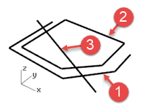
Use the Bothsides option
- On the Curve menu, click Line, and then click Single Line.
- Click Bothsides in the command-line.
- Pick a Middle point.
- Pick an End point (4).
A segment is drawn with equal length on both sides of the middle point.
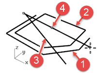
Free-form curves
The InterpCrv and Curve commands draw free-form curves. The InterpCrv command draws a curve through the points you pick. The Curve command uses control points to create a curve.
Draw interpolated curves
- On the Curve menu, click Free-form, and then click Interpolate Points.
- Pick a Start point.
- Continue picking points.
Notice that with this command the curve goes through each point that you pick (5).
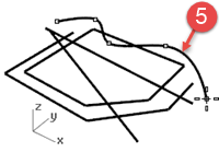
- Press Enter to end the command.
This makes an open curve.
Draw curves from control points
-
On the Curve menu, click Free-form, and then click Control Points.
-
Pick a Start point.
-
Continue picking points (6).
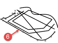
The points you pick are control points and may not lie on the curve. -
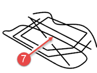
Click Close to make a closed curve (7).
Save your work
Save your work periodically during a session to keep it from being accidentally deleted.
Save your model
- On the File menu, click Save.
Or
Click one of the other options.
You will have an opportunity to save your work.
It is good practice to save your model in stages under different names, using the **Save As **command. This lets you go back to an earlier version of your model for modifications if necessary.
