A common question Rhino users ask when presented with a complex modeling task is “Where do I start?” While there are often multiple approaches to modeling problems, start by first developing a general guideline or methodical approach. This will make modeling efficient and avoid timely remodeling tasks.
In other words, consider the shapes that need to be built and spend some time working out a strategy for laying out the surfaces that you’ll need. It is helpful to try to separate the main or ‘primary’ shapes from transition shapes or ‘secondary’ such as fillets and blends. A surface should not be both a primary and secondary surface, as a general rule.
If you keep the primary surfaces as simple and clean as possible, maintaining surface fairness is much easier and adding transition surfaces can be a simpler task as well.
The Cutout
This type of advanced surface models is not limited to any one industry. The cutout techniques can be applied to a car hood, bike helmet, a boat vent, a roof or any model that needs a cutout surface with a smooth transition back to the main surface.
Exercise 9-1 Set up and build from the “floor” surface
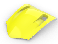
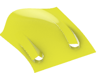
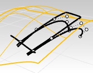
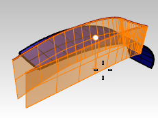
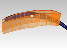
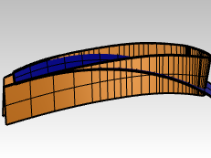
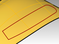
The modeling goal in this exercise is to build a cutout or scoop in a surface which integrates seamlessly and naturally with the surface. You will start with the existing surface and some 2-D curves that define the shape we’re shooting for - and you will build some reference curves and some simple primary surfaces that have good continuity where required. In final steps, you will work on getting the transition surfaces in place with the required continuity.
Open and prepare the model
-
Open the model Scoop.3dm.
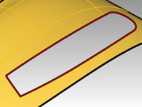
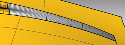
You will see a version of the desired result as the file opens - this is what we’re shooting for. -
Select the Cut-out curves layer in the layer panel, right click and choose One layer on.
This will set the ‘Cut-out curvesas current and turn off the others. -
In the Layer panel make the following changes to the layers: sai
| Layer | State | | Cut-out curves | on and current | | All other layers | on | | Completed Scoop | off |
Project and extend the curves
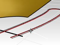
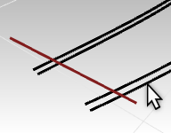
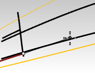
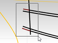
Next, you will set up some reference curves on the surface. The floor of the scoop will be ‘overbuilt’, that is, made larger than you need it, is trimmed back to the size and shape later. This allows us to make the surfaces very simple and rectangular without being too concerned at this point about the exact shape of the edges.
-
In the **Top **viewport, select the outside curve. The Cut-out curves layer should be on and current.
-
Click **Curve **menu, Offset and Offset Curve.
-
Set the Distance to 5 and offset the curve to the outside.
-
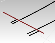
Use the line to trim off the loop part of the offset, leaving two short curves next to the line.
-
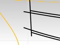
Select the line and the trimmed curves only.
-
Start the Project command (Curve menu: Curve From Objects > Project).
-
Select the surface and press Enter.
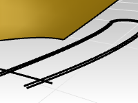
The curves will be projected onto the surface.
The projected curves will help us to set up the curves that define the floor of the scoop.
Creating the side walls
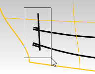
In order to create the side walls of the scoop, you can extrude the shape downward from the surface but we’ll need to get that shape curve up onto the surface first. You will use the **Project **command as you did with the curves in the previous step.
Keep in mind that the**Project **command uses the tolerance settings. (For more information on tolerances, see this page.)
Projected curves are generally more complex than the originals. It is a best to keep the curve simple as possible. To accomplish this, you will use the **Loose **option in the **Project **command.
-
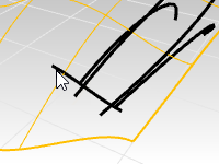
In the **Top **viewport, select the 2D scoop shape curve.
-
Start the **Project **command.(Curve menu: Curve From Objects > Project).
-
Before clicking on the surface as the target, set the command-line option to Loose=Yes.
-
Next select the target surface and Enter to finish the command.
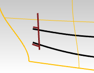
If you turn on control points for this projected curve, you will see that it has the same control point structure as the original 2D curve. Note that using the Loose option results in a curve that is not necessarily within tolerance of the target surface. In many cases, as in this one, it will be close enough and a little simpler and cleaner, which is a good thing when using the curve as an input to a surface.
-
Lock original curves on Top construction plane so they will be available for visual reference but will not be selected accidentally. This will be more easily done in the **Front **view with a window select.
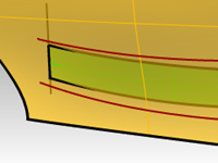
Make the curves for the floor of the scoop
Next, you will make a surface for the bottom or “floor” of the cutout.
The cutout is rounded at one end, but you will build a rectangular surface and trim it to be round at one end.
This approach allows for a much lighter, more easily controlled surface than trying hitting the edges exactly while building the surface.
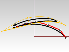
First, you will make one curve with as few points as possible that best represents the shape of the part that will become the bottom of the scoop.
When making the curve, try to look at it from various views while you work.
Use the **Curve **command and set the command-line option **degree=5 **. Use no more than six control points for a very smooth curve.
You will also check the curve with the curvature graph to get a very fair curve.
-
Open Scoop 001.3dm if needed. Otherwise, keep working in the scoop model from the previous section.
-
On the Status Bar, turn Planar mode on.
This will keep the curve in a single plane for the moment. -
With the **Front **viewport active, from the **Curve **menu, click **Freeform **and Control Points.
-
On the command-line, set the **Curve **command options to Degree=5.
-
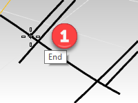
Snap to the end of one of the short projected curves in any convenient view.
-
Set the second point just approximately in the tangent direction to the short projected curve with which you started.
Note: You do not need to get point locations perfect the first time. You will control point edit the curve to get the exact shape soon.
-
Switch to the Front viewport to continue drawing. Then place the next four points in a smooth and evenly spaced arrangement.
-
Adjust the control points as needed using the **CurvatureGraph **command to make a smooth progressive curve. You want the curvature to increase smoothly as the curve dives down.
-
Adjust the curve with point editing to get the right shape in the **Top **viewport.
Make sure to move the points only in the y‑direction (Ortho will help), so that the shape in the Front viewport will not be altered.
Note: The **Gumball **is recommended over dragging for moving the point. Make sure Gumball is set to align to CPlane or World (**Gumball context **menu).
-
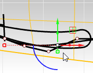
In the **Top **view, select the last three points on the curve. Slide them using the **Gumball **green arrow, in the Y direction. This ensures that the shape as seen from Front will not be changed.
-
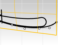
Make the curve roughly parallel to the scoop shape curve in the **Top **view. Edit the control points until the curve approximates the outermost of the original curves and extend somewhat past the rounded end.
-
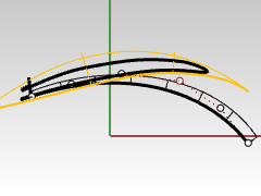
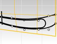
When this curve looks good, Copy the curve over to the end of the other short projected curve. It will need some editing but will be a good starting point for the second curve.
Copy the curve
- Copy the curve to the other edge.
- Adjust the curve with point editing to get the right shape in the **Top **viewport.
- Use point editing, Match, CurvatureGraph and EndBulge to massage this curve in the same way as before to be clean and continuous with the projected curve, and have the same curvature character as the first curve.
##Fix the continuity
To fix the continuity, you will first make sure the new curve is matched for curvature to the little projected curve that you used as the starting point. This is really why you projected that curve onto the surface. You will match our new curve for Curvature to the projected curve which lies on the surface. This will ensure that the new curve is well aligned and matched to the surface itself. This will setup the floor surface so you can easily edit it to match to the main surface.
-
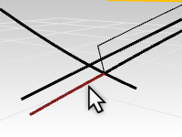
Use the Match command (Curve menu: Curve Edit Tools > Match). Select the curve you just edited.
-
Next pick the trimmed curve as the match for the Curvature continuity.
-
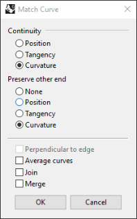
In the **Match **dialog:
**Continuity **is set to Curvature
**Preserve other end **does not matter in this case, but you can set to Curvature.
Do not check Average, **Join **or Merge.
-
Next, use Matchagain to adjust the continuity of the copied curve.
Select the curve that you just copied and edited.
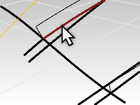
-
Next pick the trimmed curve that you copied earlier.
-
In the **Match **dialog:
**Continuity **is set to Curvature
**Preserve other end **does not matter in this case, but you can set to Curvature.
Do not check Average, **Join **or Merge.
-
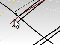
Use of the EndBulge command and further point editing may be needed.
Make any final tweaks to the curve. The previous Match operation may have made the curvature acceleration a little messy.
Keep in mind that editing the last three points on the curve is ok, but the end that you matched earlier is not an option if the goal is to maintain the curvature match. To edit these points use theEndBulge command, which constrains the point movement so that the curvature at the end is not changed. Strive for evenly spaced control points overall. -
The short projected curves can now be hidden or deleted.
If matching makes the curve distort too much add a knot and try again.
Sweep the floor surface of the scoop
Now that you have two nicely matching curves defining the overbuild for the scoop floor surface, let’s see about actually creating the surface. A couple of surfacing tools come to mind immediately - Sweep2 and Loft. Either will work nicely, you will take a look at both. Sweep2 will be covered in this section.
To use Sweep2 here, you will need two rails and at least one cross section or shape curve. So far you have two nice rails only. So how can you get a cross section curve that makes sense? The projected line is a good start but it currently extends past the rail curves, you will fix that with the **SubCrv **command.
-
From the **Curve **menu, select Curve Edit Tools and SubCrv.
-
With command options set to **Copy=No **and **Mode=Shorten **, select this curve.
-
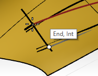
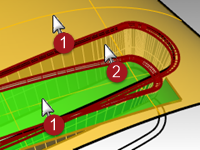
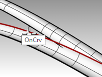
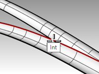
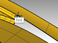
For the Start of curve, pick where the outside curve intersects the previously selected curve. Pick the point with the Int or End osnap where the rail curves hit the projected line to shorten the curve.
-
For the End point, select where the outside curve on the other side like intersects the previously selected curve. Pick the point with the Int or End osnap where the rail curves hit the projected line to shorten the curve.
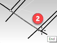
The curve is shortened to include only the portion of the curve between the two selected points on the curve. Snap to the Int or End points where the rail curves hit the projected line to shorten the curve. -
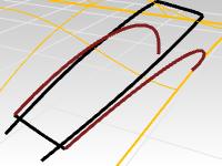
Select the two rail curves.
-
Start Sweep2. Sweep2 will use the two selected curves as the rails.
-
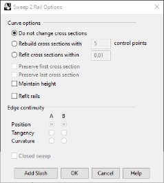
For the cross section, select the curve you just shortened as the single cross section curve.
Note: you may want to add line between the lower ends of the rail curves and include this as a cross section curve, thus forcing the sweep2 surface to fade to a straight line at the lower end. Either way will work well.
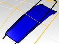
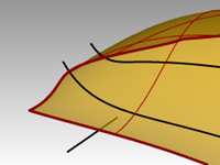
Loft a surface
Another option is to loft the two curves to create the surface. The surface will need adjustment to match to the original surface. This will provide the opportunity to explore some options in the **MatchSrf **command
While this surface has the advantage of being extremely simple and clean, as is it has no way to attach itself to the larger surface at the front edge - it is a straight surface whereas the larger surface is curved, so there is no match, we’ll need to fix that.
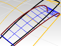
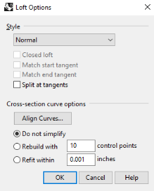
- Select the two curves and start Loft.
- Start theLoft command (Surface menu: Loft) to create the surface between the two curves.
Because the lofted surface is flat, there will be a slight gap at the edge of the original surface. Make sure the loft dialog Style is set to Normal and ‘Do not simplify’.
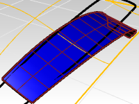
While this surface has the advantage of being extremely simple and clean, as is it has no way to attach itself to the larger surface at the front edge - it is a straight surface whereas the larger surface is curved, so there is no match. You will fix that next.
MatchSrf
Whichever surfacing tool you use, you want to be sure the new surface blends seamlessly to the larger surface.
-
Start the MatchSrf command (Surface menu: Surface Edit Tools > Match) to match the lofted surface to the edge of the original surface for curvature.
-
At the prompt to select the curve or edge to match, select the shortened line that defines the front edge of the scoop as the edge to change.
-
At the prompt to select the curve or edge to match, click the command-line option for **CurveNearSurface **to On. This will allow us to match to any curve or location on the target surface, not just an edge of that surface.
-
Enter and you will be promted to select the target surface. Select the larger original surface.
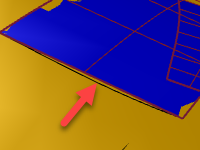
The edge of the scoop floor will be pulled down to the target surface along the curve that you selected.
The match surface with preview in the viewport.
You may notice that the matched surface pulls around quite drastically to be perpendicular to the target edge. That will be addressed that in the next step. -
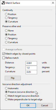
You want to match curvature by closest points and preserve the isocurve direction of the surface.
In the MatchSrf dialog change the Isocurve adjustment from Automatic to Preserve isocurve direction.
The surface should now preview to match with much less distortion.
 .
.
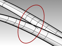
Check the continuity
To check how the previous **MatchSrf **worked, you will use the **Zebra **analysis command to visually check the continuity of the two surfaces. Because the surfaces overlap out in the middle of the target surface, you will need to set the analysis mesh for the Zebra display very fine and accurate to minimize interference between the display of the two surfaces where they come together.
-
Select the large surface and the scoop floor surface.
-
Start the Zebra command (Analyze menu: Surface > Zebra) to check the continuity of the two surfaces.

-
When the display changes to show the zebra stripes, click on the Adjust mesh button in the **Zebra **dialog. You will increase the density of the analysis mesh.
-
Set the **Maximum Distance Edge to Surface **to .01, and the **Minimum initial grid quads **to 5000. You could even go up to 10,000. Pick the Preview button to view your new mesh.
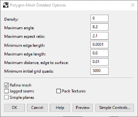
-
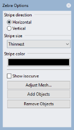
Set the stripe direction **Horizontal **and the **Stripe **size to **Thinner **to get a good display. Pick Ok.
-
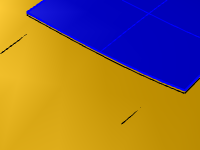
Now you can analyze the zebra stripes with the additional smoothness on the render mesh.

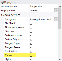
Note: it may be helpful to turn off **Curve display **in the **Display mode **panel temporarily to better see the **Zebra **display at the location of the projected line.
Be careful and don’t forget to turn Curves back on.
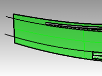
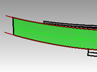
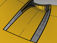
Build the sides of the cut-out
To build the sides of the cut out, you will extrude the curve downward that was projected to the original surface at the start of this exercise. You can assume the object needs to be pulled vertically from a mold, so you need to design the surface with a draft angle. You will use 10 degrees of draft and then trim the extruded surface with the lofted surface from the previous step.
Extruding the curve, tapered
-
Open Scoop 003.3dm if needed or keep working with your model.
-
If you can not located the projected curve, use the **Project **command to project the outer scope curve to the original surface.
-
Using the Hide command, hide the curves on the Top cplane.
-
In the Layer panel, make the **Sidewalls **layer current.
-
Select the projected curve.
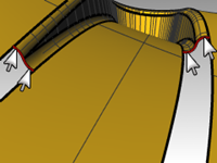
-
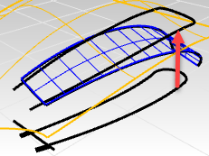
Use the ExtrudeCrvTapered command (Surface menu: Extrude curve > Tapered) to extrude the outer projected curve.
-
Set the DraftAngle to 10.
Pull the extrusion downward. With the draft angle set to 10, the extrusion should taper inward or get narrower as you pull it down. If it gets wider instead, use the **FlipAngle **option in the ExtrudeCrvTapered command to change the extrude taper. -
Pull the surface until it fully intersects with the bottom surface, stop there and pick.
If you extrude the surface too far, you might get a polysurface instead of a single surface.
Check this is the Properties panel.
If this happens try to extrude again, but do not pull so far.
If you cannot pull it far enough to penetrate the floor without making a polysurface, extrude it a short distance instead.
-
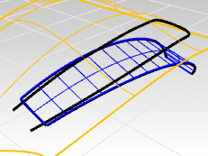
If necessary, use the ExtendSrf command (Surface menu: Extend Surface) to extend the sidewalls surface through the floor surface.
The extruded sidewall surface is a very dense surface.
Refitting the surface
-
Start FitSrf and select the tapered extrusion.
-
Start the FitSrf command (Surface menu: Surface Edit Tools > Refit to Tolerance) to simplify the surface.
-
Set the command-line options to a Fitting tolerance of 0.001 with DeleteInput=Yes, ReTrim=Yes, UDegree=3, and VDegree=3.
| 
Before
| 
After
|
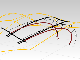
Transition surfaces
Create the fillets
First you will build constant radius ‘rolling ball’ fillets between the sides of the scoop and the floor surface that was built earlier and between the sides and the main surface that you started with.
-
Show the original surface.
-
On the Layer panel, make the Fillet layer current.
It is helpful to be in Wireframe display mode while creating and trimming the fillets. -
Start the FilletSrf command (Surface menu: Fillet Surface) with a Radius=5, Extend=No, and Trim=No to make the fillets between the bottom surface and the sides.
-
At the First surface to fillet, select the bottom floor surface.
-
Next, Select the side surface above the floor surface.
Repeat the process for the side surfaces and the main starting surface. In this case the pick location on the large surface should be outside the scoop off to one side - this will force the fillet to roll to the outside and not to the inside of the side. The fillet surfaces will be much too long and will cross each other as well - don’t worry about this, we’ll trim it all up and make it nice and neat.
Note: **FilletSrf **pays attention to where you click on the input surfaces. Since there may be up to four possible fillets between two surfaces, the pick location tells Rhino where the rails or edges of the fillets should go
The two fillets will cross each other. You will trim them both back to their intersection points.
Where you pick matters.
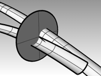
Trimming the fillet surfaces
Both of the fillet surfaces are tangent to the tapered side of the scoop. Where the fillets cross they are tangent to each other.
If you trim the ends of the fillets to a plane, then the resulting trimmed edges will be tangent to each other. Trimming these surfaces will be helpful when creating the final surfaces that blend the fillets out between the scoop and main surfaces.
To create the plane, first make circles with the AroundCurve option around one edge of the fillet surfaces, then make planar surfaces from the circles.
-
Open Scoop 004.3dm if needed.
-
Select the fillets and run the Isolate command in the Visibility toolbar to isolate them.
Every other object that is not selected and does not have control points on and is not locked, will be hidden. -
Start the Circle command, and use the AroundCurve option. Set the Intersect object snap only.
Note: Right click on Intersect in the Osnap bar. All the other osnaps will be turned off, and only the option you right clicked over, will be on.
The AroundCurve option forces the Circle command to look for curves, including edge curves, to draw the circle around.
-
Click on the upper edge of the lower surface and snap to the intersection point.
-
Draw the circle out well past the width of the fillet surfaces.
-
Start the PlanarSrf command (Surface menu: Planar Curves) and pick on the circle to create a surface with the circle curve at the intersection point.
-
Repeat these steps for the other intersection.
-
Use the Trim command and trim off the free ends of both fillet surfaces.
-
Repeat this for the ‘collision’ on the other side.
-
Delete the planar surfaces.
Trim the sides of the scoop
You can use the trimmed fillets to trim back the side surface of the scoop.
- Use ShowSelected to show the tapered side surface.
- Use the fillet surfaces as trimming objects to trim the excess from the side surface.
It is often much faster to trim with curves than to use surfaces, especially if the surfaces are tangent to the object to be trimmed, as is the case with fillets. - Duplicate the two edges that are in contact with the side surface to use as trimming objects if you have a problem.
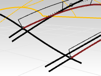
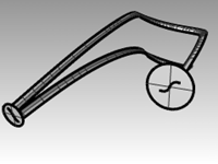
Trim the main and floor surfaces
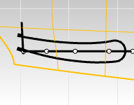
The next task is to extend the edges of the fillets so that the main surface and the floor surface can be trimmed back. The inner, or lower, edge of the lower fillet will be extended off the end of the floor surface and the outer, or upper, edge of the upper fillet will be extended off past the end of the opening of the scoop as well. The extended curves will be projected onto the respective surfaces and used to trim them.
- Open Scoop 005.3dm, if needed.
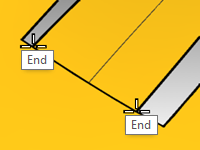
- In the Top viewport, use the Extend command with the Type=Smooth option to extend both bottom ends of the lower fillet edge past the front of the floor surface.
- Use these curves, still in the Top viewport, to Trim the outer edges from the floor surface.
- Use Extend to extend the outer edges of the upper fillet past the end of the floor surface.
Note that in the **Perspective **viewport these extended curves are off in space at their outer ends. - ShowSelected the main surface if it is hidden.
- Project the curves onto the main surface from the **Top **viewport.
- ShowSelected or turn on the layer for the original curves and Project the line segment onto the main surface.
- Trim the projected curves with one another so that they form a closed loop.
- Use the closed curves to Trim a hole in the main surface.
Set up the curves to create the surfaces
You are now nearly ready to create the surfaces. As you can see there are nice rectangular gaps in the surfaces, you just need to arrange the curves and edges surrounding the gaps for use in making a 2-Rail Sweep or a Surface from a Curve Network.
Because one end of each open rectangle is bounded by the two tangent fillet edges, you will need to create a single curve there to use as input. You will duplicate the four edges and join them into two s-shaped curves. The other end of each rectangle is bounded by a portion of the end of the hole in the main surface.
You will split up that long edge into segments that correspond exactly to the ends of the rectangular openings.
- Open Scoop 006.3dm, if needed.
- Use DupEdge to create curves at the trimmed edges of the fillets.
- Join these four edges into two curves.
- Use the SplitEdge command (Analyze menu: Edge Tools > Split Edge) and the End object snap to split the straight edge on the trimmed hole in the main surface to the end points of the floor surface’s edge.
- Use the SplitEdge command to split the long edges at the endpoints of the fillet edges.
This will help NetworkSrf find a solution more quickly.

- Use the Sweep2 command with Rail continuity=Tangency or the NetworkSrf command to create the last two surfaces.
The surfaces start with the s-shaped curves that you duplicated and end with a flat line at the split edges.
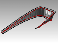
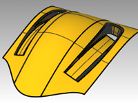
Finalize the surfaces
- Open Scoop 006.3dm, if needed.
- Join the cutout surfaces and then trim a hole at the bottom.
- Mirror and Trim to get the other scoop.
Extra cross-section curves
- Open Scoop 007.3dm, if needed.
- Use Sweep2 or NetworkSrf to close the holes.
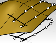
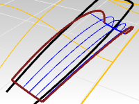
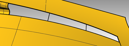
Filling the larger of the two holes may benefit from extra cross section curves.
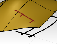
To add cross-sections, use the Blend command to make tangent curves approximately one-third and two-thirds of the way along the edges of the opening. Use these curves as additional input for a network surface.
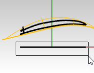
- Start the BlendCrv command (Curve menu: Blend Curves > Adjustable Curve Blend).
- At the command-line, select the Edges option.
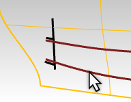
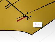
Set Continuity=Tangency. - For the Select surface edge to blend, click approximately one-third of the way along one of the long edges of the rectangular opening.
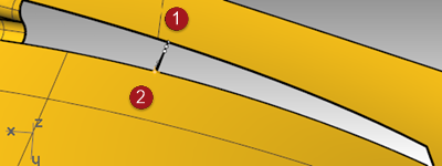
- For the other Select surface edge to blend, click on the edge opposite the first one.
The blend curve will be placed across the opening and a dialog box will open. - In the Adjust Curve Blend dialog box, set Continuity=Tangency for both ends.
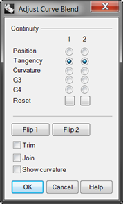
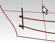
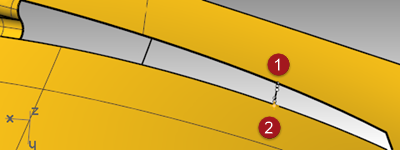
- Make a second curve the same way about two-thirds of the way along the same edges.
Note: If **BlendCrv **is used with **History **on, the curve can be adjusted later using the **Edit **command-line option in BlendCrv.
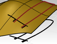
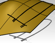
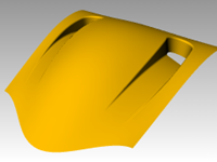
- Use the NetworkSrf command to create the surface.
Remember to include the new curves in the selection.
- Join all the surfaces into one polysurface. Assign a material and render.
