The underlying geometry of NURBS surfaces have a rectangular topology in UV, or parameter space. Rows of surface points, and parameterization, are organized in two directions (U and V). These two directions are crosswise to each other, at more or less 90 degrees on an ideal surface, though this is not always possible. This structure is not always obvious when creating or manipulating a surface. Remembering this structure is useful in deciding which strategies to use when creating or editing geometry.
Exercise 3-1 Work with topology
The following exercise demonstrates how NURBS topology is organized and discuss some special cases that need consideration when creating or editing geometry.
-
Open the model Topology.3dm.
Several surfaces are visible on the current layer. -
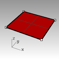
Turn on the control points of the simple rectangular plane on the left.
The surface has four control points, one at each corner—this is a simple untrimmed planar surface that shows the rectangular topology.
-
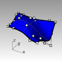
Now, turn on the control points of the curvier surface.
There are many more points, but it is clear that they are arranged in a rectangular fashion.
-
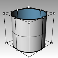
Select the cylinder.
It appears as a continuous circular surface, but it also has a rectangular boundary.
-
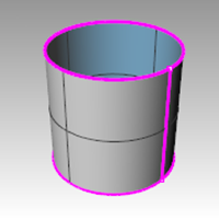
Use the ShowEdges command (Analyze menu: Edge Tools > click Show Edges) to highlight the surface edges.
Notice that a seam is highlighted on the cylinder. The seam that is highlighted represents two edges of the rectangle, while the other two edges are circular at the top and the bottom. The rectangular topology is present here, also.
-
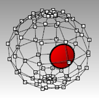
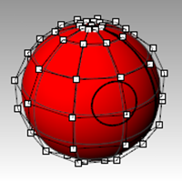
Select the sphere.
It appears as a closed continuous object. -
Use the ShowEdges command to highlight the edges.
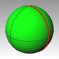
Notice that a seam is highlighted on the sphere. The highlighted seam represents two edges of a rectangular NURBS surface, while the other two edges are collapsed to a single point at the poles. When all of the points of an untrimmed edge are collapsed into a single point, it is called a singularity.
The rectangular topology is present here, also, though very distorted.
-
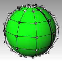
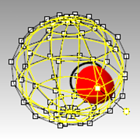
Turn on the Control Points for the sphere.
-
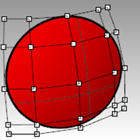
Zoom Target (View menu: Zoom > Zoom Target) draw a select window very tight around one of the poles of the sphere.
-
Select the point at one pole of the sphere and start the Smooth (Transform menu: Smooth) command.
-
In the Smooth dialog box, clear the **Smooth Z **check box, and click OK.
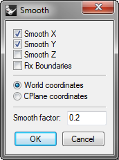
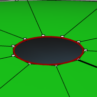
A hole appears at the pole of the sphere. There’s no longer a singularity at this pole of the sphere. ShowEdges will highlight this as an edge as well.
-
Use the Home key to zoom back out.
This is the fastest way to step back through view changes.
Select points
-
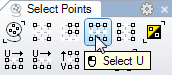
Open the Select Points toolbar.
-
Select a single point at random on the sphere.
-
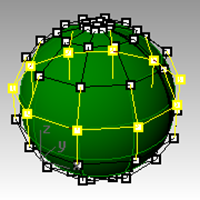
On the Select Points toolbar, click Select U.
An entire row of points is selected.
-
Clear the selection by clicking in an empty area and select another point on the sphere.
-
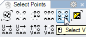
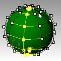
On the Select Points toolbar, click Select V.
A row of points in the other direction of the rectangle is selected. This arrangement into u- and v-directions is always the case in NURBS surfaces. -
Try the other buttons in this toolbar on your own.
Tip: To see at a glance which way the current surface normals are pointing, set any shaded display mode to show colored backfaces. This is one of the settings available in the Display panel (Panels menu >Display) for shaded modes.
Select a bright, distinguishing color like orange, yellow, or cyan.
Exercise 3-2 Observe trimmed surfaces
-
Open the model Trimmed NURBS.3dm.
This surface has been trimmed out of a much larger surface. The underlying four sided surface data is still available after a surface has been trimmed, but it is limited by the trim curves (edges) on the surface.
-
Select the surface and turn on the control points, then drag a few control points.
Control points can be manipulated on the trimmed part of the surface or the rest of the surface, but notice that the trimming edges move around as the underlying surface changes. The trim curve always stays on the surface.
-
Use the Undo command to undo the point manipulation.
Remove the trims from a surface
- Start the Untrim (Surface menu: Surface Edit Tools > Untrim) command.
- Select the single edge of the trimmed surface.
The original underlying surface appears and the trim boundary disappears.
- Use the Undo command to return to the previous trimmed surface.

Detach a trimming curve from a surface
- Start the Untrim command with the KeepTrimObjects option set to Yes (Surface menu: Surface Edit Tools > Detach Trim).
- Select the edge of the surface.
The original underlying surface appears. The boundary edges are converted to curves that are no longer associated with the surface.
- Undo to return to the previous trimmed surface.
Shrink a trimmed surface
- Start the ShrinkTrimmedSrf command (Surface menu: Surface Edit Tools > Shrink Trimmed Surface).
- Select the surface, and press Enter to end the command.
The underlying untrimmed surface is replaced by a one with a smaller range that matches the old surface exactly in that range. You will see no visible change in the trimmed surface. Only the underlying untrimmed surface is altered.
Custom display modes
Assigning a custom color to the backface of a surface in the display mode will help you know the direction of the normal by the display color.
Customizing a display mode will make this preview available from any viewport in any model on your computer that uses your custom display mode.
You will start by customizing the Shaded display mode.
Exercise 3-3 Color the backface
-
If it is not already open, open the model Trimmed NURBS.3dm.
-
Right-click on the **Perspective **viewport title, and pick Shaded.
-
Select the surface and from the **Analyze **menu, click Direction.
-
The surface will be decorated with a 3 sides arrow, similar to construction plane:

The white arrow shows the normal direction. You can think of the normal as the direction that points “outside” or “up.” Enter to exit the command and to return the surface to the normal view. -
The outside and the inside of the surface are not easy to distinguish in the standard **Shaded **display mode.
|  |
|  |
| Outside of surface | Inside of surface |
|
| Outside of surface | Inside of surface |
-
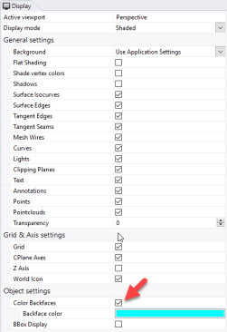
On the **Panel **menu, click to open the **Display **panel.
-
On the **Display **panel, next to Color Backfaces click the check box.

-
Next to Backface color, pick the color swatch.

-
In the **Select Color **dialog, pick Cyan color and pick OK.
-
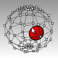
Rotate the view and verify that the backface of the surface is now displayed in cyan.
| |  |
| Outside of surface - same. | Inside of surface - now displays cyan. |
|
| Outside of surface - same. | Inside of surface - now displays cyan. |
