History allows editing or updating objects by editing the input geometry that was used to create the objects. History is useful when there is a need to edit the input of a command or when transformed copies of an object need to stay matched to the original. Only certain commands support history.
History is not the same as a “feature” or “parametric.” History information is saved in the Rhino *.3dm file.
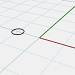
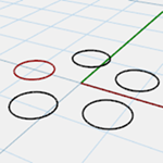
A simple example
- Draw a circle.
- Turn on Record History and Array the circle.
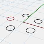
- Scale the original.
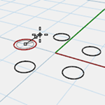
- Watch the arrayed circles update.
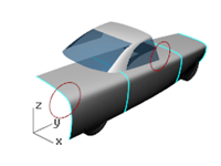
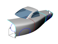
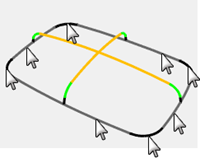
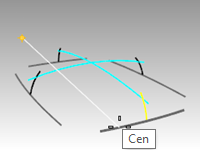
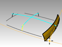
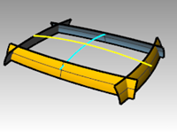
Make a lofted surface
- Open the model History_Intro.3dm.
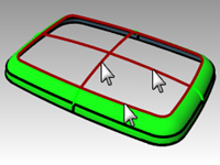
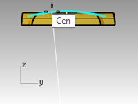
- Select the four cyan colored curves.
- Start the Loft command (Surface menu: Loft), select Normal style, and click OK.
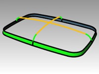
Loft the curves to generate a smooth surface.


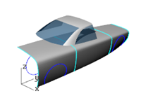
- Turn on the control points and edit the surface.
Turning on surface control points allows the surface to be edited directly as always. However editing the input curves does nothing to change the surface. - **Undo **or delete the loft.
Activating history
History recording is off by default. It must be turned on before running a command to record history for that command. The status of history recording is indicated on the Record History pane on the status bar. If the text in this pane is bold, recording is active. Click the pane to change the status.
To record history for a particular command, click the Record History pane, and then start a command that pays attention to history.
Why is history off by default?
- Unpredictable results. For example, if you Copy with history and make a change, all of the children start to update.
- File size is larger with history enabled.
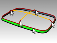
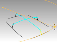
Make a lofted surface with history
- Click in the Record History pane in the status bar to make it bold and active.
- Select the four cyan colored curves.
- Start the **Loft **command (Surface menu: Loft), select Normal style, click OK.
Notice the Record History pane is no longer bold once a command has run.


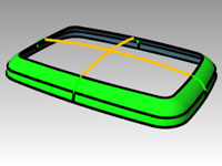
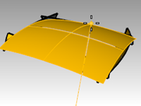
- Select one of the input curves and move it.
The loft surface updates to reflect this new position. - Turn on control points of the input curves.
- Edit the points and the surface will update.


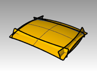
- Select the curves and Rebuild (Edit menu: Rebuild) them to 10 points.
The lofted surface updates to reflect this change as well. Changing degree of the parent curves will also change the degree of the child surface in that direction. - Undo the three previous steps.

Steps in the history chain
- The command must support History.
- History recording must be active when the command is actually run. By default, History recording is turned off and must be activated each time a command is run for which the user wants to record history.
- History updating must be on. This is on by default. When it is on, edits to input objects are immediately reflected in the updated output.
- History can be nested; for example, a curve can be projected onto a lofted surface, and the curve will follow the changes to the lofted surface.
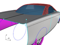
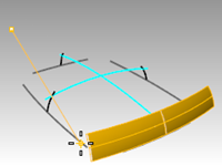
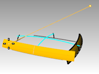
Project a curve onto a surface with history
This part of the exercise will demonstrate an example of nested history. We will be projecting the wheel cutout curves onto the lofted surface.
- First, we will change the construction plane for the **Perspective **viewport.
- On the CPlanes toolbar tab, click Set CPlane World Right.
- Click in the Record History pane in the status bar to make it active.
- Use the Project command (Curve menu: Curve from Object > Project) to project the two wheel cutout curves onto the lofted surface.
- Set the CPlane back to World Top (CPlanes toolbar tab, Set CPlane World Top).
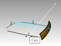
- Select one of the input curves for the loft. Modify it by:
Moving or scaling
Control point editing
Hint: Gumball can be helpful here.
The projected wheel cutout curves update to follow the surface.
Note: Any editing of the outputs will ‘break’ History and the connection between inputs and outputs will be lost. Rhino will put up a warning box when this happens and the user can either Undo to restore the connection, or continue editing and accept the break in History.
History-enabled commands
A list of the history-enabled commands is maintained in the History command help topic.
History-enabled commands
History
HistoryPurge
SelObjectsWithHistory
SelChildren
SelParents
History toolbar
History Options
Inputs to a History-enabled command are called Parents in Rhino and the outputs are called Children.
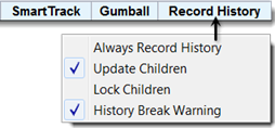
Right-click the Record History pane to change the following options:
Always Record History
This option changes the default behavior so any eligible command will always record history. Use this option with caution. In addition to unnecessarily increasing the file size, it can lead to unexpected behavior. To clear history on particular objects or on all objects, use the HistoryPurge command.
Update Children
Causes child objects to update each time the parent object changes. This increases the time it takes to update complex objects. For very complex edits on the parent objects, turn off updating, make the changes, and then turn Update Children on so that the update happens only once.
Lock Children
This option sets child objects to a locked state. Since directly editing the child objects breaks the connection to the parent objects, locking the child objects prevents accidental editing. In addition, selecting child objects can be cumbersome if they are in the same location as the parent objects. Locked child objects still update when the parent objects are edited.
History Break Warning
This option displays a warning if an operation breaks the connection of a child object to its parent objects. The Undo command will restore history.
Use the History command to control history recording, updating, locking, and warnings.
Change history options
- Click on a curve to get the multi-select box.
If you edit the surface in any way, History for the object will break and Rhino will warn you about this. - Select the surface and drag it. Rhino will warn you that dragging broke history.
- Click OK.

Make sure to Undo after getting a “broken History” warning to restore the connection between inputs and output.

- Right-click in the Record History pane and check the Lock Children option.
This will make it impossible to edit a child in any way that will break history, but you can select it to change its object properties or layer, etc.
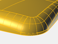
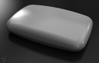
Advanced Surfacing Strategies
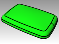
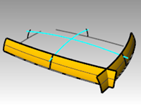
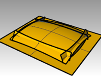
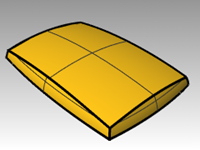
There are several ways to approach making a soft box shape like the illustration below.
In this exercise, we explore two different methods to make the surfaces using the same underlying curves. Our design curves in this example are all tangent arcs.
The first method will use the curves directly. For second method, we will plan ahead and try to take into account the simple underlying shapes suggested by the design curves.
The two approaches are different, but one is not inherently better or contradictory to the other.
Exercise 6-1 Soft corners (part 1)
Make a rectangular shape with a curved top and soft corners
- Open the model Soft Corners.3dm.
- Use the Join command (Edit menu: Join) to join the arcs that form the base rectangular shape.
- Change to the 03 Sweeps layer.
- Use the Sweep1 command (Surface menu: Sweep 1 Rail) to make the first surface.
- In the Sweep 1 Rail Options dialog box, check the Closed sweep option, then click OK.
- Repeat the Sweep1 command to make the second surface.
- Pick the top edge of the surface you just created, then select the cross-sections in order, and press Enter.
- In the Sweep 1 Rail Options dialog box, change the Style to Align with surface, and click OK.
This will insure tangent continuity with the first surface.
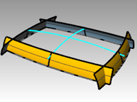
- Use the Patch command (Surface menu: Patch) to fill in the opening at the center.
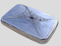
Check the surface with an environment map
- Select the surfaces you made.
- Start the EMap command (Analyze menu: Surface > Environment map).
- Click Adjust mesh and refine the mesh in a similar way that you did for the Zebra surface analysis command.
- Choose the Arches.png or Space Needle.png from the drop-down list in the EMap Options dialog box.
- Tumble the view around.
Note the top surface has a pronounced X-shape in the pseudo-reflections. The surface is not a clean interpretation of the original input curves- there is this extra distortion across the top surface. So, even though we have hit all the input curves, our surfaces are not necessarily very nice.
Soft corners - another method
This time, we will look at the input curves and make some judgments about the best way to construct the surfaces.
One thing to keep in mind is that it is important to make primary surfaces with good curvature
characteristics before building the secondary, or transitional surfaces.
Primary surfaces will be the ones that define the overall shape. They tend to have relatively even curvature, and less curvature than the transitions. Transition surfaces, as the term implies, provide transitions between the primary shape surfaces. These surfaces tend to have higher curvature than the primary surfaces. Fillets and blends, for example, are generally added as transition surfaces.
In this example, we have the four side surfaces and the top surface as primary surfaces. We will add the corners afterward as fillets. Since in our example the input curves are entirely made up of tangent arcs, we can define the side and top surfaces as revolved surfaces. This type of surface is very exact and simple.
Exercise 6-2 Soft corners (Part 2)
-
Change to the 02 Separate Curves layer and turn all the other layers off.
-
Hide the fillet curve at each corner, and the green cross-section curves.
-
Lock the red curves.
-
Use the Extend command (Curve menu: Extend Curve) with an ExtensionLength=10 to extend both ends of the cyan curves and the top of each black arc, press Enter to complete the command.
Each arc is extended at each end using the existing arc radius.
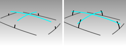
The goal is to extend the arcs enough that they will intersect one another as in the illustration. The exact amount is not critical. -
Change to the 04 Surfaces layer.
-
Use the Revolve command (Surface menu: Revolve) to make surfaces from two adjacent extended vertical curves.
-
Snap to the center of the base curve to place the Start of revolve axis.
-
Press Enter to use CPlane z-axis direction for the End of revolve axis.
If you are in a Perspective viewport, this option will automatically set the axis vertical and save the trouble of locating the second point.
-
Pick the Start angle as shown in the image that is somewhere outside the span of the desired final surface.
Make sure **Ortho **is off at this stage.
The goal is to make a surface that is larger than will eventually be needed to make the box, so the exact starting and ending points are not critical.
-
Pick another point for Revolution angle to create the vertical surface.
-
Create an adjacent vertical surface in the same way.
-
Use the MX and MY aliases you made on the first day to Mirror each of the surfaces around the origin.
Make the top surface
In this example, we will make the top surface by revolving one of the top curves around the center of the other top curve. Since we will be working in the **Perspective **view, it will be necessary to change the construction plane for that viewport.
- Use the Revolve command (Surface menu: Revolve) to make the top surface from the longer top arc.
- Snap to the center of the shorter top arc in the **Right **viewport to place the Start of revolve axis.
- Press Enter to use CPlane z-axis direction for the End of revolve axis.
- Pick the Start angle as shown.
- Pick another point for Revolution angle to create the top surface.

- Use the **CutPlane **command (Surface menu: Plane > Cutting Plane) to make a cutting plane at the origin in the z-axis.
Make the surfaces into a solid
- Use the CreateSolid command (Solid menu: Create Solid) to join and trim the surfaces into a closed solid.
- Use the **FilletEdge **command (Solid menu: Fillet Edge > Fillet Edge) to fillet the edges.
- Set the CurrentRadius to 15, select the four vertical edges, and press Enter to make the fillets.
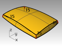
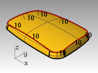
- Repeat the FilletEdge command to fillet the top edges.
- Set the CurrentRadius to 10, select the eight top edges, and press Enter to make the fillets.
The resulting surface is very clean and smooth with no hard edges.
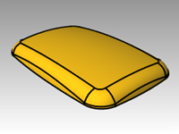
Note: You may notice a defect in a shaded viewport at one or more of the corners. This is a render mesh related defect. There is nothing wrong with the geometry.

Fix the mesh
- Use the Options command to change the mesh settings.
- On the Mesh page, change to a Custom mesh.
Use the settings below.
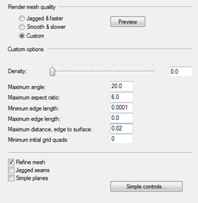
The visual defect goes away.