Deformation tools allow you to deform meshes, lines, surfaces, polysurfaces, and solids without worrying about the integrity of the object.
Start the deformation commands from the Transform menu, or from the Deformation Tools toolbar:

Deforming objects
With CageEdit the deformation of captive objects will take place throughout 3-D space. This setting is important if some of the captive objects are outside of the cage.
CageEdit
Exercise 13-1 Using cage editing to deform an object
Deform an object with CageEdit
-
Open the model CageEdit_Mug.3dm.
-
Open the **Cage **toolbar.

-
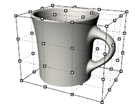
Start the **CageEdit **command (Transform menu: Cage Editing > Cage Edit or Cage toolbar) and select the mug as the captive object.
-
For the control object, choose BoundingBox, and then World.
-
Specify four cage points and degree 3 in each direction.
The degree can be set up to degree 9. The point count must be greater than the degree value in each direction. -
For the Region to edit, choose Global.
-
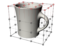
Move the control points on the top of the cage vertically to deform the mug.
Cage points can be moved, dragged, scaled, sheared, rotated, bent, etc.
Limit the region to edit
To deform the handle only, a cage object is needed around the just the handle.
-
Use **ReleaseFromCage **command (located in the Cage toolbar) to select the cage object on the mug.
-
Enter to Delete the cage.
-
Start the Cage command and create a freestanding cage object.
-
Move the cage into place and Scale it before attaching it to the mug
-
Start the CageEdit command.
-
For the Select captive object, select the mug.
-
For the Select control object, select the pre-positioned cage object.
-
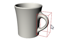
For the Region to edit, choose Local and set a Falloff distance to 5.
This tells Rhino that the distortion of the cage will affect only the region inside the cage, plus a smooth falloff effective over 5 units moving out from the cage itself.
-
Move the two right-most vertical rows of cage points slightly to the right in the Front viewport to increase the size of the handle.
Exercise 13-2 CageEdit the salad fork
While it is possible to use any curve or surface as a control object in CageEdit, there are many cases where the most intuitive solution is to use a curve or surface that is already part of the object.
CageEdit with a surface from the object
In theCageEdit command you will select a surface from the captive object to use as control object.
-
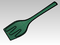
Open the model Salad_Cage.3dm.
-
**Right-click **the end of the **Standard **toolbar.
On the menu, click **Show Toolbar **and check Cage.
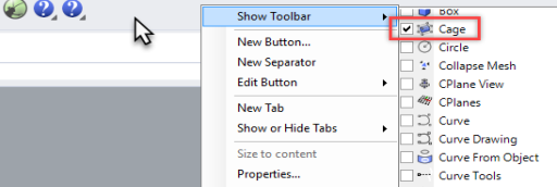
The Cage toolbar will appear.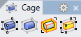
-
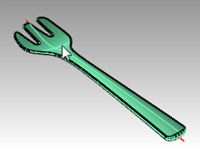
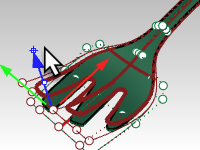
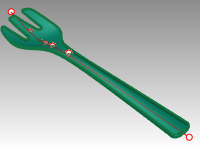
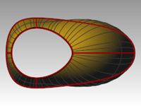
Select the salad fork and start CageEdit command.
-
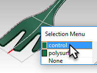
For the Control object, click on the top surface of the fork.
-
At the **Region to edit **prompt, pick Global.
A copy of the surface is extracted from the object and turned into a control object. -
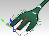
When the control points are on, use the Gumball to move the five points nearest the end vertically.
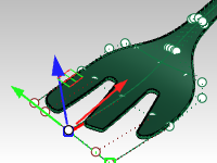
This gives the fork a little more bend to the front of the fork. This typically results in considerable delay and a useless distorted version of the fork.
The reason for this is that the extracted surface does not extend to the full width and length of the fork- the rounded, blended edges fall outside of the control object and therefore it becomes highly distorted as a result. -
Undo.
-
Start the **ReleaseFromCage **command to detach the fork from the control object.
-
Select the control object. From the **Edit **menu, pick Explode.
The **Explode **command will change a control object into normal geometry.
-
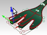
From the **Surface **menu, click Extend Surface (Extendsrf).
-
Pick on the long edges of the surface (Type=Smooth) at a factor of 5.
The surface now extends past all of the fork object.
-
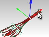
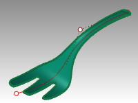
Start **CageEdit **again and select this extended surface as the control object. CageEditing should now result in a clean object.
-
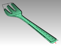
For example, select the two control points that are in the middle of the fork part of the object. Using Gumball, move these down the length of the fork, to increase the amount of dish in the fork.
-
Move the group of points that is at the narrowest part of the handle up or down.
This will increase or decrease the curve in the handle.
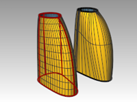
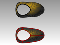
CageEdit with a curve from the object
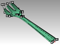
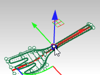
A curve can be used as a control object as well. In many cases it may make sense to use a curve which already has the same basic shape as the object. You can draw such a curve or it may be useful to extract an isocurve from the object itself and use this as the control.
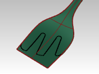
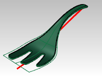
- Re-open the model Salad_Cage.3dm without saving.
The red curve is an extracted isocurve from the bottom surface that has been extended slightly at each end with the **Extend **command.
The reasons for extending the control curve out beyond the geometry are the same reasons as were described above for the surface control object.
Primarily, this is done to limit the distortion in the resulting polysurface. - Select the salad fork and start CageEdit.
- Select the red curve as the Control object.
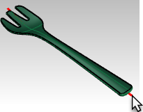
- Edit the shape of the fork by point editing the control object.
Using other deformation tools
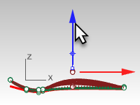
Stretch
The **Stretch **command allows you to scale a selected area of an object in one direction.
Exercise 13-3 Stretch an object
- Open the model StretchWrench.3dm.
- Select the wrench.
- Start the Stretch command (Transform menu: Stretch).
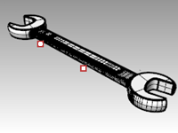
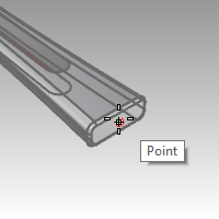
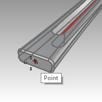
- For the Start and End of axis, snap to the two locked points.
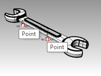
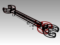
- For the Point to stretch to, pull the cursor to one side or another to stretch or compress the wrench.
The section of the wrench that falls between the points that set the stretch axis is the part that is deformed. The object outside of this initial axis is moved, but not deformed. The shape of working parts of the wrench at either end are not affected, but the overall object is made longer or shorter.
Orient an object on a surface
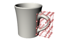
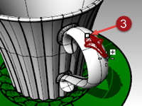
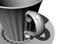
Here the goal is to place the small detail that is off to the side of the cup onto the cup handle. The detail is easy enough to build in a flat, orthographic orientation but would be quite tedious to build accurately in place on a curved surface.
The OrientOnSrf command can place an object on an arbitrarily curved and oriented surface with good control over the placement and can optionally also deform the object to match the curvature of the target surface.
Exercise 13-4 Place a small detail on an object
- Open the model OrientOnSrf_detail.3dm.
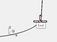
- Start OrientOnSrf, and select the detail object.
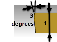
- For the Base point, snap to the point marked 1.
This will be the point that is placed on the target surface. - For the Reference point, snap to the point marked 2.
This point and the line between it and the base point will be used to set scaling and orientation on the target surface. The current CPlane Z direction will be mapped to the target surface normal.
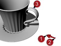
- The Surface to orient on is the handle surface of the cup.
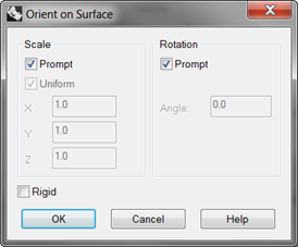
- In the dialog box, make sure the Rigid option is not checked.
This will allow the object to deform against the target surface. - Set Scale and Rotation to Prompt so that you can set these interactively as needed.
Rotation defaults to setting the line between the base and reference points set above to the U direction of the target surface. - Click OK.
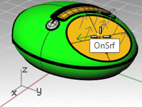
- For the Point on surface to orient to, snap to the point on the handle marked 3.
Notice that in the preview the location corresponding to the base point is what tracks on the target surface.
With the command-line Copy=Yes option, you can place the object without disturbing the flat original and you can place multiple copies. - Set Copy=Yes.
There are other command-line options for Flip, in case the object maps to the wrong side of the surface, and IgnoreTrims.
If IgnoreTrims is set to Yes, the object can be placed anywhere on the underlying surface of a trimmed face, otherwise location is restricted to the trimmed face.
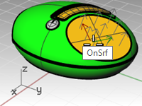
- Click to set the location point.
Since Scale was set to Prompt, you can drag interactively to scale the object or you can type in a scale factor at the command-line.
In this case, a Scale factor of .7 works well. - You can rotate the object on its base point.
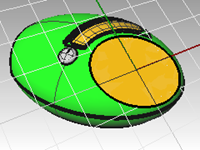
Holding Ortho can lock the angle to match the construction plane, or you can type in an angle at the command-line. In this case, the Rotation angle is zero.
After setting the angle, the object is mapped to the target surface. - At this stage, you can continue to add details to the handle, or press Enter to end the command.
Deform an object in a spiral
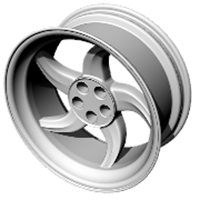
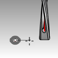
In this example, we will deform the spokes of a wheel to give them a twisted look with the Maelstrom command.
Exercise 13-5 Deform using Maelstrom
- Open the model Maelstrom.3dm.
- Select the spokes of the wheel as the objects to deform and start the Maelstrom command (Deformation Tools toolbar).
- In the Front viewport, set the Center of Maelstrom at 0,0,0.
- For the Radius, snap to the point on the locked circle near the center of the wheel (1).
- For the Second radius snap to the point to the right of the wheel on the arc (2).
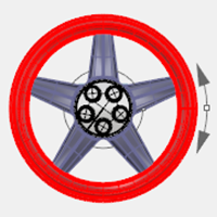
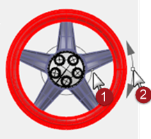
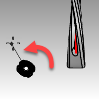
- For the Coil angle, drag the cursor around the circle about 15 degrees to deform the spokes into a soft spiral shape.

Options:
- Copy = Yes/No
- Rigid = Yes/No If Yes, objects will be rotated and moved along the spiral but will not be deformed themselves. This is useful for ‘Maelstroming’ groups and patterns of discreet objects.
Flow along a curve
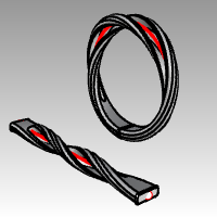
In this example, we will flow an object along a curve while recording history. This will allow us to do a secondary deformation of the original object and see the update on the flowed piece.
Exercise 13-6 Deform an object by flowing it along a curve
-
Open the model Flow & Twist.3dm.
-
On the Status bar, turn Record History on.
-
Right-click the Record History pane, and check the Update Children option. (This should already be checked by default)
-
Select the polysurface and from the **Transform **menu, click Flow along Curve.
Set Copy=Yes, Rigid=No, Local=No, and Stretch=Yes. -
For the Base curve, select the straight line (through the center of the polysurface).
-
For the Target curve, select the circle.
A copy of the polysurface flows around the circle.
-
Twist the original polysurface 360 degrees or more.
Select the original polysurface, and from the **Transform **menu, click the Twist command. -
In the **Perspective **viewport, pick the points at the end of the part as the twist axis.
-
Move the cursor in a counter clock-wise movement to show the final angle 360 degrees or more and pick to preform the Twist.
The polysurface created with the Flow command and History updates to match the twisted polysurface.
Flow
The Flow command re-aligns an object or group of objects from a base curve to a target curve.
Steps
- Select objects.
- Select the base curve near one end.
- Select the target curve near the matching end.
Similar to Flow Along Surface, the **Flow **command lets you flow solids along a curve. This makes designing in 3‑D easier and lets Rhino do all the morphing work.
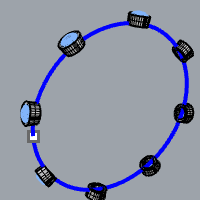
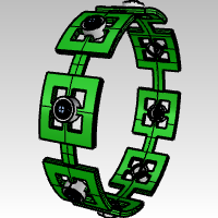
Making a Ring with Flow
Exercise 13-7 Flow the parts of a ring along the shank curve
- Open the model Flow_ring.3dm.
- Select the green polysurface as the object to flow.
- On the Transform menu, click Flow along Curve.
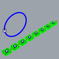
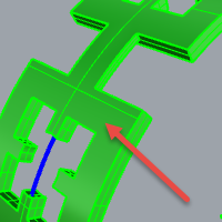
- For the Base curve, select the red linear curve towards the left end.
Note: In the **Perspective **viewport, change the display mode to Ghosted to view and select the base curve more easily.
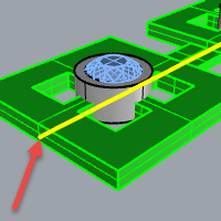
Base curve. - Stop at this stage and confirm the following option settings in the command-line (Copy=Yes Rigid=No Stretch=No).
- As the Target curve, select the circle curve slightly below the point location.
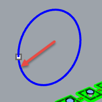
The polysurface is morphed or flowed to the shape of the target curve.
Notice that the polysurface doesn’t flow completely around the circle. - Undo.
You will flow this polysurface a few more times and use different options.
First, you will change the direction of the Flow.
Flow the parts of a ring along the shank curve in a different direction
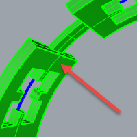
- Repeat Flow along curve with identical steps, except select the Base Curve at the opposite end.
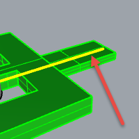
Base curve. - As the Target curve, select the circle curve slightly below the point location.
Notice that the inside and outside of the original polysurface has flipped. - Undo again.
Bottom of original polysurface is on the outside.
Top of original polysurface is on the inside.
Second, you will stretch the original polysurface so that it fits completely around the circle.
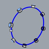
Flow the parts of a ring along the shank curve, stretching it to fit the whole curve
-
Repeat Flow along curve the same way you did it the first time, selecting the Base Curve near the left end.
Note: In the **Perspective **viewport, change the display mode to Ghosted to view and select the base curve more easily.
-
Stop at this stage and confirm the following option settings in the command-line (Copy=Yes Rigid=No Stretch=Yes).
-
Select the circle curve slightly below the point location as the Target curve.
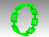
The polysurface is morphed or flowed completely around the circular shape of the target curve. -
Use the What command to confirm that it is a closed solid polysurface.
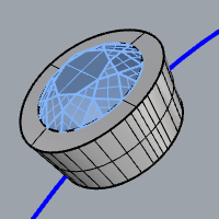
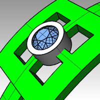
Flow the gems and bezels
- Hide both the original polysurface and the flowed polysurface.
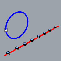
- On the Transform menu, click Flow along Curve.
- For the Objects to flow, you will select the gems and bezels by layer.
- In the Layers panel, Right click on the **Bezel **layer. Pick **Select objects **from the cursor menu.
- In the Layers panel, right click on the Gem_rubylayer. Pick **Select objects **from the cursor menu.
- Enter to close the object selection.
- Next, select the Base Curve near the left end.
- Stop at this stage and confirm the following option settings in the command-line:
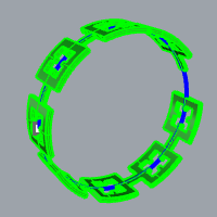
(Copy=Yes Rigid=No Stretch=Yes). - As the Target curve, select the circle curve slightly below the point location.
The bezels and gems are morphed to fit around the circle.
- Examine the results.
The sides of the bezels are not perpendicular, the top surface is not flat, and gem is stretched. - Undo.
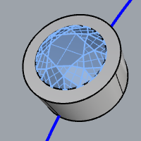
To flow the gems and bezels with Rigid=Yes
- On the Transform menu, click Flow along Curve.
- For the Objects to flow, select the gems and bezels in the Layers panel.
In the Layers panel, right-click on the **Bezel **layer. Pick **Select objects **from the cursor menu.
In the Layers panel, right-click on the **Gem_ruby **layer. Pick **Select objects **from the cursor menu. - Enter to close the object selection.
- Select the Base Curve towards the left end.
- Stop at this stage and confirm the following option settings in the command-line:
(Copy=Yes Rigid=Yes Stretch=Yes). - As the Target curve, select the circle curve slightly below the point location.
The bezels and gems are stretched to fit around the circle, but the objects are not deformed.
- Examine the results.
The sides of the bezels are perpendicular, the top surface is flat, and gem is not stretched.
- Show the green polysurface again.
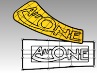
Often you are asked to take an existing design from a 2‑D graphics package and include it as part of a Rhino model.
In the following two exercises, we will move and position the graphic onto the model.
In this exercise, we will make a custom construction plane, import an Illustrator file, and place a logo on some surfaces.
Exercise 10-1 Importing an Adobe Illustrator file
Open and setup the model
- Open the model Air Cleaner.3dm.
- In Rhino Options, Modeling Aids, set the Construction planes to use Standard construction planes.
The following techniques will not work if the construction planes are set to use Universal construction planes.
Import a file
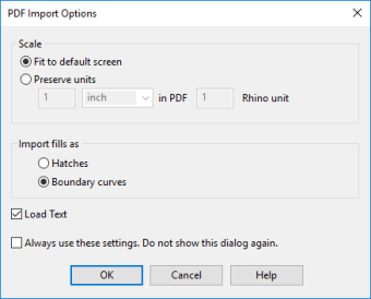
- Start the Import command (File menu: Import).
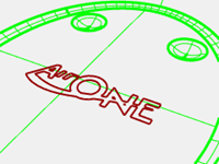
- Change the Files of type to Adobe Illustrator (*.ai), and choose the AirOne_Logo.ai to import.
- In the AI Import Options dialog box, selection “Fit to default screen”, click OK.
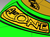
The logo curves appear at the origin of the Top construction plane, are selected, and on the Default layer.
- While the imported geometry is still selected, use the Group command to group the various curves together.
This makes it much easier to select all of the curves and not leave any behind in the following transform steps. - Start the Layer command.
- Turn off the Logo layer in the Layer panel.
- Right-click on the Logo layer, then click Copy Objects to Layer to make a copy of the logo on the Logo layer.
We will use this copy later for another part of the exercise. - Turn off all the layers except Default, Body and Top Surface.
Create a custom construction plane
We need to set a construction plane to the flat surface. The **CPlane **command will allow us to do this but the X and Y directions of the new custom construction plane will be mapped to the u- and v-directions of the target surface respectively. The **Dir **command will tell you how the u- and v-direction are pointing on the surface, and allow you to change the directions of each.
- Set the Display mode of the **Perspective **viewport to wireframe.
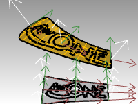
- Select the flat disc shaped surface, then from the Analyze menu, select Direction.
This displays the current surface normal direction and the U/V directions. It is important to know the u- and v-directions of the surface.
The white arrows show the surface normals. A cursor with a red and green arrow appears when you move over the selected surface.
The red arrow indicates the U direction and the green arrow indicates the V direction. - At the command-line, notice the options for changing the directions of the surface. You can click on these to change the surface directions. The cursor and surface normals will update accordingly.
When all changes are made, press Enter to accept.
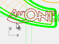
The goal is to have the U and V as in this image.
In this way, the new construction plane will map to the surface accordingly and the geometry can be mapped to the construction plane predictably. - In the Perspective viewport, use the CPlane command with the Object option (View menu: Set CPlane > To Object) or (Viewport title right-click menu: Set CPlane > To Object) to set the construction plane to the surface.
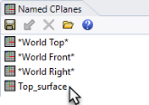
The x- and y-axes are parallel to the u- and v-directions of the surface as you set them in the previous step. - In the **Named Cplanes **panel, save the new construction plane as Top_surface This will make it easy to retrieve in later steps.
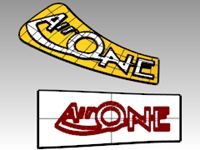
Map the logo curves to the new construction plane
The command we will use to move the logo to the flat disk shaped surface uses the position of the object relative to a construction plane.
-
Make the Top viewport active. The Display mode of the **Top **viewport should be set to Wireframe.
-
Select the curves in the Top viewport.
-
On the Staus Bar, click Record History.
-
Select the logo curves
-
On the **Transform **menu, click **Orient **and Remap to Cplane.
This starts the RemapCPlane command
The **RemapCPlane **command depends upon the active construction planes at each stage, so it is important to pick in the correct viewports.
-
Click in the Perspective viewport with the custom CPlane.
You could use the Copy=Yes option in this command so that a copy is remapped instead of the original.
The logo is positioned in the same relative position on the custom construction plane as it was in the active viewport.
-
Using Gumball, Rotate, Move, or Scale the original logo to a new position. Since **History **was used, changes to the original (or parent) curves update the copy (or child) curves that were remapped to the custom cplane in the **Perspective **viewport.
For an accurate view of the surface and the curves relative to a custom cplane, use the Plan command in the Perspective viewport. This sets the view to a parallel projection looking straight on at the cplane.
Extrude the logo
You will extrude the logo into a polysurface.
- Make the **Perspective **viewport active.
- Select the remapped logo curves.
- From the **Solid **menu, click **Extrude Planar Curve **and Straight.
- In the **ExtrudeCrv **command, click to set the BothSides=yes option .
- Type 1 mm and Enter to set the extrusion height. Enter to accept and extrude.
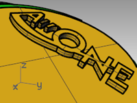
The text is now a closed polysurface. However, there is no draft angle in this extrusion that will assist in removal from a mold. Next you will **Undo **and extrude again with draft angle option. - From the **Edit **menu, click Undo.
Extrude logo with tapered option
In this extrude, we will extrude the logo with the tapered option and then difference it from the top surface.
-
Make the **Perspective **viewport active.
-
From the **Solid **menu, click **Extrude Planar Curve **and Tapered.
-
In the **ExtrudeCrvTapered **command, click to set the DraftAngle to -3 degrees.
-
Enter to complete the command.
Setting the DraftAngle to posivitve3 degrees, will produce incorrect results..


-
Type -1 mm and Enter to complete the extrude.

Note: Using a positive distance and a positive angle will change the extrusion height and angle to the incorrect result.
Difference the logo from the surface
You will engrave the text into the planar surface with the **BooleanDifference **command. The BooleanDifference will remove the solid text from the surface and create the engraving. When the boolean is complete, check to verify that there are no openings or naked edges that were introduced as a result of the boolean.
- Select the top surface.
- From the **Solid **menu, Difference.
Select all the extruded logo and set **DeleteInput **to Yes
- Enter to complete the **Difference **command.
Note: If the Difference fails, move the extruded text slightly above the surface and try the BooleanDifference again.
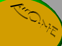
- Pick the top surface.
- From the **Analyze **menu, pick **Edge Tools **and Show Edges.
- Select Show Naked Edges.
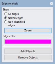
A successful Boolean Difference should result in 1 naked edge around the perimeter of the surface, and no naked edges in the interior.
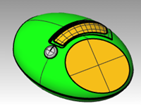
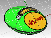
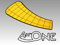
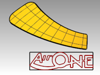
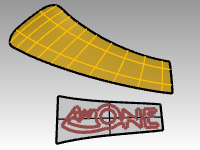
Flow the logo onto a free-form surface with history
In this part of the exercise, you will position the logo geometry by flowing it along the cutout surface. This surface is not flat so you will use a different transform tool, Flow along Surface, to move the logo and bend it along the surface. Flow along Surface morphs objects from a source surface to a target surface. It uses the UV of the surfaces to determine how it flows. It is important that the source and target surfaces have the same relative UV direction for a successful flow.
By enabling history recording before you Flow along Surface, you will be able to change the input and quickly affect the result. The logo is located on the Logo layer. You work only with the logo and the surface in this part of the exercise by turning off all the other layers.
Make the base surface
- Start the Layer command and make the Cutout layer the current layer.
- Turn off all the layers except Cutout and Logo.
- Use the BoundingBox command (Analyze menu: Bounding box) to make a rectangle around the logo.
- Use the PlanarSrf command (Surface menu: Planar Curves) to make a surface from the bounding box.
Flow the logo curves onto the cutout surface
-
On the Status Bar, turn on Record History. It will appear bold.
-
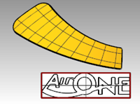
Use the FlowAlongSrf command (Transform menu: Flow along Surface) to move the logo onto the cutout surface. Pick the white surface as the base surface.
Notice that the curve does not fit the surface.
-
Turn on the control points on the base surface and move them to make the surface a little larger in all dimensions.
Since history was on when flowing the curve, any adjustment to the base surface changes the way the curve fits on the cutout surface.
-
Use the ChangeDegree command (Edit menu: Change Degree) to change the base surface to degree 3 in both the U and the V directions.
-
Adjust the control points further to fine tune the way the curve fits on the cutout surface.
-
Undo the booleans and previous FlowAlongSurf.
-
Use the Dir command to check the UV directions of the cutout surface.
-
Use the Dir command to adjust the UV directions of the base surface to match the direction of the cutout surface.
Raise the logo lettering and flow it onto the cutout surface
Next you will flow the solid logo onto the cutout surface.
- Use the ExtrudeCrv command with the BothSides option to make the text 3‑D from the original curves.
The extrusion distance should be 1 mm.
- From the Transform menu, click Flow along surface.
History is not needed this time, since all the needed adjustments were already done on the base surface.
- Use the BooleanUnion command to join the logo with the cutout surface.
- From the **Edit **menu, pick **Undo **.
- Next use the BooleanDifference command to difference or engrave the logo into the cutout surface.

Flow the tapered logo
This time you will flow the curves instead. You will turn off the layer that contains the last FlowAlongSrf.
-
Turn on the Cutout_02 layer and make it the current layer.
-
Turn off the **Cutout **layer.
-
From the **Solid **menu, click Extrude Planar Curve, then Tapered.
-
Set the distance to** 1** mm and the Draft Angle to** 3 **degrees. Enter to extrude.
-
Group all the solid logo letters for easy selection.
-
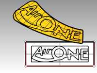
Use the FlowAlongSrf command to translate the solid logo onto the cutout surface.
Use the new base surface and click ConstrainNormal=No.
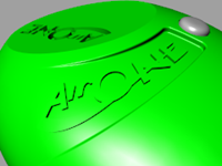
The resulting flowed text should line up exactly with the previously flowed curves.
Notice too that the embossed letters may be tapered outward in some locations. This would make it impossible to pull the surface from a mold, even though you took the trouble to taper the extruded letters originally.
To fix this, Undo, and flow again, but next set ConstrainNormal=Yes. -
From the **Edit **menu, pick **Undo **.
-
Use FlowAlongSrf command again to translate the solid logo onto the cutout surface.
Use the new base surface and pick ConstrainNormal=Yes.
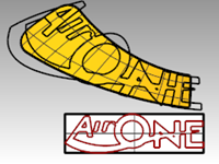
|  |
|
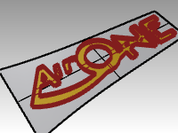
1) ConstrainNormal=No
The resulting flowed text lines up exactly with the previously flowed curves. Embossed letters may tapered outward in some locations
2) ConstrainNormal=Yes.
Here the flow operation maps from the flat version to the target surface without mapping to the target surface normal directions.
The base vertical direction is kept.
|
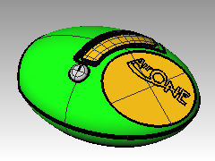
- Use the BooleanUnion command to join the tapered logo with the cutout surface.
Make a model from a 2‑D drawing
One of the more difficult modeling tasks in modeling is to interpret a set of 2-D views into a 3-D model. Very often, the drawings are precise in some areas and inexact in areas where complex surface transitions must take place in three dimensions.
It is best to consult directly with the designer to clarify difficult areas, but this is not always possible. Usually there are discrepancies between the views.
If there is no physical model available as reference, some decisions must be made along the way about the best way to interpret the control drawing. For example, you will have to consider which view to consider the most accurate for a given feature.
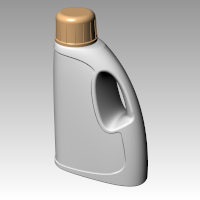
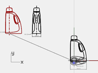
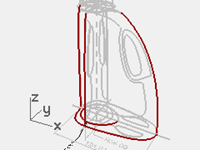
In the following exercise, we will explore some strategies to create a blow-molded plastic bottle from a set of 2‑D drawings. In this exercise, we have a control drawing showing three views of the bottle. It is roughly dimensioned, but we need to hold to the designer’s curves wherever possible.
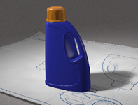
We will only have time to finish the first stage of this model in class. We will complete the bottle surfaces, but the details will be left out. Included in the models folder is a finished bottle for your review.
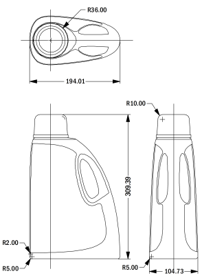
Control drawing
Exercise 10-2 Making the detergent bottle
Group the parts
- Open the model Detergent Bottle.3dm.
- In the Top viewport, window select the objects that make the **Top **view (lower left) including the dimensions of the 2‑D drawing.
- Use the Group command to group the selected objects (Edit menu: Groups > Group).
- Repeat the previous steps to group the objects for the **Front **view (upper left) and the **Right **view (upper right).
Each of the views is a separate group of objects.
Orient the Top view
- Select the **Top **view group.
- Use the ChangeLayer command (Edit menu: Layers > Change Object Layer) to change the layer to the 2D Template Top layer.
- In the Top viewport, use the Move command to move the center of the circles to 0,0.
Orient the Front view
- Select the **Front **view group.
- Use the ChangeLayer command to change the layer to the 2D Template Front layer.
- In the Top viewport, use the Move command to move the intersection of the center line and the horizontal line at the bottom to 0,0.
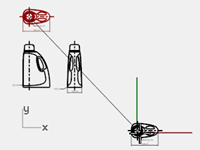
- While the **Front **view group is still selected, start the RemapCPlane command (Transform menu: Orient > Remap to CPlane) in the Top viewport.
- Click in the Front viewport.
The view is oriented in 3‑D space.
Orient the Right view
- In the Top or Perspective viewport, select the **Right **view group.
- Use the ChangeLayer command to change the layer to the 3D Template Right layer.
- In the Top viewport, use the Move command to move the intersection of the center line and the horizontal line at the bottom to 0,0.
- Use RemapCPlane to map the **Right **view curves to the Right construction plane.
The view is oriented in 3‑D space.
Frequently 2‑D curves for design control drawings will not be as carefully constructed as you like for making accurate geometry. Before building 3‑D geometry from the 2‑D curves, check the curves and correct any errors that can be found.
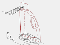
Create the 3‑D curves
The inset part of the bottle will be cut into the surface later. For the moment, we just need to build the outer surfaces. The fillets at the top and bottom indicated in the curves can be left out of the initial surface building and added in as a separate operation. We will need to extend or redraw the edge curves to bypass the fillets and meet at hard corners before making the surfaces.
Several surfacing tools could be used to build the initial surfaces: A Two-Rail Sweep or a Surface from Network of Curves are the obvious choices.
Network surfaces do not pay any attention to the curve structure, only the shape. All curves are refit and the resulting surface has its own point structure.
Other commands including the Sweep tools, lofting and edge surfaces do pay attention to the curve structure in at least one direction. In these cases, it often pays to use matched curves as cross sections. The choice of surfacing tools may well determine the way in which the actual input curves are created.
- Select the groups you made in the previous step, use the Ungroup command (Edit menu: Groups > Ungroup) to ungroup them.
- Select the curves from each 2‑D template view that define the outer surface and Copy them to the 3D Curves layer.
Since the bottle is symmetrical on both sides of the X-axis, you will only need to copy the curves on one side. They will be mirrored later. - Use the OneLayerOn command (Edit menu: Layers > One Layer On) to set the 3D Curves layer.
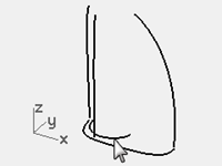
- Move the curve defining the top surface of the bottle to the same height as the top of the vertical curves.
Use SetPt or Move with the Vertical option in the Perspective viewport.
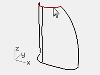
- The vertical curves now can be extended past the fillet curves so that they meet the top and bottom curves exactly on the endpoints of these curves.
One way is to extend the vertical curves using Extend with Type=Smooth.
Snap to the End or Quad points of the top curve and the base curve at the bottom.
Extending the curves in this way will add complexity to the curves. If it is important to keep the curves simple and well matched, it may be better instead to adjust the points on the existing curves to extend them.
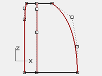
- Undo the Extend operation, and instead point edit the curves directly.
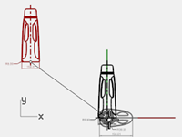
You can make a duplicate set of curves and edit one of each leaving the original in place as a template. - Mirror the base, top and side curve visible from the **Right **view to the other side.
The result should be a set of eight curves that define the surface.
Most of these curves are essentially the original curves from the 2‑D drawings but rearranged in 3‑D.
- Join the base curves and the top curves into a closed loop.
The curves are set up for a surface from a curve network or a two-rail sweep.
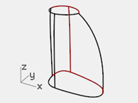
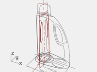
Make a surface for the bottle with a sweep
From the drawing these are the only curves we have available to define the shape, so we will use these curves directly to create the surface.
- Make the Surfaces layer current.
- Window select the curves, and try Sweep2 to make a surface then Shade the viewport.
Notice the shape gets severely out of control at the rounded side of the bottle.
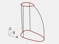
- Move this surface to the side for the moment.
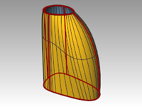
While it is possible to rearrange or add curves to make the Sweep2 work better, it is worth checking how a surface from a Curve Network will work with the same set of curves. - Select all of the curves, again, then use the NetworkSrf command to create the surface.
The NetworkSrf command handles this set of curves much more gracefully.
On your own
- Make the inset surface and the handle.
- Fillet the edges where indicated in the 2‑D drawing.
- Model the threads and cap
A finished bottle, Finished Detergent bottle.3dm, is included in the Model folder for your review.