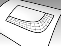
The continuity characteristics for curves can also be applied to surfaces. Instead of dealing with the endpoint, second, and third points, entire rows of points at the edge, and the next two positions away from the edge are involved. The tools for checking continuity between surfaces are different from the simple **GCon **command.
Analyze surface continuity
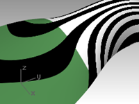
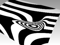
Rhino takes advantage of the OpenGL display capability to create false color displays for checking curvature and continuity within and between surfaces. These tools are located in the Analyze menu, under Surface. The tool, which most directly measures G0-G2 continuity between surfaces, is the Zebra command. Zebra analysis simulates reflection of a striped background on the surface.
Note: An OpenGL graphics accelerator card is not necessary to use these tools, although they may work faster with OpenGL acceleration.
Match surface continuity
The command used to establish G0, G1 or G2 continuity between surfaces is the MatchSrf command.
Match surface options
| Option | Description |
|---|---|
Average surfaces
| Both surfaces are modified to an intermediate shape. | | Refine match | Determines if the match results should be tested for accuracy and refined so that the faces match to a specified tolerance. | | Match edges by closest points | The surface being changed is aligned to the edge it is being matched to by pulling each edge point to the closest point on the other edge. | | Preserve other end | If the surface does not have enough points its degree is raised (up to a maximum of 5), until there are enough points. |
Isocurve direction adjustment
Specifies the way the parameterization of the matched surfaces is determined.
| Option | Description | | Automatic | Evaluates the target edge, then uses Match target isocurve direction if it is an untrimmed edge or Make perpendicular to target edge if it is a trimmed edge. | |
Preserve isocurve direction
| As closely as possible, keeps the existing isocurve directions the same as they were in the surface before matching. | | Match target isocurve direction | Makes the isocurves of the surface that is being adjusted parallel to those of the surface it matches. | | Make perpendicular to target edge | Makes the isocurves of the surface that is being adjusted perpendicular to the edge being matched. |
Surface continuity and MatchSrf
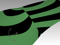
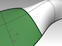
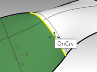
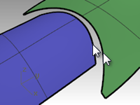
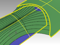
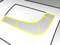
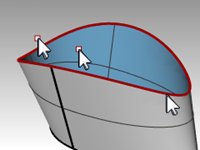
The MatchSrf command takes surface edges as input and modifies one or both of the surfaces. You need to tell the command exactly which edge to change and then which edge to match to the target surface. We will match the white surface’s edge to the green one first. Both the edge to change and the edge to match to are untrimmed on these surfaces.
While MatchSrf is generally used to adjust surfaces that are fairly close to being at the desired continuity, this example is somewhat exaggerated in order to clearly show the functionality and options.
Exercise 5-1 Practice matching surface continuity
-
Open the model Surface Continuity.3dm.
-
Start the MatchSrf command (Surface menu: Surface Edit Tools > Match).
-
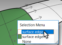
Select the edge of the white surface on the edge nearest the green surface.
-
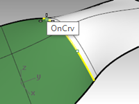
Select the edge of the green surface near the same location as the selection point on the white surface edge and press Enter.
-
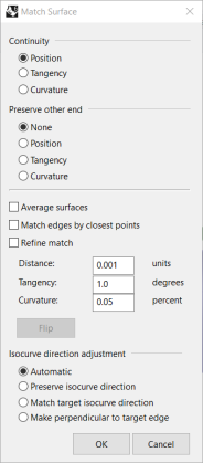
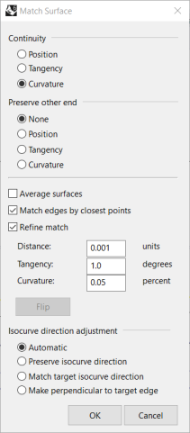
In the Match Surface dialog box, choose Position as the desired Continuity, choose None for Preserve other end, clear the Refine match options, and for Isocurve direction adjustment, choose Automatic.
Make sure all other check boxes are unchecked.
-
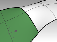
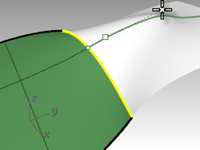
A shaded preview is automatically generated so you can see what the result will be like.
-
Click OK.
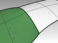
The edge of the white surface is pulled over to match the edge of the green one.
Check the continuity with Zebra analysis
- Check the surfaces with Zebra analysis tool (Analyze menu: Surface > Zebra).
This command relies on an approximation of the surface for its display information.
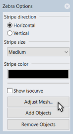
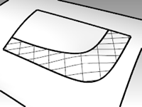
By default, the mesh generated by Zebra may be too coarse to get a good analysis of the surfaces. If the display shows very angular stripes rather than smooth stripes on each surface, click the Adjust mesh button on the Zebra Options dialog box.
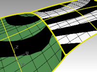
In general, the analysis mesh should be much finer than the normal shade and render mesh meshes.
It is a good habit to set these meshes the first time you use a surface analysis display mode in a model. This setting is then saved in the file. - Use the Detailed Options to set mesh parameters.
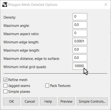
For this type of mesh, it is often easiest to zero out (disable) the Maximum angle setting and rely entirely on the Minimum initial grid quads setting. This number can be quite high but may depend upon the geometry involved.
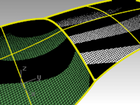
In this example, a setting here of 5000 to 10000 will generate a very fine and accurate mesh.
The analysis can be further improved by joining the surfaces to be tested. - Join the two surfaces.
This will force a refinement of the mesh along the joined edge and help the Zebra stripes act more consistently.
There is no particular correlation between the stripes on one surface and the other except that they touch, indicating G0 continuity. - Undo the Join.
Match the surface to tangency
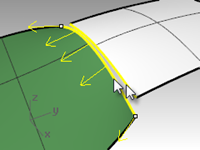
- Use the MatchSrf command (Surface menu: Surface Edit Tools > Match) again with the Tangency option for Continuity.
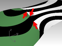
When you pick the edge to match you will get direction arrows that indicate which surface edge is being selected. The surface that the direction arrows are pointing toward is the surface whose edge is selected.
- Check the surfaces with Zebra analysis.
- Rotate the view to view along the seam.
The ends of the stripes on each surface meet the ends on the other cleanly, though at an angle.
This indicates G1 continuity.
Match the surface to curvature
- Use the MatchSrf command (Surface menu: Surface Edit Tools > Match) with the Curvature option.
- Check the surfaces with Zebra analysis.
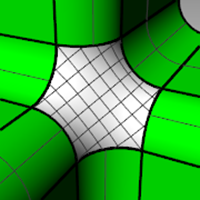
The stripes now align themselves smoothly across the seam. Each stripe connects smoothly to the counterpart on the other surface.
This indicates Curvature (G2) continuity.
Note: Doing these operations one after the other may yield different results than going straight to Curvature without first using Position. This is because each operation changes the surface near the edge, so the next operation has a different starting surface.
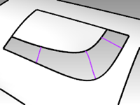
Add knots to control surface matching
As in matching curves, MatchSrf will sometimes distort the surfaces more than is acceptable in order to attain the desired continuity. We will add knots to surfaces to limit the influence of the MatchSrf operation. The new second and third rows of points will be closer to the edge of the surface.
Surfaces can also be adjusted with the **EndBulge **command.
Add a knot to a surface
- Undo the previous operation.
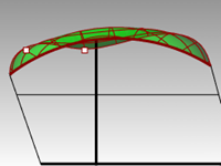
- Use the InsertKnot command (Edit menu: Control Points > Insert Knot) to insert a row of knots near the end of the white surface.
When this command is used on a surface, it has more options.
You can choose to insert a row of knots in the U-direction, the V-direction, or both.
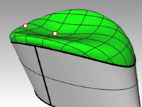
Choose Symmetrical to add knots at opposite ends of a surface. - Use MatchSrf to curvature match the surface to the other.
Notice that the new matched surface is different from the old one.
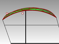
Use EndBulge to edit the surface shape
The EndBulge command lets you edit the shape of a surface without changing the tangent direction and the curvature at the edge of the surface. This is useful when you need to alter the shape of a surface that has been matched to another surface.
EndBulge allows you to move control points at a specified location on the surface. These points are constrained along a path that keeps the direction and curvature from changing.
The surface can be adjusted equally along the entire selected edge or along a section of the edge. In the latter case, the adjustment takes place at the specified point and tapers out to zero at either end of the range. Either the start or endpoint of the range can be coincident with the point to adjust, thus forcing the range to be entirely to one side of the adjustment point.
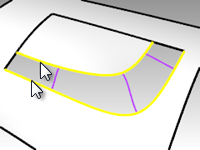
Adjust the surface using end bulge
- Start the EndBulge command (Edit menu: Adjust End Bulge).
- For the surface edge to adjust, pick the edge of the surface on the right.
- For the Point to edit, pick a point on the edge at which the actual adjustment will be controlled.
You can use object snaps and reference geometry to select a point with precision.
- For the Start of region to edit, pick a point along the common edges to define the region to be adjusted.
- For the End of region to edit, pick another point to define the region to be adjusted.
To select a range at this point, slide the cursor along the edge and click at the beginning and endpoints of the range. If the whole edge is to be adjusted equally, press Enter.
- For the Point to adjust, select one of the points that are displayed.
Rhino shows three points, of which you are allowed to manipulate only two. When you move the second point, Rhino also moves the third point that is not being directly manipulated in order to maintain the continuity. If you move the third point it won’t change the second point - Drag the point and click to adjust the surface.
If maintaining the G2 curvature-matching condition at the edge is not needed, use the Continuity=Tangency option to turn off one of the two points available for editing. Only G1 will be preserved. - Press Enter to end the command.
Match surfaces
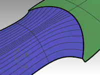
The **MatchSrf **command does not allow matching a trimmed edge to an untrimmed edge. You must work from the untrimmed edge to the trimmed edge.
Match an untrimmed surface to a trimmed surface
- Start the MatchSrf command (Surface menu: Surface Edit Tools > Match).
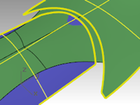
- Select the edge of the green surface on the edge nearest the blue surface.
The edge will not select and you will see the following message on the command-line:
Edge must be on the edge of a surface (not a trimmed edge).
Select an untrimmed surface edge to change (MultipleMatches).

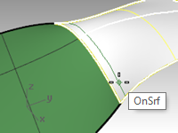
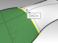
- Instead, select the untrimmed edge of the blue surface on the edge nearest the green surface.
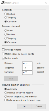
Select the trimmed edge of the green surface near the same location as the selection point on the blue surface edge. - In the Match Surface dialog box, choose Curvature as the desired Continuity, choose None for Preserve other end, check the Match edges by closest points option, and for Isocurve direction adjustment choose Automatic.
Make sure all other check boxes are cleared.
A preview is automatically generated so you can see what the result will be like.
Notice that the blue surface does not include the entire untrimmed edge of the green surface. It only extends as far as the closest point from the original surface.
- In the Match Surface dialog box, clear the Match edges by closest points option, and check the Refine match option.
- Toggle through the Isocurve direction adjustment and the Preserve other end options to see what happens to the matched surface.
- When finished click OK.
Surfacing commands that pay attention to continuity
Rhino has several commands that can build surfaces using the edges of other surfaces as input curves. They can build the surfaces with G1 or G2 continuity to those neighboring surfaces. The commands are:
- NetworkSrf
- Sweep2
- Patch (G1 only)
- Loft (G1 only)
- BlendSrf (G1 to G4)
The following exercises will provide a quick overview of these commands.
Exercise 5-2 Create a surface from a network of curves
- Open the model Continuity Commands.3dm.
On the Surfaces layer, two joined surfaces have been trimmed leaving a gap. This gap needs to be closed up with continuity to the surrounding surfaces. - Turn on the Network layer, if it is not already on, and make it current.
Several curves already in place define the required cross sections of the surface. - Use the NetworkSrf command (Surface menu: Curve Network) to close the hole with an untrimmed surface using the curves and the edges of the surfaces as input curves.
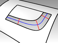
- For the **Select curves in network **option, select the four edges that border the opening and the four curves inside the opening and press Enter.
Note that there is a maximum of four edge curves as input. You can also specify the tolerances or maximum deviation of the surface from the input curves.
By default, the edge tolerances are the same as the model’s Absolute Tolerance setting. The interior curves’ tolerance is set 10 times looser than that by default.
- In the Surface From Curve Network dialog box, choose Curvature continuity for all the edges, and click OK.
The surface that is created has curvature continuity on all four edges. - Check the resulting surface with Zebra analysis.
Make the surface with a two-rail sweep
- Use the OneLayerOn command to open the Surfaces layer by itself again, and then click in the layers panel of the status bar, and select the Sweep2 layer.
- Start the Sweep2 command (Surface menu: Sweep 2 Rails) and select the long surface edges as the rails.
- Select one short edge, the cross-section curves, and the other short edge as profiles.
- Choose Curvature for both Rail curve options.
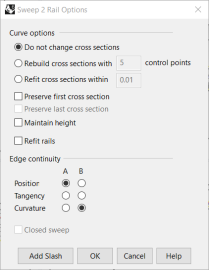
Since the rails are surface edges, the display labels the edges, and the Sweep 2 Rails Options dialog box gives the option of maintaining continuity at these edges.

- Click OK.
- Check the resulting untrimmed surface with Zebra analysis.
Create a patch surface
The Patch command builds a trimmed surface, if the bounding curves form a closed loop. Patch can match continuity to G1 if the bounding curves are edges. The Patch command:
- Can use unlimited curves or points for input
- Ignores noise of many control points
- Is good for scanned data
- Is good for reverse engineering
Make a patch surface
- Turn on the Surfaces and Patch layers.
- Turn all other layers off.
- Start the Patch command (Surface menu: Patch).
- Select the edge curves and the interior curves, and then press Enter.
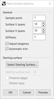
- In the Patch Surface Options dialog box, set the following options:
Set Sample point spacing to 1.0.
Set Stiffness to 1.
Set Surface U and V spans to 10.
Check the Adjust tangency and Automatic trim options, and click OK.
**Sample point **spacing sets the nominal distance along the input curve between sample points. The minimum is eight points per curve.
Surface U and V spans value sets spans for the patch surface. The default value is 10 spans for both the U & V direction.
**Stiffness **value is used to help Rhino build the patch surface by first finding the best fit plane (PlaneThroughPt) through the selected and sampled points along curves. Then the surface deforms to match the points and sampled points. The Stiffness setting tells how much you allow the best fit plane to deform. The bigger the number, the “stiffer” and more rectangular and planar the resulting surface will be.
**Preview **to check the result.
**Adjust tangency **to patch to the tangent direction of surfaces if the input curves are edges of existing surfaces.
 12. Join the surfaces.
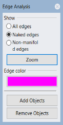
 15. Use the ShowEdges command (Analyze menu: Edge tools > Show Edges) to display naked edges.
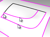
If there are naked edges between the new patch surface and the existing polysurface the settings may need to be refined.
- Check the results visually with Zebra analysis.
Patch options
The Patch command can use point objects as well as curves and surface edges as input. This exercise will use point and edge inputs to demonstrate how the Stiffness setting works.
Exercise 5-3 Make a patch from an edge and points
- Open the model Patch Options.3dm.
- Start the Patch command (Surface menu: Patch) and select the two point objects and the top edge of the surface as input.
- Check the Adjust tangency and Automatic trim options, set the Surface spans to 10 in each direction.
- To get a good view of the two point objects, make the **Front **viewport the active viewport and set it to a wireframe or ghosted view.
- Set the Stiffness to 0.1 and click the Preview button.
With lower setting for stiffness, the surface fits through the points while maintaining tangency at the surface edge. This can show abrupt changes or wrinkles in the surface. - Set the Stiffness to 5 and click the Preview button again.
With higher stiffness settings, the patch surface is made stiffer and it may not pass through the input geometry. On the other hand, the surface is less apt to show abrupt changes or wrinkles, often making a smoother and better surface.
With very high stiffness numbers, the edges also may have a tendency to pull away from the intended input edges.
High stiffness number = the more rectangular and planar the resulting surface will be
Low stiffness number = the smoother (fairer) the resulting surface will be
More spans = greater density of control points
Lofting
The Loft command also has built in options for surface continuity.
Exercise 5-4 Make a lofted surface
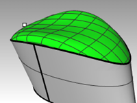
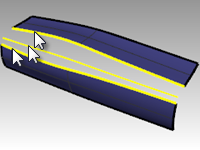
- Open the model Loft.3dm.
- Start the Loft command (Surface menu: Loft).
- Select the lower edge curve, the curve, then the upper edge curved, and press Enter.
When picking the curves, pick near the same end of each curve. This will insure that you do not get a twist in the surface.
- In the Loft Options dialog box, set the Style to Normal, and check the boxes for Match start tangent and Match end tangent options.
- Press Enter when done.
The new surface has G1 continuity to the original surfaces.
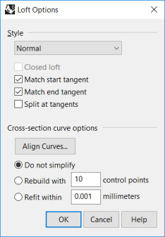
Style:
Loose—similar to control point curve
Straight—similar to polyline
Normal/Tight—similar to interpolated curve - Check the results with Zebra analysis.
Blends
The next command that pays attention to continuity with adjoining surfaces is BlendSrf.
**BlendSrf **will also use the **Record History **setting.
If **Record History **is on in the Status Bar when the **BlendSrf **command is used to create a surface, editing the input curve will update the surface.
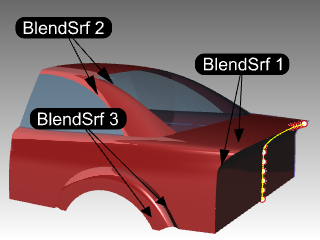
The three blends in this file will serve to illustrate the basic features of the BlendSrf command. The controls inside BlendSrf can be used to vary the character of the blended shape.
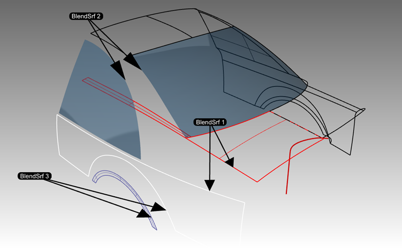
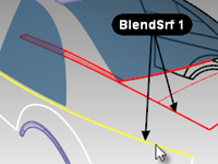
Exercise 5-5 Make a surface blend (BlendSrf 1)
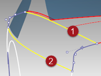
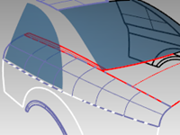
In BlendSrf 1, we will create the transition between the trunk lid and side surfaces of the car body.
-
Open the model Blend.3dm.
-
Start the BlendSrf command (Surface menu: Blend Surface).
-
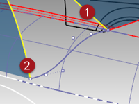
You will blend the full length of the gap between the white side surface and the red surfaces. The ChainEdges option will allow you to select more than one edge segment.
At the **Select first edge **prompt, click the command-line option ChainEdges. -
In command-line, set options to **AutoChain=Yes **and ChainContinuity=Tangency.
-
Next select an edge along the red polysurface of the car body as marked in the file.
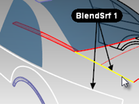
-
The edge from the adjacent surface is selected.
-
Press Enter to finish the selection for the first edge.
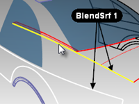
-
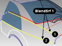
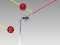
For the Select segment for second edge, select the top edge of the white side surface at the end of the edge nearest your initial pick for the first edge.
-
Press Enter to finish edge selection.
-
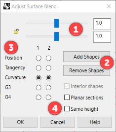
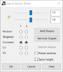
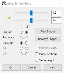
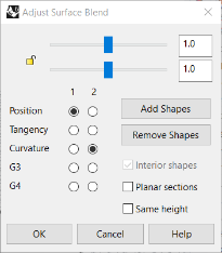
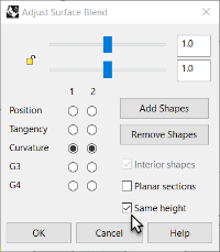
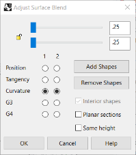
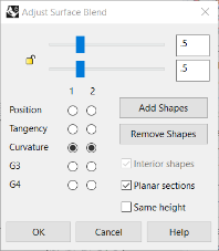
The Adjust Surface Blend dialog box with several controls appears. The next section will discuss these options.
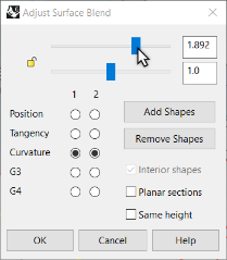
Adjust Surface Blend dialog box
|  |
|
- The sliders refer to the two default shape curves at the ends of the blend. Click the Lock icon to force both sides of the blend to be adjusted at the same time.
- This button allows the user to add shape curves. These new shape curves have adjustable handles on them exactly like the default shape curves.
*Note: *While it is sometimes useful to add shape curves, you should try to add as few as possible to achieve the shape you want. Interpolation among the shape curves is better if they are not too close together. - The radio buttons are for setting the continuity at each side of the blend; the edges are labeled 1 and 2 in the viewport.
- There are check boxes for further options. These options will be discussed later in a separate exercise.
|
To configure the dialog for the Blend, do the following:
-
Clear the check boxes for Same height and Planar sections options.
-
Make sure the Continuity buttons are set to Curvature.
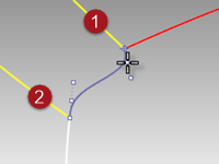
A preview of the blend surface will be visible in the viewport.
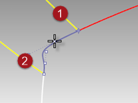
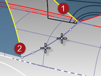
In the viewport, you will also notice a default pair of shape curves with points.
These points are called handles.The number of handles available on the shape curves varies according to the continuity settings in the dialog box.
For example, if the continuity is set to Curvature for both shape curves 1 and 2, the curves will have six points (three for each curve). If the continuity is set to Tangent for both shape curves 1 and 2, the curves will have four points (two for each curve).
-
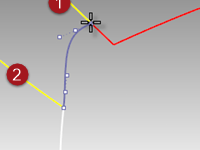
Try adjusting the handles on the shape curves. For example, at the rear of the car, make the blend sharper by moving the handles out so that they are crowded near the apex of the shape curve.
The handles can be adjusted interactively on each shape curve to change the shape of the blend.
Moving the handles changes the shape on one side of one shape curve.
Press Shift while moving the handles to force both ends of the shape curve to be adjusted together. This is useful in maintaining symmetry on the blend shape.
Press Alt while adjusting handles to rotate the handles and thus the direction of the shape curve relative to the edge.
Move the handle at an end of a shape curve to change the location of the shape curve.
Use the sliders in the dialog box to change all shape curves together.
The top slider modifies all the shape curves near the original edge #1. The lower slider modifies all the shape curves near the original edge #2.
-
Adjust the settings in the dialog box to the default value of 1.0, and click OK to make the blend surface.
Make a surface blend with All (BlendSrf 2)
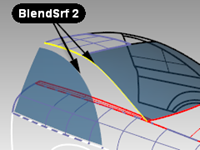
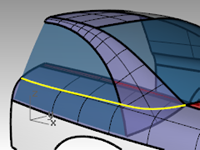
Next, we will blend between the roof rail and the side window.
-
Start the BlendSrf command (Surface menu: Blend Surface).
-
In the command-line, click the **ChainEdge **option.
-
In command-line, set options to AutoChain=No.
-
At the Select segment for first edge prompt, select an edge along the rear window of the car as marked in the file. Notice that only a small part of the edge is selected. Although the window is a single surface, the edges are split.

-
Next click the All option on the command-line to force chaining the edge fragments together.
Notice that the edge of the roof panel is also added, since the edges are contiguous and tangent to one another.
-
Press Enter to finish the first edge selection.
-
For the Select segment for second edge, select the edge at the top of the side window.
-
Press Enter to finish edge selection.
-
The Adjust Surface Blend dialog box with several controls appears.
Notice the default shape curve shows an S-shape at the lower end of the blend area.
Press the Alt key while dragging the handles to align the blend curve in a more natural way.
-
Click OK to make the blend surface.
Clean up the excess surfaces
To clean up the excess surfaces, we will trim the surfaces to each other. Since the intersections of the surfaces do not go all the way to the edges of all of the surfaces, we can make intersection curves, join them, and then extend them as needed on the surfaces.
- Start the IntersectTwoSets command (Curve menu: Curve from Objects > Intersection of Two Sets).
- As the first set of objects to intersect, select the side window and the roof blend surface you just completed. Press Enter.
- As the second set of objects to intersect with the first set, select the first blend surface you made. Press Enter.
- Join the resulting curves.
- Select the joined curve.
- Start ExtendCrvOnSrf (Curve menu: Extend Curve > Curve on Surface) and choose the lower blend surface as the surface to extend on.
- Trim the bottom of the side window, the lower end of the roof rail blend, and the side blend inside the roof and glass area.
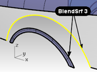
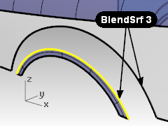
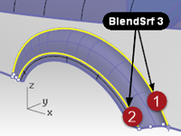
Make a surface blend (BlendSrf 3)
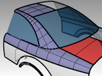
Lastly, we will blend between the wheel arch and the side of the car.
- Start the BlendSrf command (Surface menu: Blend Surface).
- For the Segment for first edge, select an edge of the wheel arch on the side of the car and Press Enter.
- For the Segment for second edge, select the other edge of the wheel arch.
- Change the continuity settings in the dialog box so that one edge has **Position **continuity (G0) and the other has **Curvature **continuity (G2), and check the Preview option.
This will allow you to have a hard edge at one of the edges.
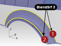
- Switch the continuity settings to the opposite edges to change the character of the blend.
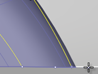
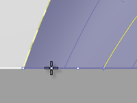
You will probably have to rotate the shape curves at both sides of the wheel arch so that they align with the bottom edge of the side.
In this case, it is easier to do this in the Front viewport.
- Press the Alt key while dragging the handles to align the blend curve to the bottom edge of the side.
- Click OK in the dialog box to make the blend surface.
On your own
Extrude the highlighted curve to create the back surface of the car. Use the same methods you used above to find the intersection curve, extend to the surface and trim.
Use Blend options
In the following exercise, we will first make a surface blend that creates a self-intersecting surface. Then we will use the surface blend options to correct the problem.
-
Open the model BlendSrf Options.3dm.
-
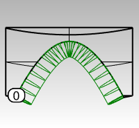
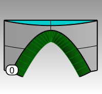
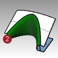
Start the **BlendSrf **command (Surface menu: Blend Surface) and select the deeply curved edges of the pair of surfaces marked 0.
-
In the dialog box, check the Same height option, and the bulge sliders are set to 1.0.
-
Click OK.
-
Zoom in on the surface you just created in the Top viewport.
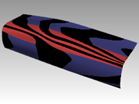
Look closely at the middle of the blend surface in this view using a wireframe viewport. Notice the blend has forced the surface to be self-intersecting in the middle. The isocurves cross each other and make a pinch or crease here.
Surface blend options
To avoid self-intersecting or pinched surfaces when creating a blend you can Adjust Blend Bulge sliders, use Same height shapes, or use the Planar sections option.
In the following examples, we will look at each of these options.
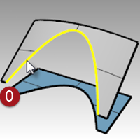
Exercise 5-6 Make a surface blend with options
-
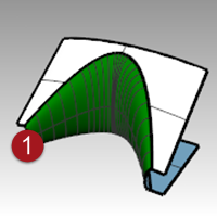
Start the BlendSrf command and select the edges of the pair of surfaces marked (1).
-
Adjust the sliders to make the bulge of the surface less than 1.
A number between 0.2 and 0.3 seems to work best.
The profiles of the cross sections at each end of the blend as well as any you may add between will update to preview the bulge. Notice that the surface is not pinched in the middle. -
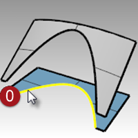
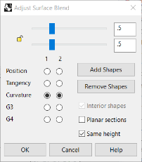
Start the BlendSrf command and select the edges of the pair of surfaces marked 2.
-
Change the **Bulge **to 0.5, but check the Same height shapes options.
The Same height shapes option overrides the tendency of the blend surface to get fatter or deeper according to how far apart the edges are. The height will be the same in the center as it is at each end. This also has the effect of making the sections of the blend push out less and therefore not cross each other out in the middle area.
-
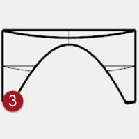
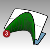
Start the **BlendSrf **command and select the edges of the pair of surfaces marked 3.
-
Pick the edges in the usual way.
Use the same bulge settings as the last pair of surfaces. -
In the dialog box, check the Planar sections option and clear the Same height option.
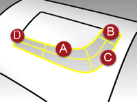
You are now asked to define which plane the sections of the surface should be parallel to. This is defined by clicking two points in any viewport.
-
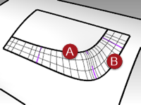
Click once anywhere in the Top viewport at A then with Ortho on, click again in the **Top **viewport B in the direction of the y-axis.
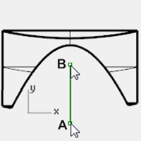
The resulting surface (3) has its isocurves arranged parallel to the plane defined in the Planar sections portion of the command. The isocurves do not intersect in the middle of the surface since they are parallel the y-axis.
Fillets, blends, and corners
In this exercise, you will see a variety of ways to make transition surfaces with FilletEdge, BlendEdge, ChamferEdge and Patch commands.
While Rhino has automated functions for making fillets, several situations take manual techniques. In this section, we will discuss making corners with different fillet radii, variable radius fillets and blends, and fillet transitions.
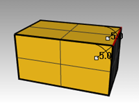
Exercise 5-7 Make a corner fillet with three different radii
-
Open the model Corner Fillet.3dm.
-
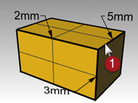
Use the **FilletEdge **command (Solid menu: Fillet Edge > Fillet Edge) to fillet edge (1) with a radius of 5mm.
-
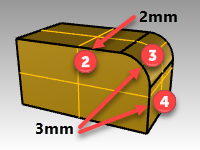
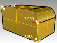
Use the FilletEdge command (Solid menu: Fillet Edge > Fillet Edge) to fillet edge (2) with a radius of 2mm, and next two edges (3) and (4) with a radius of 3mm. Enter
Note: Change the value for NextRadius to 3 before selecting the second edge.
-
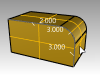
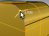
Using osnaps, drag the 3.0 radius handle to the end of the arc or vertical edge.
-
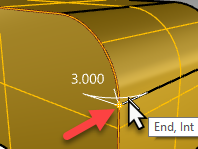
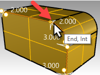
Use the AddHandle option. Set the **Current Radius **to 2.0 , the pick the new handle location at the other end of the arc, and Enter.
-
Use **Preview=Yes **to see the results of the handle edits, and then press Enter to complete the fillet.
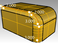
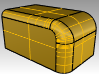
Now the fillet radius will varry from 2mm to 3mm on the arc edge.
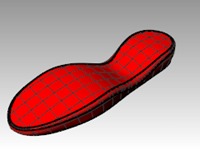
Exercise 5-8 Make a variable radius blend
- Open the model Sandal Sole.3dm.
- Use the BlendEdge command (Solid menu: Fillet Edge > Blend Edge) to make a variable radius blend on the bottom of the sole. Start with a radius of 3mm.
- Use the AddHandle option to add additional radii around the bottom of the sole.
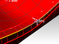
- Add another 3mm radius to the front of the sole and then add a 7mm radius to the instep on both sides.
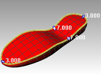
- Preview the blend and adjust the handles as needed, and then press Enter to make the blend.
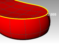
Make an edge chamfer
- Use the ChamferEdge command (Solid menu: Fillet Edge > Chamfer Edge) to make a 2mm chamfer around the top edge of the sole.
This command, like the FilletEdge command and the BlendEdge command, allow for the addition of handles with different values to create a variable distance chamfer. - Preview the chamfer and make adjustments as needed, then press Enter to make the chamfer.

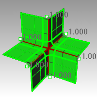
Exercise 5-9 Make a six-way fillet using a patch
- Open the model Fillet Edge.3dm.
- Use the FilletEdge command (Solid menu: Fillet Edge > Fillet Edge), with Radius=1, to fillet all the joined edges at the same time.
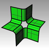
- Use the Patch command (Surface menu: Patch) to fill in the opening at the center.
- Select all six edges to define the patch.
- In the Patch Options dialog box, check the Adjust Tangency and Automatic Trim options.
- Change the Surface U and V Spans to 10, and the Stiffness to 2.
Note: When the area to fill has more than four edges, the Patch command works better than the NetworkSrf command.