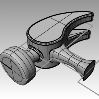
In this exercise you will use many of the commands and techniques that you’ve learned in the previous sessions. Commands like Circle, Arc, Revolve, Sweep1, Sweep2, BooleanDifference, Trimand more will be need to complete this model. You can also consider rendering it or preparing it for 3-D printing.
Some models require more attention to detail. This is an example of a model that requires precise modeling techniques. This exercise also requires a number of different surface creation techniques. The technical drawing is included to help you create a very precise model.
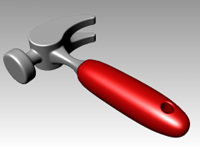
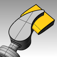
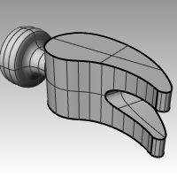
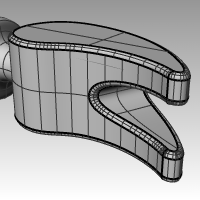
Exercise 10-10 The Hammer
-
Open the model Hammer.3dm. The following layers have been created: Construction Lines, Curves, Handle, Tang, Head, Hole, Cutout, and Claw. Use the appropriate layer when constructing the model..
-
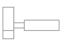
In the Top viewport, draw outlines for the hammer. Drawing outlines helps while drawing the curves. You can either draw lines, polylines, or rectangles to create the outlines. Use the dimensions on the technical drawing to get accurate outlines.
Note: The Hammer model contains an existing layer with the construction lines for the this model already created called Construction Lines. There is a sublayer with centerlines that should also be helpful. Turn these layers on to speed up the exercise. Or create your own construction geoemtry for additional practice and a more realistic approach.
- All Filets are 2mm, typical, unless otherwise noted.
Add the Picture
In the Front view use the Picture commands to attach the Hammer_mm.png. It will make it easy to reference the dimensions while modeling.
- Make the Front viewport current.
- On the Surface menu, under Planar click Picture.
- In the **Open Bitmap **dialog, navigate to your class files folder and select the Hammer_mm.png.
- Pick the **First corner of picture **and then the **Other corner **to get the length of the image.
- Highlight the picture and using the Gumball, move the surface back behind the curves.
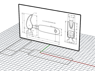
- Highlight the picture and in the Properties panel, pick the Materials page.
- Under the Picture section, drag the Object transparency slider to 50%.
This will fade the picture, and make it easier to see the object lines that you will add next.
Create the claw
When modeling the shape of the claw, you will use circles, arcs, and curves. You can trim the circles and arcs and then join them together to create a closed curve. You can rebuild the curve and adjust the control points to get a more sculptural shape.
-
Change to the Curves layer.
-
In the Top viewport, draw a curve defining the shape of the claw.
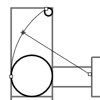
You can use a free-form curve or use a combination of arcs and circles that are trimmed and joined to create the curve. Following is a systematic approach to creating the curve for the claw part of the hammer using arcs and circles.
Start by drawing two circles. -
Use the Circle command (Curve menu > Circle > Tangent to 3 curves) to create a circle at the lower end of the claw.
Draw the circles tangent to the construction geometry -
Use the Circle command (Curve menu > Circle > Tangent, Tangent, Radius) to create a circle at the upper end of the claw that is tangent to the upper right corner with a 4 mm radius.
Draw the circles tangent to the construction geometry.
-
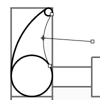
Use the Arc command (Curve menu > Arc > Tangent, Tangent, Radius) to create arcs that are tangent to the two circles.
-
Use the Trim command (Edit menu > Trim) to trim the inside part of the circles.
-
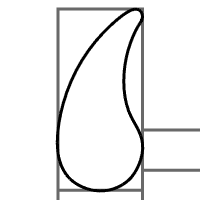
Use the Join command (Edit menu > Join) to join the arc segments.
-
Make the Claw layer current.
-
Select the joined segments.
-
Use the ExtrudeCrv command (Solid menu > Extrude Planar Curve > Straight) to extrude the curve on both sides of the construction plane.
Create the head
- Make the Curves layer current.
- Use the Curve command (Curve menu > Free-form > Control Points) to create the curve for the cross-section of the head.
Make sure the curve intersects the claw part. This makes joining the two pieces easier.
- Make the Head layer current.
- Use the Revolve command (Surface menu > Revolve) to revolve the curve.
Use the midpoint of the construction line for the revolve axis.
- Save your model.
Add the head to the claw part
- Use the BooleanUnion command (Solid menu > Union) to join the head with the claw.
If the result is not correct, flip the normal of the head surface with the Dir - command. The normal of the head surface should be towards out.
- Use the FilletEdge command (Solid menu > Fillet Edge > Fillet Edge) fillet the intersection between the head and the claw.
- Save your model.
Create slot for the claw part of the hammer
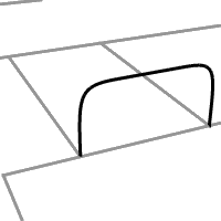
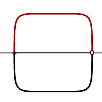
- Use the Curve command (Curve menu > Free-form > Control Points) to draw a curve for the slotted part of the claw.
Make sure the curve is symmetrical. - Use the Line command (Curve menu > Line > Single Line) to draw a line between the endpoints.
- Use the Join command (Edit menu > Join) to join the curve and the line.
- Drag the closed curve closer to the claw.
- Use the Rotate command (Transform menu > Rotate) or gumball to rotate the curve to align more closely with the curve of the claw.
- Make the Claw layer current.
- Use the ExtrudeCrv command (Solid menu > Extrude Planar Curve> Straight) to extrude the curve through the claw.
- Save your model.
- Use the BooleanDifference command (Solid menu > Difference) to subtract the slot from the claw.
- Use the FilletEdge command (Solid menu > Fillet Edge) to make the fillets around the top and bottom of the claw, and the slot.
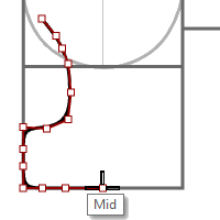
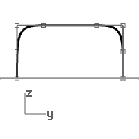
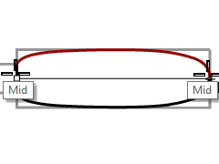
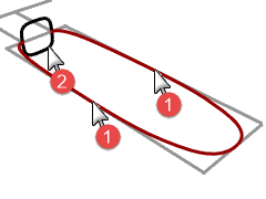
Create the shape curve for the tang and the handle
Create the shape curve for the tang in the **Right **viewport. This curve will also be used for the handle.
- Make the Curves layer current, and turn on Ortho.
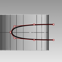
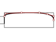
- Use the Curve command (Curve menu > Free-form > Control Points) to draw a curve for the upper cross-section of the tang.
Make sure the curve is symmetrical.
- Use the Mirror command (Transform menu > Mirror) to create the other curve.
- Use the Join command (Edit > Join) to join the curves.
- Save your model.
Create the tang
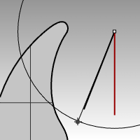
- Use the InterpCrv command (Curve menu > Free-form > Interpolate Points) to draw one of the curves for the tang of the hammer.
Make sure that it intersects the claw.
- Use the Mirror command (Transform menu > Mirror) to create the other curve.
- Make the Tang layer current.
- Use the Sweep2 command (Surface menu > Sweep 2 Rails) to make the surface.
- Use the Cap command (Solid menu > Cap Planar Holes) to make the tang a closed polysurface.
- Save your model.
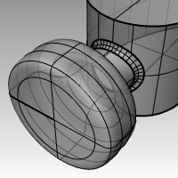
Finish the hammer head
- Select the tang and the claw.
- Use the BooleanUnion command (Solid menu >Union) to join the tang with the claw and the head.
- Use the FilletEdge command (Solid menu> Fillet Edge) to make the fillets at the intersection between the tang and the claw.
The edge has a round on it. - Save your model.
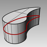
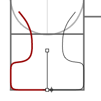
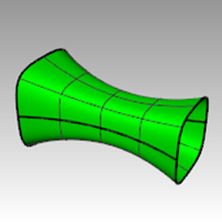
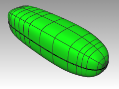
Create the handle
-
Make the Curves layer current.
-
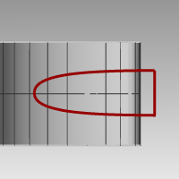
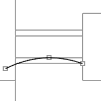
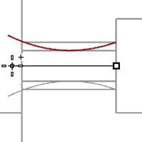
Use the Curve command (Curve menu > Free-form > Control Points) to draw a curve for the top edge of the handle.
Make it start at the endpoint of the tang profile curve and end on the center line.
-
Use the Mirror command (Transform menu > Mirror) to make the other half.
-
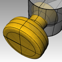
Make the Handle layer current.
-
Use the Sweep2 command (Surface menu > Sweep 2 Rails) to make the surface using the tang curve as the profile curve.
A surface is created. -
Use the Cap command (Solid menu > Cap Planar Holes) to cap the open end.
-
Save your model.
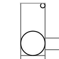
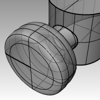
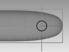
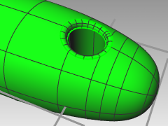
Create the hole for the handle
- Use the Circle command (Curve menu > Circle > Center, Radius) to make a circle 25mm from the end of the handle.
You may have to draw a construction line to help you position the circle.
- Use the ExtrudeCrv command (Solid menu > Extrude Planar Curve > Straight) to extrude the curve on both sides of the construction plane.
Make sure the extrusion intersects both sides of the handle.
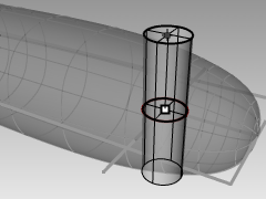
- Use the BooleanDifference command (Solid menu > Difference) to subtract the hole from the handle.
- Use the FilletEdge command (Solid menu> Fillet Edge) to make the fillets at the edges of the hole.
The edges have rounds on them.
- Save your model.
