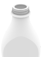
Some models require more attention to detail. This is an example of a model that requires precise modeling techniques. This exercise also requires a number of different surface creation techniques.
The technical drawing is included to help you create a very precise model.
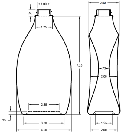
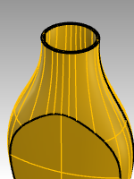
Creating a squeeze bottle
- Open model Squeeze Bottle.3dm.
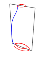
- Use the pre-drawn rectangle to create a circle, an ellipse, and a profile curve.
These curves will be used to generate the surfaces of the bottle.
Note: A set of these curves is already included in the model as **Bottle_curves **and Path_curves. These layers are sublayers of a layer named Curves.
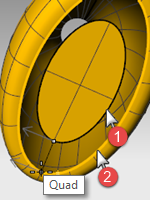
- Make another (smaller) ellipse that will be used for the concave part at the bottom of the bottle.
- Move this ellipse vertically .25 units.
Create the surfaces for the bottle
- Change to the Bottle_surface layer and turn off the Reference layer.
- Select the small ellipse.
- Use the PlanarSrf command (Surface > Planar Curves) to make a flat surface.
**Bottle_surface **is a sublayer of Surfaces
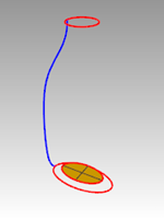
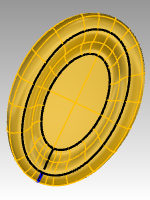
- Select the large ellipse and the circle.
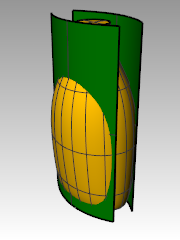
- Start the Sweep2 command (Surface > Sweep 2 Rails).
The pre-selected ellipse and circle will be the rails for the sweep. - For the Select cross section curves, choose the profile curve, and then press Enter.
- In the Sweep 2 Rail Options dialog box, click Do not change cross sections. This option will creates the sweep without altering the cross-section curves.
Also check Closed sweep, and then click OK.
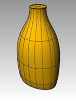
Create a blend surface for the bottom of the bottle
- Hide the rail and profile curves.
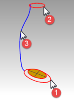
- Start the BlendSrf command (Surface > Blend Surface).
- For the Segment for first edge, select the edge of the ellipse surface, and then press Enter.
- For the Segment for second edge, select the edge of the bottle surface, and then press Enter.
- For the Drag seam point to adjust, move the seam points so that the align with each other, and press Enter.
- In the Adjust Surface Blend dialog, preview the sweep.
Make any adjustments that are necessary and then click OK. - Join the three surfaces.
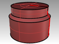
Hint In the **Display **panel, you can enable Object settings and Color Backfaces in your current display mode. Pick a **Backface color **like cyan that will easily identify the normal direction of the surface and any openings in your polysurface.
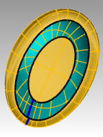
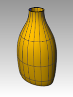
Shaded displaymode image with a backface color set to cyan
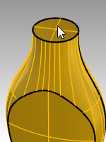
Cap the top
If you close the bottle, thereby creating a solid, Rhino can calculate the bottle’s volume. If you were creating this bottle in real life, knowing the volume would be important. Normally, a bottle would have to be designed to hold a specified volume.
If the edges of the remaining open surfaces are planar curves, you can use the **Cap **command to close them. The open edges on the bottle are the top circular shape and the bottom elliptical shape, and they are planar.
Cap the top and bottom
 3. Select the surface.
4. Use the Cap command (Solid menu > Cap Planar Holes) to close the holes.
3. Select the surface.
4. Use the Cap command (Solid menu > Cap Planar Holes) to close the holes.
Making the Surface for the Label
In this part of the exercise, you will create custom surfaces to trim an area on each side of the bottle for a label. The new surface will have curvature in only one direction.
Note: A set of these curves is already included in the model on layer Label_Surface_Curves, a sublayer of the Curves layer.
Create the trimming surface
-
Make the Label_Surface_Curves layer current.
-
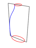
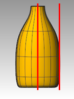
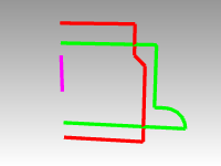
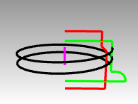
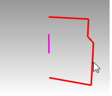
In the Front viewport, draw two lines.
One line in the middle and one on the side.
Make sure the lines extend a little below and above the height of the bottle.
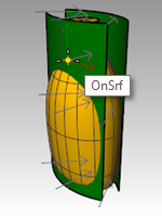
-
In the Right viewport, Move the lines so that they will intersect the bottle, like the illustration on the right.
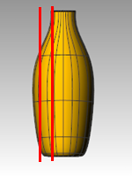
-
Mirror the line on the side to the other side of the bottle.
These lines will be used to create a cutting surface for the flat side of the bottle. -
Make the Label_Surface layer current.
-
Select the three curves you just created.
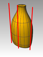
-
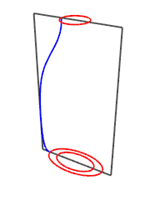
Use the Loft command (Surface menu > Loft) to make the cutting surface.
-
In the Loft Options dialog, clear the Closed loft check box, and click OK.
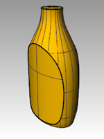
A lofted surface intersects the bottle.
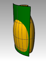
-
Mirror the surface to the other side of the bottle.
-
Save your model.
Remove the surface from the bottle
-
Change to the Bottle Srf layer.
-
Use the Dir command (Analyze menu > Direction) to check the surface normal direction.
Flip the normals if necessary.
The normals should be pointing toward the center of the bottle. -
Select the bottle.
-
Use the BooleanDifference command (Solid menu > Difference) to subtract the two lofted surfaces from the bottle.
-
To create a hollowed out shell from a solid polysurface, like this bottle, use Shell.
At the command prompt, type Shell. -
Pick the top surface as the surface to remove.
-
Use a shell thickness of .05mm. You may experiment with other shell thicknesses.
-
Enter to Shell the bottle.
-
Use the **What **command to check the geometry. After the Shell, it should still be “valid and closed polysurface.”
If not, **Undo **and use a thinner shell. Use the **ShowEdges **with the Nakedoption to determine where the opening have occurred.
**Shell **only operates on simple, solid, manifold polysurfaces. For more information on this command view the ShellHelp topic. -
Turn on the Bottle Srf layer
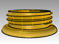
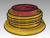
Create the bottle’s top
To create the bottle top, you are going to revolve a profile curve to create the surface.
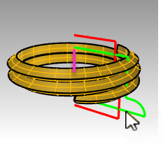
Create the thread curve
-
Turn on the Top_Detail_curves layer and make the **Neck_Curves **sublayer current.
-
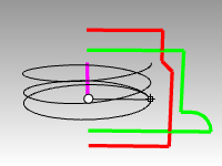
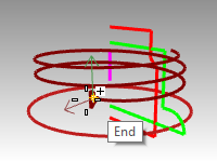
On the **Curve **menu, pick Helix.
-
Pick the **AroundCurve **option in the Command line.
-
Pick the magenta curve as the axis for the helix.
-
In the Command line, set Helix options:Set Mode=Turns,Turns=2 and ReverseTwist=No.
-
In the **Front **viewport, snap the radius to the green profile curve.
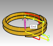
Extend and scale the thread curve
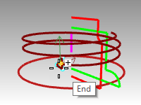
To allow the thread to ramp smoothly at each end instead of starting and stopping abruptly, here you will extend the helix and scale it inward towards the middle of the bottle’s neck.
-
On the **Curve **menu, pick Extend Curve and Extend Curve.
-
Enter to dynamic extend.
-
Pick on one end of the helix.
-
Set the extension Type=Smooth or Type=Natural.
-
Type **.5, **and Enter to extend the curve smoothly .5 units.
-
Click on the other end of the curve and repeat the .5 unit extension. The command keeps running after the first extension so you do not need to start it again. Enter or Esc after the second extension to end the command.
-
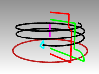
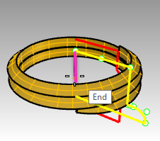
Select the red and green curves. From the **Edit **menu, pick **Visibility **and Hide.
(They will be turned back on with the **Show **command later in this exercise.) -
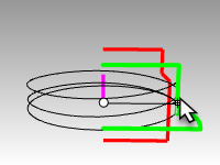
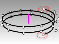
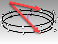
Turn on control points for the helix with the **PointsOn **command.
-
Select the control points at both ends.
-
From the **Transform **menu, pick **Scale **and **Scale2D **command.
-
In the **Top **viewport, set the base of the scale to the CPlane origin by typing in 0 and Enter.
-
For the scale factor, type .85 .
The location of the end points will scale towards the origin, and the ends of helix will be reset.
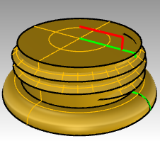
Orient the curve
Now you will place the thread profile on our newly extended helix.
-
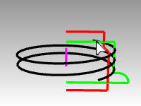
On the **Transform **menu, pick **Orient **and the **OrientOnCrv **command.
-
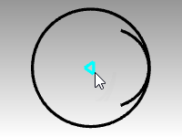
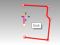
In the **Top **viewport, select the small triangle at the origin as the object to orient, .
-
In the **Top **viewport, set the base point at the origin by typing 0 and Enter.
This will be the point, in the middle of the triangle, that is mapped to the orientation curve. -
Select the helix as the Orientation curve very close to one of the ends.
You will only need one curve oriented at one of the ends of the helix.
An **End point **osnap will be used here to snap exactly at the end of the helix. -
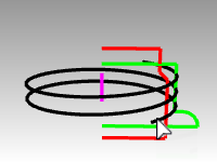
You will see the preview of the triangle floating with the cursor along the helix. Set the options **Copy=Yes **, click the **Perpendicular **.
-
Next click **XFlip=Yes **only if the point of the triange is not oriented to the outside of the helix.
**Note **With **XFlip=Yes **the curve to orient flips itself perpendicular to the curve on the axis you specify.
Toggle the Xflip setting and choose the one that previews the point of the triangle oiented to the outside of the helix.
| XFlip required. | Desired orinetation. |
-
Click at the the end of the helix curve to place the triangle.
-
Preview the result in the Rhino viewport and Enter .
Now everything is in place to create the thread surfaces.
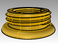
Sweep the curve
Now you will place the thread profile on our newly extended helix.
- Make the **Neck_surface **layer current.
- From the **Surface **menu, pick the **Sweep1 **command.
- Select the helix as the path curve, the triangle at one end as the shape curve.
- With the **Perspective **view active, set the sweep style to **Roadlike **to ensure that the profile maintains its orientation correctly for a vertical thread as it sweeps around.
- Make any adjustments that are necessary and then click OK.
- Highlight the swept surface and from the **Solid **menu pick Cap Planar Holes. Cap makes the resulting sweep closed at the open ends and solid.
Union the neck
To make the neck itself, you will revolve the two vertical curves to create solids and combine them into a closed solid with two Boolean operations.
-
From the **Edit **menu, pick **Visibility **and Show.
-
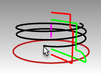
From the **Surface **menu, pick **Revolve **.
-
Select the green vertical curve as the curve to revolve.
-
Set the axis to the origin 0 of the Top CPlane and press Enter to use the CPlane z-axis direction. Or pick the end points of the magenta line, indicating the revolve axis.
-
Pick **Full circle **option in the Command line.
-
From the **Solid **menu, pick BooleanUnion. Select the thread solid and the revolved solid.
-
Hide the threaded neck which resulted from the BooleanUnion.
Difference the opening
-
Make the Plug layer current.
-
Select the red vertical curve.
-
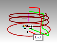
From the **Surface **menu, pick Revolve.
-
At the Start of revolve axis type 0 and Enter.
-
In the Top CPlane and press Enter to use the default option of the CPlane z-axis direction.
Option: Pick the end points of the magenta line, indicating the revolve axis.
-
Pick **Full circle **option in the Command line.
-
**Show **the threaded neck.
-
From the **Solid **menu, pick BooleanDifference. Select the thread solid and Enter. Next pick the last revolve and Enter
The revolved surface is not subtracted from the solid thread, resulting in a new solid neck for the bottle.
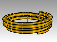
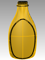
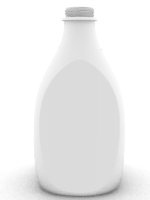
The whole bottle
Now you will put both pieces together.
- Turn on the Bottle Srf layer and make it current.
- From the **Solid **menu, pick BooleanUnion. Select the bottle solid and the neck solid. Press Enter to union them into one closed solid.
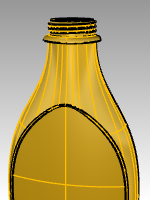
Fillet the bottle
Soften the transition between the label surface and the bottle.
-
From the **Solid **menu, pick **Fillet Edge **and Fillet Edge.
-
Type .25 as the fillet radius and Enter.
-
Select the curve that defines the transition between the label surface and the bottle.
-
Enter twice to exit the command.
-
Repeat for the other side of the bottle.
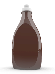
Rendering the bottle
Render the bottle with plastic materials. Place lights.
Adding a decal
Use Decals to attach a label to the front of the bottle.
-
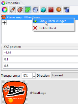
In the Properties panel, on the Decal page, click the “+”.

-
Navigate to and select image file,
tHbestLogo.png. -
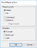
On the Decal Mapping Style dialog, accept the default **Mapping style **of **Planar **and **Direction **of **Forward **by picking OK.
-
In the **Front **viewport, pick two diagonal points to locate and size the decal. This is easier with osnaps disabled.

-
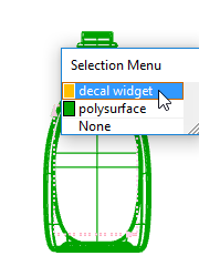
Right-click on the **tHbestLogo.png **decal in the Decal panel, and pick Show the Decal Widget.
-
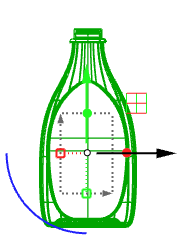
On the Status Bar, turn on the **Gumball **control. With the Gumball on, you can move, re-size, and rotate the decal with the gumball control.
Refer to the **Rhino Help **for additional details on the Decalfeature.

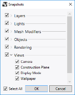
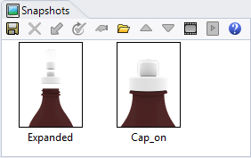
On your own
- Use the **SnapShot **command to save and restore configurations for the bottle and caps. Refer to the **Rhino Help **for details on the **SnapShot **command.