This text is largely based on a Discourse post by Rhino user and teacher Lagom and enhanced with illustrations and examples.
Curves
In any CAD software, the accuracy and quality of your primary curves (“splines” or “sections” or “sketches”) is paramount, because they determine the quality of your primary surfaces, and your primary surfaces determine how well your secondary surfaces, and tertiary surfaces (blends, fillets) will work (think of a tree: “trunk > branch > twig > leaf” relationship).
Single span curves
Always try to use
![]() InterpCrv
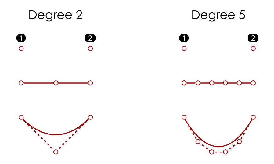
to draw single-span curves with Degree set to 2 or 5. Place the start and end points, then shape the curve by moving the 1 (degree 2) or 4 (degree 5) free controlpoints (CPs), or match them to other curves/surfaces directly.
InterpCrv
to draw single-span curves with Degree set to 2 or 5. Place the start and end points, then shape the curve by moving the 1 (degree 2) or 4 (degree 5) free controlpoints (CPs), or match them to other curves/surfaces directly.
Alternatively, use
![]() Curve
with Degree set to 2 or 5. Place the 3 (degree 2) or 6 (degree 5) CPs, then finalize the shape by moving them, or match it to other curves/surfaces directly.
There is a case when a degree 3 curve can be useful - for constructions where a single-span curve must “take off” with G2 and end in a point with G0 continuity.
Curve
with Degree set to 2 or 5. Place the 3 (degree 2) or 6 (degree 5) CPs, then finalize the shape by moving them, or match it to other curves/surfaces directly.
There is a case when a degree 3 curve can be useful - for constructions where a single-span curve must “take off” with G2 and end in a point with G0 continuity.
![]() BlendCrv
is ideal to create G1 (tangent) or G2 (curvature) continuous single span curves between existing curves and/or surface edges, allowing you to fine-tune their shape interactively (use the Show curvature option while doing so). Use the
key to change the contact angle. Use the
key to adjust symmetrically on both ends, while moving the G1 and G2 handles on one end.
BlendCrv
is ideal to create G1 (tangent) or G2 (curvature) continuous single span curves between existing curves and/or surface edges, allowing you to fine-tune their shape interactively (use the Show curvature option while doing so). Use the
key to change the contact angle. Use the
key to adjust symmetrically on both ends, while moving the G1 and G2 handles on one end.
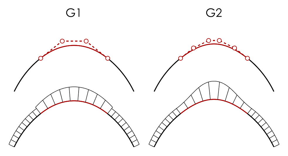
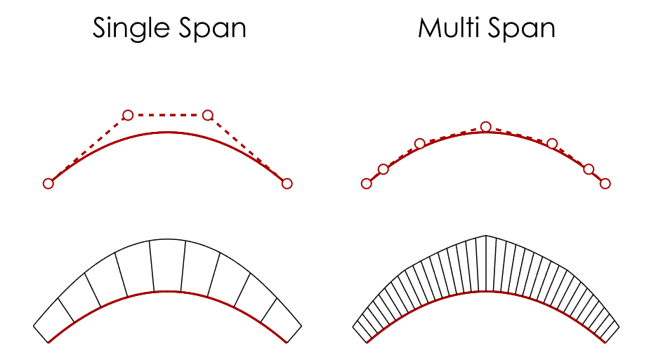
The advantage of using single span curves is that the curve is perfectly curvature continous internally. Curves that are multi-span, will have less fluent curvature transitions internally. When building surfaces from these curves, curvature irregularities between spans can become visible in the manufactured end result. The following image shows a single span degree 3 curve (4CPs) and a multispan degree 3 curve (7 CPs). Notice the G3 discontinuities in the multispan curve.
Circles
By default,
![]() Circle
creates a rational degree 2 curve with kinks (multi-knots). Draw circles with the Deformable option selected, Degree set to 5, and Point Count to 8. For ellipses, just non-proportionally scale (
Circle
creates a rational degree 2 curve with kinks (multi-knots). Draw circles with the Deformable option selected, Degree set to 5, and Point Count to 8. For ellipses, just non-proportionally scale (
![]() Scale1D
) such a circle.
Scale1D
) such a circle.
Editing Curves
![]() InsertKnot
or
InsertKnot
or
![]() InsertControlPoint
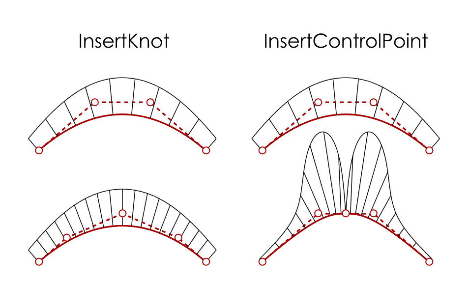
can be used if you need an extra CP while shaping a curve. Both add a span and CP to the curve. InsertKnot adds a CP but keeps the shape of the curve the same, InsertControlPoint adds a CP and alters the shape of the curve. The following image shows the result of adding a knot or a CP at the middle of a degree 3 single span curve.
InsertControlPoint
can be used if you need an extra CP while shaping a curve. Both add a span and CP to the curve. InsertKnot adds a CP but keeps the shape of the curve the same, InsertControlPoint adds a CP and alters the shape of the curve. The following image shows the result of adding a knot or a CP at the middle of a degree 3 single span curve.
![]() RemoveKnot
removes a span and CP from the curve. The curve’s degree remains unchanged in both cases.
RemoveKnot
removes a span and CP from the curve. The curve’s degree remains unchanged in both cases.
Alternatively, use
![]() ChangeDegree
to a higher value with the Deformable option to add CPs to a curve. The number of spans and the curve’s shape remains unchanged. Caveat: without the Deformable option selected, more CPs will be created. Use the
ChangeDegree
to a higher value with the Deformable option to add CPs to a curve. The number of spans and the curve’s shape remains unchanged. Caveat: without the Deformable option selected, more CPs will be created. Use the
![]() CurvatureGraph
tool to see what happens.
CurvatureGraph
tool to see what happens.
![]() Rebuild
can be used to change a curve’s degree and number of CPs, but it is generally not recommended (messy CP structure).
Rebuild
can be used to change a curve’s degree and number of CPs, but it is generally not recommended (messy CP structure).
To flatten (planarise) one or more non-planar curves, select all CPs, click the Gumball X, Y or Z scaling icon, and type 0 into the value field. An alternative is using
![]() SetPt
macros, which can be assigned to aliases. These allow you to pick a point in the direction you are flattening. For example:
SetPt
macros, which can be assigned to aliases. These allow you to pick a point in the direction you are flattening. For example:
| Alias | Command Macro |
|---|---|
| sx | '_-setpt x=yes y=no z=no |
| sy | '_-setpt y=yes z=no x=no |
| sz | '_-SetPt z=yes x=no y=no |
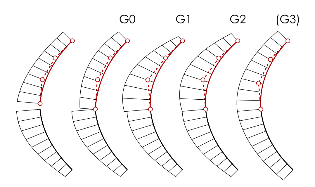
Curve Continuity
- Use
 Match
to make a curve G0 (position), G1 (tangent) or G2 (curvature) continuous to another curve.
Match
to make a curve G0 (position), G1 (tangent) or G2 (curvature) continuous to another curve. - Use the SurfaceEdge option to match to any location on any surface edge, and the subsequent Perpendicular to edge option for a perfect “T” alignment.
Although currently you cannot match curves with torsional continuity (G3) in Rhino, with help of point manipulation and curvature graph a close to G3 match can be made. Shown here is a match of the upper curve to the lower curve, while the end of the matched curve is preserved (positional).
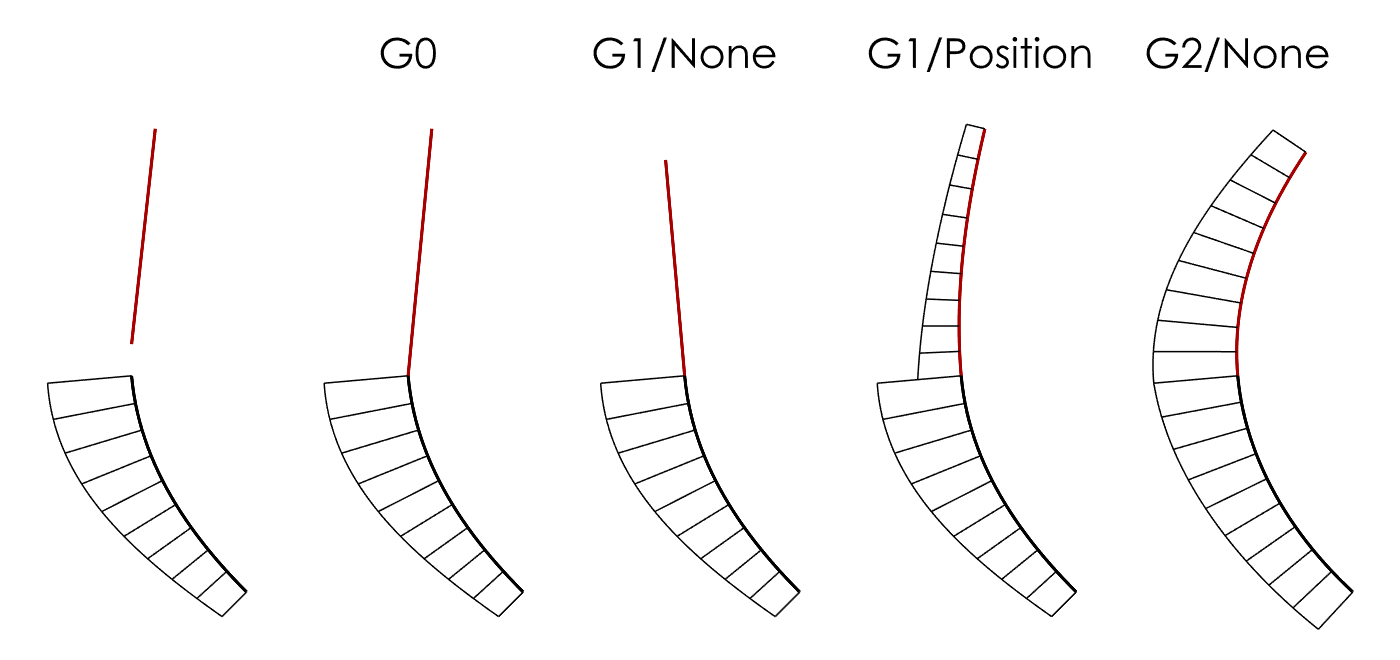
EndBulge Curves
Use
![]() EndBulge
with the Tangency or Curvature option to manipulate the 2nd (G1) CP and/or 2nd and 3rd (G2) CPs to adjust the curve’s shape without losing the continuity previously established by matching. Activate
EndBulge
with the Tangency or Curvature option to manipulate the 2nd (G1) CP and/or 2nd and 3rd (G2) CPs to adjust the curve’s shape without losing the continuity previously established by matching. Activate
![]() CurvatureGraph
beforehand.
CurvatureGraph
beforehand.
Evaluating Curves
- Use
 CurvatureGraph
to examine a curve’s curvature while modeling, and to check for internal G3 discontinuities.
CurvatureGraph
to examine a curve’s curvature while modeling, and to check for internal G3 discontinuities. - Use
 GCon
to evaluate the G0 (position), G1 (tangent) or G2 (curvature) continuity between curves numerically. G0 continuity between curves is essential for building watertight (no naked edges) surface models.
GCon
to evaluate the G0 (position), G1 (tangent) or G2 (curvature) continuity between curves numerically. G0 continuity between curves is essential for building watertight (no naked edges) surface models.
Curve Do’s
Use single span curves whenever possible. Less spans/CPs mean that a curve’s curvature is easier to control. Also, simple curves make for simple surfaces.
Curve Don’ts
Don’t
![]() Join
curves (semi-circles joined to lines to build a “pill shape” is a classic), because joining creates kinks at the join location. When you use such curves to build surfaces, it can make subsequent operations unnecessarily difficult. Any design can be perfectly modeled without joining curves.
Join
curves (semi-circles joined to lines to build a “pill shape” is a classic), because joining creates kinks at the join location. When you use such curves to build surfaces, it can make subsequent operations unnecessarily difficult. Any design can be perfectly modeled without joining curves.
Surfaces
Editing Surfaces
By default, surfaces show two isocurves (one in the U and one in the V direction), if it is a single span surface. Set Isocurve Density to 0 in Properties to display only isocurves generated from a curve’s knots, or from an adjacent surface’ knots. In Rhino Options, General you can set the default to 0 as well if you prefer.
- You can use
 RemoveKnot
to remove U and/or V isocurves to reduce surface complexity, and then use
RemoveKnot
to remove U and/or V isocurves to reduce surface complexity, and then use
 ChangeDegree
.
ChangeDegree
. -
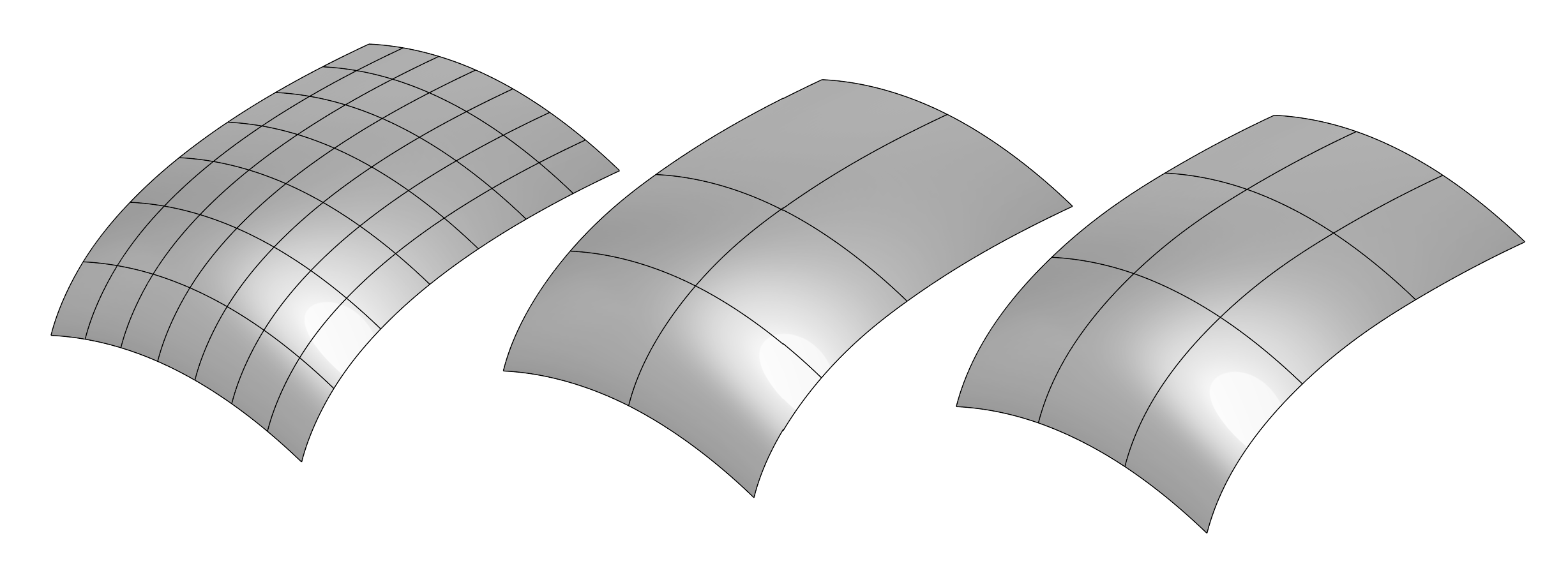
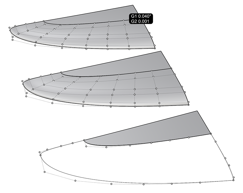
 FitSrf
fits a surface based on set tolerance. This can be helpful to reduce the number of spans by changing the degree and choosing a tolerance. A Value of 0 will use your file’s absolute tolerance setting.
In this example, a dense surface patch (left) was Refit (middle) and Rebuilt (right) with roughly the same end tolerance result. You can see that FitSrf is more adaptive to the surface’ curvature as to where it places additional spans, which means that given a certain tolerance, it is capable of creating a simpler surface than Rebuild.
FitSrf
fits a surface based on set tolerance. This can be helpful to reduce the number of spans by changing the degree and choosing a tolerance. A Value of 0 will use your file’s absolute tolerance setting.
In this example, a dense surface patch (left) was Refit (middle) and Rebuilt (right) with roughly the same end tolerance result. You can see that FitSrf is more adaptive to the surface’ curvature as to where it places additional spans, which means that given a certain tolerance, it is capable of creating a simpler surface than Rebuild.
- To fine-tune a surface’ shape, use
 DragMode
with the UVN option to adjust individual CPs. Set the Gumball to Align to Object. Adjust
DragMode
with the UVN option to adjust individual CPs. Set the Gumball to Align to Object. Adjust
 DragStrength
if you want finer mouse control. You can also use the arrow keys on the keyboard for U and V movement, where for N movement, use
/
(On certain laptops :
plus
/
). Don’t forget to reset DragMode to normal by selecting the UVN option again after you’re done (it’s a toggle)!
DragStrength
if you want finer mouse control. You can also use the arrow keys on the keyboard for U and V movement, where for N movement, use
/
(On certain laptops :
plus
/
). Don’t forget to reset DragMode to normal by selecting the UVN option again after you’re done (it’s a toggle)! - Alternatively, use the traditional
 MoveUVN
tool to improve continuity.
MoveUVN
tool to improve continuity. - To clean up a messy surface control point structure before matching for G1 or G2 continuity, this script by Pascal Golay is a life-saver, allowing you to planarise CPs along a surface’ U or V direction from any viewpoint. Save the script and run it from an alias (keyboard shortcut). For more info on running scripts, see this guide.
- In all cases, when modifying using controlpoint editing or fitting, check the continuity between your surfaces with
 EdgeContinuity
Cutting Surfaces
- Use
 Trim
to cut off part of a surface with curves or other surfaces. The cut-off part is still “there”; it is just not displayed. Display the CPs
Trim
to cut off part of a surface with curves or other surfaces. The cut-off part is still “there”; it is just not displayed. Display the CPs
 PointsOn
or keyboard shortcut
to see for yourself. See this page for more information about trimmed surfaces.
PointsOn
or keyboard shortcut
to see for yourself. See this page for more information about trimmed surfaces. - To cut a surface with another surface, while retaining the parts of both, use
 Split
instead of Trim.
Split
instead of Trim. - To cut a surface in its U or V direction, use
Split
with the Isocurve option enabled. You can split freely or snap. The Shrink option creates two natural surfaces (display the CPs with/without Shrink and move one of the surfaces away to see what the difference is).
- Use
 ExtendSrf
with a negative value and the Smooth and Merge options on to shorten a surface instead of using Split.
ExtendSrf
with a negative value and the Smooth and Merge options on to shorten a surface instead of using Split. -
 RefitTrim
converts a surface with one trimmed edge (an edge-to-edge trim only) to an untrimmed (natural) surface, but it might deviate considerably from the original, so pay attention. Use
RefitTrim
converts a surface with one trimmed edge (an edge-to-edge trim only) to an untrimmed (natural) surface, but it might deviate considerably from the original, so pay attention. Use
 MatchSrf
afterwards if previously achieved continuity to other surfaces must be re-established.
MatchSrf
afterwards if previously achieved continuity to other surfaces must be re-established. - Use
 RebuildEdges
to “repair” trimmed edges that prevent proper matching.
RebuildEdges
to “repair” trimmed edges that prevent proper matching.
Surface Continuity
Use
![]() MatchSrf
to make a surface G0 (position), G1 (tangent) or G2 (curvature) continuous to another. You can only match untrimmed (natural) edges of a surface, but you can match to another surface’ trimmed edge. Click near the same end on both edges, so that the surface doesn’t flip. Always check with
MatchSrf
to make a surface G0 (position), G1 (tangent) or G2 (curvature) continuous to another. You can only match untrimmed (natural) edges of a surface, but you can match to another surface’ trimmed edge. Click near the same end on both edges, so that the surface doesn’t flip. Always check with
![]() EdgeContinuity
; don’t rely on the
EdgeContinuity
; don’t rely on the
![]() Zebra
display mode only.
Zebra
display mode only.
Recommendations when using
![]() MatchSrf
:
MatchSrf
:
- Match equal degree surfaces: Use default options.
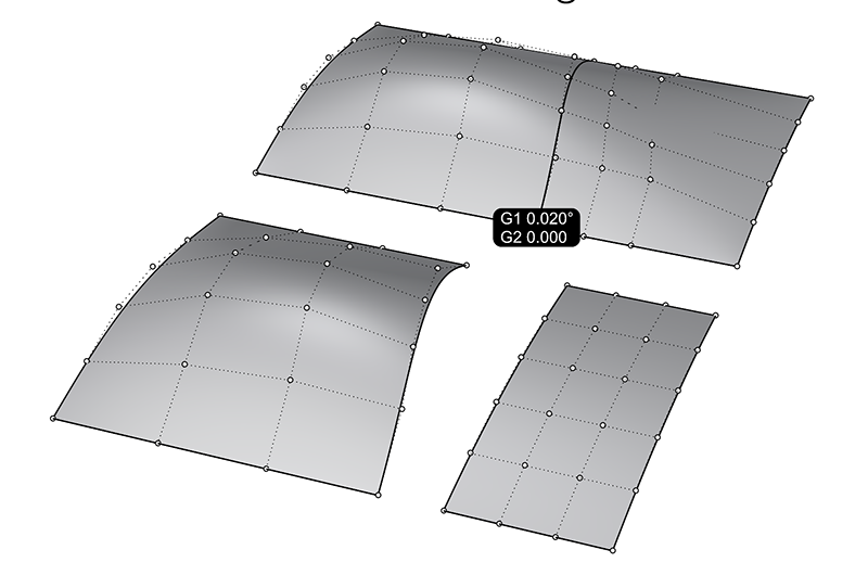
- Match a lower degree surface to a higher degree surface: Raise its degree with
ChangeDegree
before matching. The surfaces shown at the top in the image below are matching well after matching its degree to the target surface before running MatchSrf.
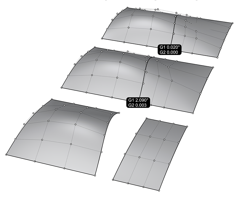
- Match a higher degree surface to a lower degree surface: Use default options.
- Match a surface to a trimmed edge: Use the options Match edges by closest points and Preserve isocurve direction.
- Match a shorter surface edge to a longer surface edge (partial match): Use the option Match edges by closest points.
-
Match a surface while keeping its contact angle: Use the option Preserve isocurve direction.
-
Match a surface edge onto another surface: Use the On Surface option.
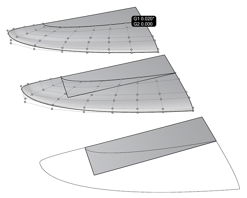
- The Average surfaces option equally changes both surfaces.
- The Refine match option often produces surfaces with far too many isocurves. Instead, turn on EdgeContinuity to find out where the largest deviation is, and insert a knot at that location with
 InsertKnot
(try the Midpoints option) and match again. If you match with History enabled, the result of the analysis will update automatically after inserting a knot.
InsertKnot
(try the Midpoints option) and match again. If you match with History enabled, the result of the analysis will update automatically after inserting a knot.
To improve the result of MatchSrf, use
![]() DragMode
with the UVN option to adjust individual CPs. Set the Gumball to Align to Object.
Adjust
DragMode
with the UVN option to adjust individual CPs. Set the Gumball to Align to Object.
Adjust
![]() DragStrength
if you want finer mouse control. You can also use the arrow keys on the keyboard for U and V movement, where for N movement, you need to press the
plus
/
).
Don’t forget to reset DragMode to normal by choosing the UVN option again after you’re done (it’s a toggle)! Always check with EdgeContinuity.
DragStrength
if you want finer mouse control. You can also use the arrow keys on the keyboard for U and V movement, where for N movement, you need to press the
plus
/
).
Don’t forget to reset DragMode to normal by choosing the UVN option again after you’re done (it’s a toggle)! Always check with EdgeContinuity.
Alternatively, use the traditional
![]() MoveUVN
tool to improve continuity. Always check with EdgeContinuity.
MoveUVN
tool to improve continuity. Always check with EdgeContinuity.
Evaluate surfaces visually
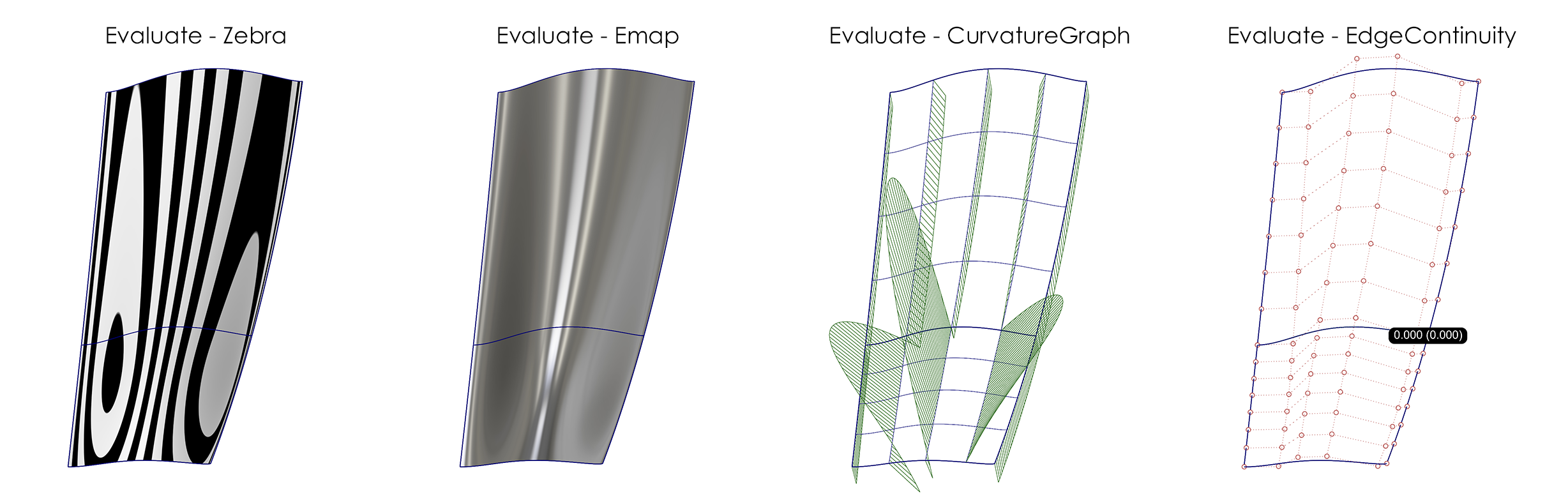
- Use
 Zebra
with Adjust Mesh… and Simple Controls set to the highest polygon mesh density. Also consider using Detailed Controls to limit the Maximum edge length of polygons and Maximum angle for an even finer display. When examining the G1 or G2 continuity between surfaces, change between Horizontal and Vertical and tumble the view; also use the orthogonal views.
Zebra
with Adjust Mesh… and Simple Controls set to the highest polygon mesh density. Also consider using Detailed Controls to limit the Maximum edge length of polygons and Maximum angle for an even finer display. When examining the G1 or G2 continuity between surfaces, change between Horizontal and Vertical and tumble the view; also use the orthogonal views. - Use
 Emap
to display a virtual environment reflected by your surfaces. You can also select your own spherical environment images.
Emap
to display a virtual environment reflected by your surfaces. You can also select your own spherical environment images. - To detect defects across and also inside of surfaces, use
CurvatureGraph
on one or more surfaces. Use Count to change the number of sections displayed. Select whether you want to analyse the U and/or V direction with Surface Hair.
Evaluate surfaces numerically
- Use
EdgeContinuity
to evaluate the G0, G1 or G2 continuity between surfaces numerically. G0continuity between curves is essential for building watertight (no naked edges) surface models.
- To display above-tolerance G0 gaps between the surfaces of your model (important for 3D printing and transfer to other CAD software), use
 ShowEdges
with Naked Edges.
ShowEdges
with Naked Edges.
Surfacing Do’s
- Try to build single-span surfaces whenever possible. Simplify surfaces, or build simple surfaces in the first place.
- Use command
 UseExtrusions
with Polysurface option to build normal Polysurfaces when you extrude. Default Rhino extrusions are simplified representations that make various surface modeling operations difficult later on.
UseExtrusions
with Polysurface option to build normal Polysurfaces when you extrude. Default Rhino extrusions are simplified representations that make various surface modeling operations difficult later on. - First build your large fillets, then build your small fillets, particularly when small fillets shall run over large fillets. For true radial G1 fillets, this script by Jim is a life-saver. Save the script and run it from an alias or keyboard shortcut.
- Use
 Sweep2
preferably only when the rail curves have the same degree and number of CPs to avoid the creation of too many spans (and thus CPs). Otherwise, try
Sweep2
preferably only when the rail curves have the same degree and number of CPs to avoid the creation of too many spans (and thus CPs). Otherwise, try
 RemoveMultiKnot
to remove multiple-knots, and re-match for possibly lost continuity.
RemoveMultiKnot
to remove multiple-knots, and re-match for possibly lost continuity. - Use
 EdgeSrf
for full manual control (CP structure, continuity) on all four sides.
EdgeSrf
for full manual control (CP structure, continuity) on all four sides. - Use
 BlendSrf
for controllable G1 and G2 blends between surface edges.
BlendSrf
for controllable G1 and G2 blends between surface edges. -
 Revolve
360° with the Deformable option and Point Count 8 to obtain a degree 3 surface without kinks. Then
ChangeDegree
to 5 in the revolution’s orientation with the Deformable option. Revolving less than 360° is buggy, so revolve as above and then use
Split
using the Isocurve option to generate valid surfaces with smaller angles of revolution.
Revolve
360° with the Deformable option and Point Count 8 to obtain a degree 3 surface without kinks. Then
ChangeDegree
to 5 in the revolution’s orientation with the Deformable option. Revolving less than 360° is buggy, so revolve as above and then use
Split
using the Isocurve option to generate valid surfaces with smaller angles of revolution.
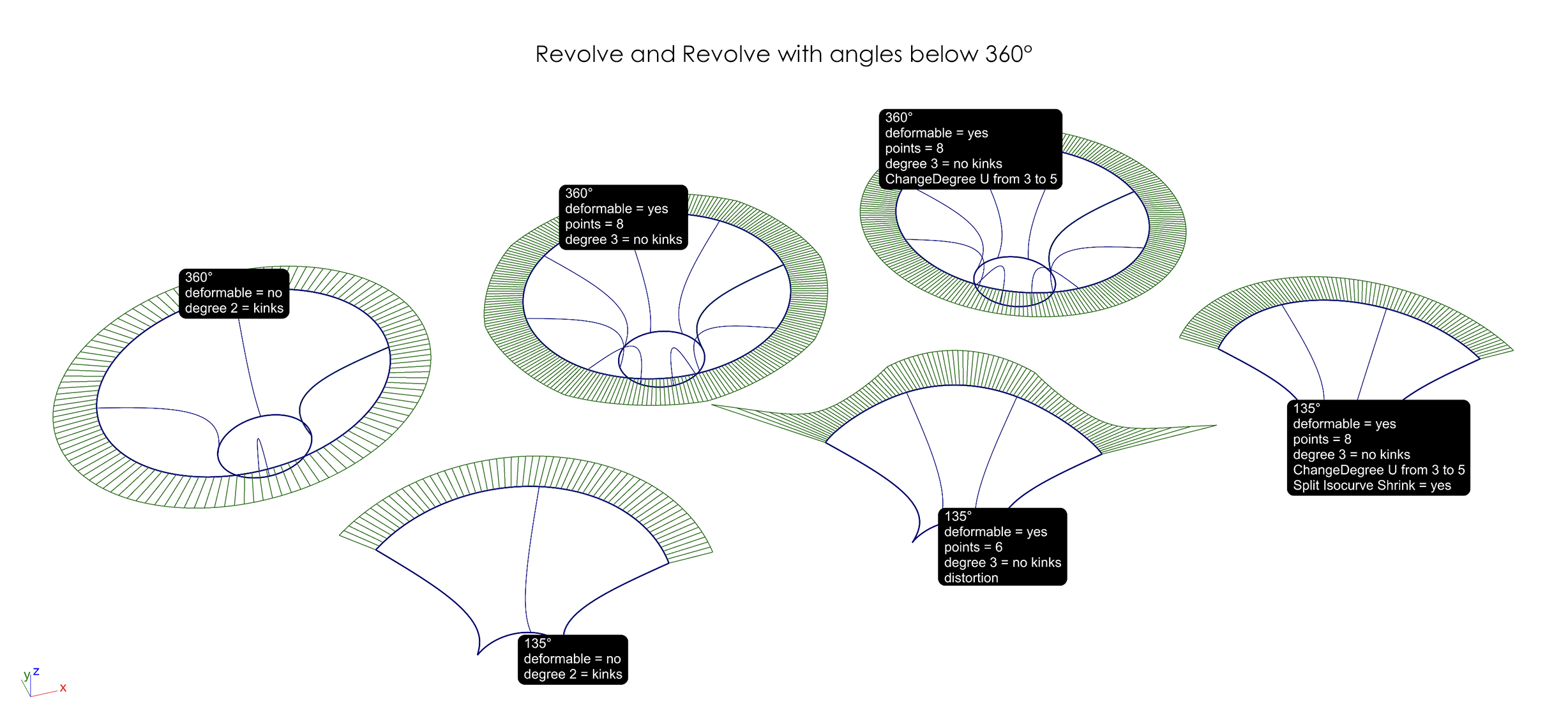
- Split revolved/periodic surfaces like cylinders, pipes, spheres, etc. in half with
Split
using the Isocurve option to eliminate the seam, or move the seam to an incongruous location with
 SrfSeam
, so it cannot interfere with trimming and matching operations.
SrfSeam
, so it cannot interfere with trimming and matching operations. - Use
 SplitEdge
on a “T” junction edge, when the surface edge you are building shall be shorter than the surface edge you are building to.
SplitEdge
on a “T” junction edge, when the surface edge you are building shall be shorter than the surface edge you are building to.
Surfacing Don’ts
- Don’t build your model using Rhino’s buggy solid modeling/boolean tools, and keep away from
 FilletEdge
, which is inaccurate and can lead to all kinds of ugly problems downstream. Always use Rhino’s proper surface modeling tools, and join your surfaces into a solid for rendering, 3D printing, or CNC-machining at the very end.
FilletEdge
, which is inaccurate and can lead to all kinds of ugly problems downstream. Always use Rhino’s proper surface modeling tools, and join your surfaces into a solid for rendering, 3D printing, or CNC-machining at the very end. - Don’t build from trimmed edges, if you can avoid it, or to adjacent edges with too many isocurves arriving at that edge.
- Don’t build surfaces with three edges. Singularities (corners with a collapsed fourth surface edge of zero length) make filleting, matching, or joining very difficult or even impossible.
- Don’t use
 Explode
after using
Explode
after using
 Join
to test for naked edges while modeling. It permanently changes trimmed edges. Always use Undo instead.
Join
to test for naked edges while modeling. It permanently changes trimmed edges. Always use Undo instead. - Don’t use
 Rebuild
, because it will almost always destroy your surface’s CP structure, and your surface might deviate substantially from adjacent surfaces.
Rebuild
, because it will almost always destroy your surface’s CP structure, and your surface might deviate substantially from adjacent surfaces. - Don’t use
 NetworkSrf
(“notwork”) and
NetworkSrf
(“notwork”) and
 Patch
(“botch”), as they create nothing but problems with continuity, filleting, and particularly UVN CP manipulation.
Patch
(“botch”), as they create nothing but problems with continuity, filleting, and particularly UVN CP manipulation.
MISCELLANEOUS
Curve and surface anatomy
To understand the fundamentals of NURBS curves and surfaces, see this Autodesk Alias page.
To understand the fundamentals of surface continuity, see this Autodesk Alias page.
To understand the fundamentals of curvature, see this Autodesk Alias page.
To display the knots/spans/isocurves - (ab)use InsertKnot, which temporarily displays them (click Cancel right after). Please note: Rhino’s EditPtOn shows you the “Greville points”, not the knots (in Alias, the knots are called “edit points”). Consider setting the Isocurve Density to 0 in Settings… (Options in Windows) > General, so only “real” isocurves are shown (unless you need extra isocurves for snapping, or other modeling tasks). Alternatively, use CurvatureGraph and set Density to 0; a hair will be shown at each knot.
