This is an introductory tutorial for designers who want to learn how to set Clipping Sections and extract dynamic drawings of sections and elevations. We will cover the
![]() ClippingSections
,
ClippingSections
,
![]() ClippingDrawings
,
ClippingDrawings
,
![]() UpdateClippingDrawings
,
UpdateClippingDrawings
,
![]() EditClippingDrawings
,
EditClippingDrawings
,
![]() ClippingPlane
, and
ClippingPlane
, and
![]() Dim
commands and many of their options. You can add & remove objects, change settings, and update your sections and elevations when necessary, including laying them out with a Detail & Layout ready for printing.
Dim
commands and many of their options. You can add & remove objects, change settings, and update your sections and elevations when necessary, including laying them out with a Detail & Layout ready for printing.
Before We Start
Let’s make sure we have set Rhino’s User Interface to a similar setup:
- Go to the Window menu
- Click on the submenu Window Layout
- Select Default Window Layout
This will configure the toolbars and panels to the same setup and location as the one used in this tutorial.
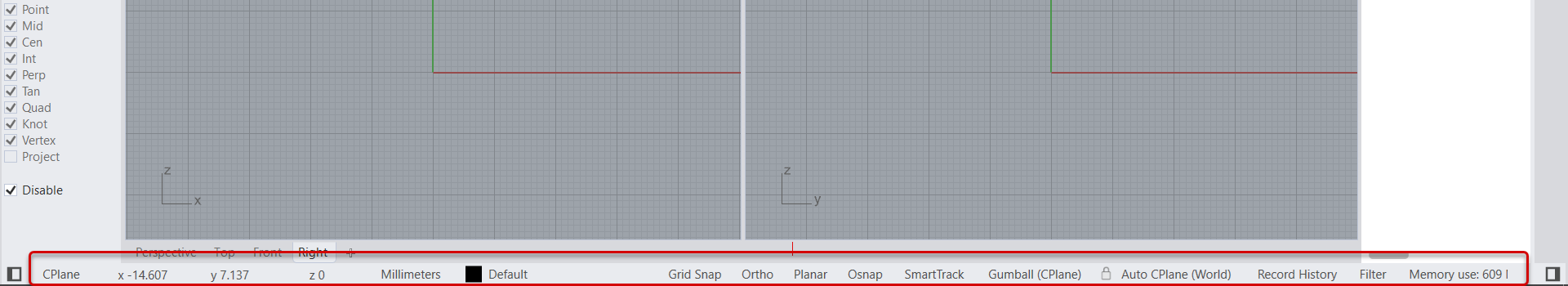
Now go down by the Status Bar and make sure everything is disabled except for OSnap and Gumball, which should be enabled. On the left, by the Osnap Control , make sure all OSnaps are unchecked and then check End. This is just to make our lives easier as we model.
As for the
![]() Gumball
make sure it is set to Snappy Dragging so it references all
OSnaps
we mentioned in the tutorial. You can set this in the Command Line options for the
Gumball
make sure it is set to Snappy Dragging so it references all
OSnaps
we mentioned in the tutorial. You can set this in the Command Line options for the
![]() GumballSettings
command.
GumballSettings
command.
Download and
![]() Open
the CS-Townhome-Start.3dm model.
Open
the CS-Townhome-Start.3dm model.
Make a Clipping Section
In this tutorial, we will show how to extract dynamic vector drawings of sections and elevations in your Rhino3D model. Most of the commands we will use are located under drafting menu and sections submenu.
Let’s create two vertical sections. Run the
![]() ClippingSections
command from the drafting menu and sections submenu, then click on create. The command will prompt you to select the objects to section through, or you can press Enter to section through all visible objects.
ClippingSections
command from the drafting menu and sections submenu, then click on create. The command will prompt you to select the objects to section through, or you can press Enter to section through all visible objects.
Let’s press to section through all objects.
Clipping Section Options
Next, you will see a number of options, such as direction, which could be set to XY or a custom direction. Those directions are relative to your active seaplane.
- You can set a custom depth to view a slice of your model.
- You can choose to clip the viewports.
- You can set the name prefix and also set the name label to text dot or no label.
- You can choose to save the section view to the named views for easy reference in layout and modeling.
- The flip option simply flips the direction of your section.
Once you are set with all the options, you can now place them in your scene.
Include or Exclude Specific Object & Layers
At the time we created the sections, we set them to cut through all visible objects in the scene. You can change that to include or exclude specific objects and layers. Let’s set the section to cut through all active modeling layers except clipping planes and default layers.
Clip or Unclip Specific Views
You can clip your model view and perspective or other views.
You can also unclip them. Let’s update Section A01 to include the same set of layers.
Make Clipping Drawings
Now that the sections options are set, we can extract dynamic drawings using the
![]() ClippingDrawings
command. You can type the command directly or you can access it from the drafting menu under Sections and then click on Create Drawings. The command prompts you to select your clipping sections. Let’s select both sections.
ClippingDrawings
command. You can type the command directly or you can access it from the drafting menu under Sections and then click on Create Drawings. The command prompts you to select your clipping sections. Let’s select both sections.
Clipping Drawings Options
A set of options appear for you to configure.
- The first is the placement point that you can enter manually or place interactively by picking a point in your XY plane. You might want to pick a location away from your 3D model. so that it is easy to zoom in and isolate when you are illustrating it in your viewport or in a layout detail.
- Drawing output of your sections can be set to include section hatches and solid caps.
- You can also draw the objects in the background. If you select the Add Background option, the model might update more slowly depending on how big it is.
- Under the background, you can also select the projection to be either parallel or perspective.
- You can add hidden lines and scene silhouette.
Drawing Layer Visibility
The drawings output is organized in layers and you can access in the layer manager. All the drawing layers are locked by default. Let’s look at the details of section A00 in the layer manager.
There are two groups of layers, the drawings and the background. You can control the visibility of your section parts by changing the visibility of the layers they are in.
Updating Clipping Drawings
The drawings update automatically when you transform the clipping a plane. However, when you add or remove objects, you will need to run the
![]() UpdateClippingDrawings
command to see the update. This is by design to help make multiple edits to your model and update the drawings all at once.
UpdateClippingDrawings
command to see the update. This is by design to help make multiple edits to your model and update the drawings all at once.
Let’s rotate the clipping plane of a section to see how the associated drawings update.
Editing Clipping Drawings
Suppose you want to change the projection of your drawing from parallel to perspective or change any of the other drawing options. To do that, you need to run the
![]() EditClippingDrawings
command.
EditClippingDrawings
command.
In the options, change the projection from Parallel to Perspective and the model updates while the command is still running.
Creating Elevations (and Floor Plans)
Now, in order to create an elevation, place the clipping plane outside the model and make sure that the Add Background option is active.
For example, you can turn one of the sections into an elevation by dragging the clipping plane outside the model.
The drawing updates, and if you check the drawings layer, it only includes the base slab now.
Elevation curves are now included in the background layer.
Creating Drawing Dimensions
The output of the
![]() ClippingDrawings
command updates dynamically, and it produces vector geometry that you can snap to and add dimensions from the Drafting pulldown menu (v8 only), including the
ClippingDrawings
command updates dynamically, and it produces vector geometry that you can snap to and add dimensions from the Drafting pulldown menu (v8 only), including the
![]() Dim
command.
Dim
command.
Feel free to download the completed CS-Townhome-Final.3dm model.
Learn More
Visit our Clipping & Sectioning links to learn more about Clipped Views & Dynamic Vector Drawings tools in Rhino 8.
Intro to a Visual Workflow
Learn how to clip parts of your model and set a clipping depth for visualization and presentation purposes.
Intro to Section Styles
Learn how to attach hatch and edge styles to objects, layers, and clipping planes directly.
