Overview

 |
Workflows overview... |
Workflows in architecture are typically unique for each building, and are highly dependent on the people and requirements involved. Each workflow contains specific tasks. The following sections introduce a series of tutorials that are task-based. They are grouped into four sections: modeling setup, conceptual design, detailed design and prototyping.
2.1 Modeling setup
There are a five steps to follow in each new project to ensure proper organization and settings of the modeling environment:
- Create project folder and give it a descriptive name. As the project grows, you may add new files and subfolders. Make sure that all your files are named to show in the desired order, and their names describe the content for quick reference.
- Create a new project template with appropriate document properties, options, layers and reference geometry.
- Create your model as close to the World origin as possible.
- Generate scaffolding or reference geometry, guides, and construction planes to match the model orientation.
- Set up views and snapshots for effective visualization.
2.1.1 Project template
 |
Template files in Rhino... |
A template is a Rhino file that stores all document settings and is used when you start a new file. Templates include all the information that is stored in that template file including objects, blocks, layouts, layers, viewports layout, notes, grid settings, units, tolerances, render settings, dimension settings, and any other setting related to the document. You can use the default templates that are installed with Rhino, which come with viewport layouts, units and default document settings. You can create custom templates using different document settings for render mesh, tolerances, color scheme, layers, lights, or even include geometry and notes.
The New command begins a new model. It uses the default template unless you change it to one of the other templates. To change the template that opens by default when Rhino starts up, choose New and select the template file you would like to open when Rhino starts, then check the Use this file when Rhino starts box.

Create the template:
- Start a new model.
- Select a Rhino template such as Large Objects - Meters.3dm.
- From the Render menu, click Current Renderer, and then click Rhino Render.
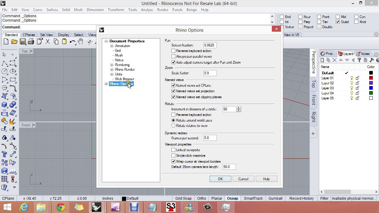
Setup the Document Properties:
- From the File menu, click Properties.
- In the Document Properties dialog, on the Grid page, change the Grid line count to 100, Snap spacing to 0.05, the Minor grid lines every 0.1, and the Major lines to every 10.
- On the Mesh page change the setting to Smooth and slower.
- On the Rhino Render page, check Use lights on layers that are off.
- On the Units menu, Model units, set Absolute tolerance to 0.001 and Angle tolerance to 0.5. Under Layout, set Layout units to Millimeter, and Absolute tolerance to 0.1, Angle tolerance to 0.5.
- For Location, change to Los Angeles, CA USA.
- For Linetypes set Linetype scale to 100 mm.
- Click OK.
Setup Layers and Properties panels:
- Open the Layers panel and rename Default to Reference and delete other layers.
- Open Properties panel and set the Camera Lens Length to 50 (35-50 is appropriate to architectural modeling).
- Open Named CPlanes and Help panels and turn off all other panels if any is open.
Save the template:
- From the File menu, click Save As Template and name House_Decimal_Meters_0.001.3dm. This file with all of its settings is now available any time you start a new model.
Set the template as default:
- From the File menu, click New.
- Select the template you want to use as the default template.
- In the template dialog, check the Use this file when Rhino starts.
2.1.2 Productivity
Depending on the project type and your workflow, it might be a good idea to set up quick access to your commonly used commands and options to improve workflow productivity. For example if you need to draw a lot of vertical lines, then it helps to write a macro to run the line command with the vertical option (!_Line Vertical) and add it as a keyboard shortcut or as a new command to the context menu or popup toolbar. For details about macros, check the wiki article Creating Macros and the Rhino help.

 |
Commonly used macro notation... |
First make a list of commands and options to use and you can always change the list based on your workflow. For example, we might decide to create aliases for the following:
- Switch to plan view (Pl) !_Plan
- Switch to World perspective view (Per) !_SetView _World _Perspective
- Hide selected (H) !_Hide
- Isolate selected (I) !_Isolate
- Set CPlane using 3 points (C3) !_CPlane _3Point
- Create vertial line (VL) !_Line _Vertical
- Create vertical plane (PV) !_Plane _Vertical
- Turn the Grid on (GOn) !_Grid _ShowGrid=Yes _ApplyTo=AllViewports _Enter
- Turn the Grid off (GOff) !_Grid _ShowGrid=No _ApplyTo=AllViewports _Enter
Here is how it looks when you add the above as Aliases (note that ZS comes by default with Rhino)

Add a new custom toolbar button for the grid on/off to the popup toolbar.

2.1.3 Appearance
You can customize the color scheme of the workspace and geometry. To do that go to Command Options > Appearance > Colors. You can always restore defaults to revert to original settings. You can also customize display modes to help productivity and presentation. One important setting when working with NURBS surfaces is to indicate the U and V iso directions of surfaces and their up direction by assigning distinct colors. You can also specify edge thicknesses and point sizes in each display mode.

2.1.4 Plugins
You may need to use plugins to access specialized features and workflows. Installed plugins are saved in a special folder and Rhino knows where to find them. Rhino ships with many plugins, especially those for file input/output. If you run the PluginManager command, you can see the list of plugins.

Most third party plugins are available through the package manager in Rhino 7, or have their own installer. Rhino places installed plugins in the proper folder and loads when Rhino opens next time. Rhino also recognizes if there is a toolbar that comes with the plugin and allows loading it by the user. If there are plugins that you do not like Rhino to load, you can place load protection by un-checking the Enabled checkbox for these plugins. Next time you open Rhino, they will not load. You can always check the box again to permit loading.
There are two plugins that we will use that do not come with the Rhino installation for Windows. Those are PanelingTools and SectionTools. In order to install them, run the PackageManager command, search for each and click Install. Restart Rhino and both plugins will load and you can see their menu at the top.

2.2 Concept modeling
Concept generation is reflective and has a lot of uncertainty about the final product. Designs go through multiple iterations before reaching the final solution. Most designers start their concepts with sketching on paper, then bring the sketches to the 3D modeling environment, model and adjust till researching a solution. It is a good practice to keep an organized record of the 3D modeling steps to be able to communicate and modify easily. A common workflow for concept design is to start with the site geometry, import sketches, generate the mass model, analyze, edit, and share. We will cover all of these aspects using step by step tutorials.
2.2.1 Site modeling
This step involves importing the terian geometry and setting up the site and building footprint geometry in model space.
2.2.1.1 Site terrian
Geographical information and land use is nowadays available in digital format with multiple layers of topographical and other information which helps bring site data directly to the modeling environment. There are many plugins for Rhino and Grasshopper to import site terrain and surroundings. The Food4Rhino website is a place where most of the Apps for Rhino and Grasshopper are published and you can find relevant plugins using keywords such as topography, <b.GIS and site. Another way to get terrains is to import the contours form a land survey and create the terrain surface inside Rhino using the contours as reference geometry. The following two tutorials show detailed workflow of how to import the project site data using two Grasshopper plugins:
| Elk Site Tutorial handout... |
| Meerkat Site Tutorial handout... |
The project terrain data would look like the following in wireframe and rendered modes:

Once you import the GIS data for your location with topography, roads and buildings information when possible, there are a couple steps needed to place the geometry and cut out a smaller part for your site.
2.2.1.2 Terrian geometry
Place the imported terrain so that the center of the site is near the Rhino World origin (0,0,0). This is important to be able to model with accuracy and perform operations such as Booleans and intersections correctly within the model tolerances.

2.2.1.3 Site terrain
- Use the Box command that intersects with the terrain (make the box taller than the terrain to ensure that the Booleans operation can be calculated accurately).
- Use BooleanSplit extruded box by the terrain.
- Define site boundary around the world xy-plane origin. For this tutorial, draw a 40*40 meter rectangle and rotate 30 degrees clockwise.

You can take part of the terrain closer to the site to model the concept. The following workflow shows how to take part of the terrain and define site boundaries and flatten part of the site.
2.2.1.4 Site boundary
- Project the flat outline to the terrain.
- Copy the flat outline to the bottom and lowest and highest points.

2.2.1.5 Site geometry
- Extrude base curve using the Gumball widget and Cap (or use Solid option in - ExtrudeCrv command)
- BooleanSplit the extruded box by the terrain.
- then BooleanSplit the terrain by the extruded box.
- Delete unwanted split parts

2.2.1.6 Setup the site construction planes
Set CPlane to be at the center of the site and save three main CPlanes for quick reference.
- CPlane (use the 3Point option) to set the CPlane to the Top, Front and Side relative to the site orientation
- In the Named CPlane panel, save the new construction planes and name Top, Front and Side

2.2.1.7 Setup the building footprint
Create the building base and flatten the site in the location where the building mass is located (building dimensions are 2466)
- Create the building base. Use the Rectangle command with Center option, and set dimensions to 24 and 6
- Create a Box using the rectangle as reference and extend the side of the box facing the slope across the site so it intersects completely.
- Use BooleanSplit to cut the site
- Calculate the volume of the cut out part to estimate the cost. Use the Volume command (~420 cubic meters)

2.2.2 Mass modeling
Generating building geometry involves creating scaffolding, placing sketches, and modeling the building’s main geometry elements.
Scaffolding is very useful to define reference geometry to help create the building. This geometry helps define things such as orientation, dimensions, and levels. Scaffolding geometry can be used as a reference when creating the building geometry.
2.2.2.1 Scaffolding
Scaffolding and sketches are used as a reference to create the building surfaces. We will create scaffolding for mass, levels and stairs. Also create model space construction planes and save to use for modeling.
- Make the Top CPlane active (double click Top CPlane in the list of Named CPlanes panel)
- Create a new layer and name Scaffolding with sublayers named Mass and Sketches. Make the Mass layer current
- Use Rectangle with Center option sized (24*6) located at the origin of the Top CPlane
- Draw two center Lines of the rectangle in both directions
- Draw a vertical Line from center with 8m length
- Divide the vertical line into 8 segments to create reference points that are spaced by 1m
- Copy the base rectangle and center lines vertically to level 3 and 6 m
- Create a line at the base that is 3m long
- Create two Circles (radius=1) on lower and middle levels to mark the staircase

Place the top sketch
- Use the Picture to place top sketch
- Use Plan command to align parallel to active CPlane
- Use Gumball to locate and scale the picture to fit the mass dimensions
- Change transparency to 30%:
- Select the picture
- Go to Properties Panel > Materials > Picture > transparency and set to 30%
- Use Lock command to lock the sketch in place

Place the elevation sketch
- Create new CPlane that aligns with the model front view through the model origin and save in the Named CPlanes and call Front
- Place the elevation Picture and Move/Scale to fit dimensions
- Change transparency to 30% (same steps for top)

Place the section sketch
- Create a new Side CPlane and save it in the Named CPlanes
- Place the section using Picture command then Move, ROtate or Scale to fit the correct dimensions
- Change transparency to 30% (same steps for top)

Go back to the perspective view to verify that all of the sketches are oriented and located correctly and to scale

2.2.2.2 Massing
Massing involves creating base geometry for the mass model with minimum details.
Create initial massing geometry
- Switch to Top CPlane (saved earlier in Named CPlanes panel)
- Create a new Building layer and a Floors sublayer, and make it the current layer
- Use Box command to create first and second floor slabs (thickness = ~0.2 m)
- ExtrudeCrv the base curve and put in a new Walls layer
- Use the Cylinder command to place staircase mass, put in Stairs layer

Add openings.
- Switch to the Front Cplane (saved in the Named CPlanes earlier)
- Create openings and place in a new Windows layer: draw a rectangle on the side face where the openings are to be created, use the Split command, then select the split portion of the face and change the layer to Windows.
- Calculate the area of walls and windows using the Area command (e.g. windows area = ~140 sqm, walls = ~220 sq m)

Add front and side platforms/balconies
- Draw curves, ExtrudeCrv, then Join and MergeAllFaces
- Use ortho angle = 30 to define stairs’ slope (30-37 degrees is the recommended stairs slope)

Generate fill
- ExtrudeSrf platform surface in the -Z direction, then BooleanSplit with the site to generate the fill solid
- Calculate the overall volume using the Volume command = ~54 cubic meter for the fill

Clean up
- Finally, Trim rails and platform surfaces

2.2.2.3 The roof

 |
Download rooftest.3dm |
The design uses a free form for the roof. Use reference sketches to create main curves of the roof in each picture plane, then edit the curves to place correctly in 3D space. Use the curves to generate the roof surface.
Roof outline curves
First, trace the roof outline in the top picture. Snap to other curves and the scaffolding geometry when relevant.
- Move the Top CPlane to align with the top picture
- Use the Curve command to trace one side and adjust control points to match the sketch. Try to create the curve with as few control points as possible
- Use ProjectToCPlane to ensure curves on plane (snapping can cause control points to go off the plane)
- Use the Mirror command to reflect the curves and ensure symmetry
- Repeat the tracing process for the section sketch

Adjust top curves to match elevation contour
- Only adjust the curves on one side, then mirror them
- Set the CPlane to the Front named CPLane.
- Set the selection filter to ControPoints only.
- Move the points vertically using the Gumball widget
- Adjust using the Side named view as well
- Mirror the final curves
Test curves’ smoothness using the CurvatureGraph command. The points mark significant locations on the curve where curvature changes from concave convex, or the middle of a long span.

Roof as a Patch surface
Having boundary curves and cross section curves might be enough to create a good patch surface.
- Use Patch command and select roof 3D curves. Use the Preview option to see how the patch surface looks and adjust settings
- Use Pull command to pull the outline curves to the patch surface to be able to trim the surface with.
- Use Trim command to trim surface with pulled curves
Notice that the surface parameterization (direction of isocurves) may not be in a desired direction. Also the surface is not symmetrical.
Repeat the Patch command with a starting surface.
Create a tilted Plane through the three corner points and make the plane slightly bigger. Use that plane as a starting surface in Patch command the repeat steps above to create the patch surface.
Notice that parameterization followed the plane direction. Also when comparing the mean curvature of the two patches, the second comes out smoother (notice the transition from blue to red).
Notice that both surfaces are trimmed surfaces.

Roof as a Loft surface
Loft surfaces are typically easy to set up, construction curves are in one direction and are easy to adjust and match. History also allows more interactive editing until reaching a desirable solution.
- Divide the front curve into 5 segments.
- TweenCurves between middle and end, then adjust curve ends to align with the points. Use PointsOn command to move control points. Alternatively, and if you have a temporary surface from patch use Project to locate and trim tween curves on the surface.
- Mirror the curves created with tween curves.
- Use Loft command using all the curves with History option to be able to adjust the surface as needed. Turn on history recording for a specific command by clicking on the Record History in the Status Bar before running the command.

- Test mean curvature using CurvatureAnalysis

Roof as a SubD surface
- Create SubDPlane from center and set X=4, Y=3
- Use Reflect before editing to apply symmetry.
- Use Crease and select the end vertix to get a sharp corner
- Sub-object select curves and vertices of the subD surface (select with Shift+Ctrl down), then move to create the roof form using the 3D curves as a guide. You only need to work on one side.
- You can convert the subD surface into NURBS surface using the ToNURBS command.

Tip: Use Tab key to toggle between Box and Smooth modes of the SubD preview. It is easier to pick vertices in Box mode, but you can only see the final smooth surface in Smooth mode.

The concept geometry putting the mass and roof together:

2.2.3 Concept visualization
Visualization is an essential part of concept development and communication. Rhino has a rich set of tools for quick visualization, but also to produce high resolution renderings. Viewport display modes offer quick access to a variety of display modes. They all are working modes where you can continue to edit and navigate your model. There are also tools to assign materials, create renderings and capture images that we will explore in the next tutorial.
2.2.3.1 Display modes
A variety of built in display modes are included with Rhino and these are accessible in the Display panel which can be found in the Panels drop down menu if not already shown. Many commonly changed settings can be altered within this panel. Click the button at the bottom of the display panel to open the full options.
Display mode settings are system specific and are not part of the 3dm file. To export and import customized display modes, use the Options command and navigate to View>Display Modes. Any existing display mode can be copied as the starting template for a new user-defined display mode.

Some similarities can be found between certain default display modes and these are good to understand as you experiment with customization. For example, the Artistic and Pen modes are all derivatives of the Technical display mode. These modes require an initial calculation time dependent upon the complexity of the scene. Hidden lines and silhouettes can be visualized in these modes making them unique.


The Rendered mode uses many of the settings found in the Rendering panel which can be shown via the Panels drop down menu if needed. Namely, the display of assigned materials and cast shadows distinguish this mode from a standard Shaded display.

The Arctic mode overrides any material assignments and custom lighting to produce a soft shadowed grayscale display mode. Materials remain in the file and are still assigned. By default, transparent materials such as glass will remain transparent in the Arctic mode. This option is configurable within the display mode settings.

The Raytraced mode is unique among the display modes in Rhino. This mode actually renders the model interactively in the viewport. Reflections between objects as well as indirect illumination (the bouncing of light) are calculated.

Render mesh modifiers can be used to change the look of the model without impacting the actual geometry. One example is the thickness modifier for surfaces which when enabled will make any surfaces appear as solid (with thickness) in shaded modes. It is accessed when selecting surfaces, then in the Properties panel, select the Thickness button.

2.2.3.2 Named views
You can save your views in the Named Views panel. Once saved, you can restore at any point during modeling. Double click the thumbnail image of the saved view in the Named Views panel to restore it in the active viewport.
Use the icons at the top of the panel to access various named views functionality. Among these controls you can import named views from another 3dm, edit a named view by simply rotating the viewport as well as animate the transition between views.

2.2.3.3 Clipping the view
Another feature that can be quite helpful in concept visualization is the use of clipping planes. You can create new clipping planes with the Clipping Planes command and enable at the active viewport using EnableClippingPlane command.

Multiple clipping planes can be made active at any viewport. Select the clipping plane object, and in the Properties panel you can see which viewports are affected. Other clipping plane options such as showing thickness for edges or adding a solid fill can be set inside each display mode.

2.2.3.3 Saving viewports
To save a high resolution image of the viewport, you can use the commands ViewCaptureToFile or ViewCaptureToClipboard.
The view capture allows setting custom resolution for printing or other presentation purposes. Note that scaled Raytraced view captures will require a re-render of the viewport to account for the new size. Other modes will scale up during capture relatively fast.

2.2.4 Concept analysis
Analysis helps evaluate the design option and develop the concept. We have done some analysis above for the roof surface continuity, the overall volume of cut and fill in the site and building orientation. Rhino supports many workflows for concept analysis and the following includes some of those.
Shadows study Use SetOneDaySunAnimation, then PlayAnimation to view and RecordAnimation to save.

Basic scheduling: Make sure you create separate surfaces and solids for the walls, floors, glass, outdoor pavements, fills, etc. and organize in separate layers to be able to assign colors, linetypes and materials for rendering. You can also attach data to objects to calculate things like overall area or volume.

Basic line drawings Use Section on the Top view to create sections Use Make2D of the current view. Note that Make2D recognizes clipping planes and you can extract section perspective using clipping planes active in a perspective view. You can also utilize specialized plugins such as SectionTools by McNeel, that help create dynamic sections and 2D layouts that update with model changes.

2.3 Detailed modeling
2.3.1 Advanced NURBS modeling
As the model progresses from concept to details, changes become more time consuming. Direct modeling favors a more linear approach where the overall concept is decided upon before starting to add more details. In Rhino, there are few parametric features, such as blocks and history, that allow for updates past the concept stage but they are typically more limited. Algorithmic modeling is more suitable for a nonlinear approach to design where details can be worked on before the concept is finalized. That is because it is easy to adjust at a later stage. Workflows past concept stages include advanced geometry, rationalization, visualization and documentation.
2.3.1.1 Building details: spiral staircase
Building details include circulation, layout, materials, structure and floor plans. This work involves accurate modeling and considerations of building standards and material specification. The following are the steps to create the spiral staircase.
Create the stairs’ scaffolding
- Locate the staircase center to be on top of the lower floor.
- Adjust the named CPlanes origins to be that center point.
- Make circles with radiuses equal 0.15, 0.95 and 1m. Each step width equals 0.8m.
- Floor to floor height equal 3m.
- Use Distance and Dim commands to measure and mark dimensions. Note that you need to change the CPlane to be parallel to vertical center line before you can apply the dimensions.

Create one step curves
- Use the stairs centerpoint
- Draw inner Arc. Angle = 360/number of steps per full rotation. For 12 steps, angle = 30 degrees.
- Draw outer arc. Need to decide step width
- Draw lines connecting endpoints of the step, then join all curves (use Line and commands).
- Draw inner and outer circles of the step end
- Delete inner curve, Trim then Join step curves join into 2 curves.

Create one step solid
- Use PlanarSrf to create the step surface.
- ExtrudeSrf with “0.08” for the thickness.
- Calculate step tp step distance: floor to floor height is 3m and number of steps is 12 steps, so the distance from one step to the next is 0.25m.
- Move down by 0.25m.

Create all steps
- Change CPlane so that Z direction points downwards.
- ArrayPolar command with 11 steps StepAngle=30, offset option “ZOffset=0.25” to create all the steps.

Add staircase pole and upper floor slab
- Use the Cylinder command to create the pole.
- Use the PlanarSrf and ExtrudeSrf (thickness=0.1) commands to create the slab.

If you find yourself copying the same geometry, such as the step solid in the staircase tutorial, then it is best to model that geometry using blocks. This helps keep model size smaller and allows designers to change the geometry without remodeling. The following tutorial creates steps and railing as blocks.
2.3.1.1 Building details: blocks
Create a block
- Copy one of the steps into new layer
- Select the step geometry, then run Block to define a new block. The selected step will turn into a block instant.
- Run What command to confirm that it is a block instant.

Edit the block
- Create additional geometry to add to the step block and put in new layer.
- Run BlockEdit to edit, remove and add the new geometry to the block

Recreate the Steps (run ArrayPolar)

Create additional blocks
Create new block to cover the rest of the pole.
- Create new Layer for the pole block.
- Copy step added geometry InPlace.
- Move to be on top of the top step.
- Extrude top cap by 0.08m.
- Run Block to create a new block.
- Array (or Copy) the pole block vertically to cover the whole pole.

Spindles’ block
- Change CPlane to Front, then bring origin to the spindle center (CPlane, and set origin point).
- Change to Plan view
- Create profile curve
- Use RevolveCrv to create the surface
- Cap to create the solid
- Block the solid with reference point for the handrail
- Change CPlane to Top, locate one spindle on the first step, then run ArrayPolar with the same options as the steps.

The handrail
- Use InterpCrv to connect the tops of the spindles.
- Pipe through the curve for circle cross section (r=0.02), or Sweep for custom cross section.
- Cap the ends of the pipe

