There are an infinite number of complex and tricky surfacing problems. In this chapter, we will look at several tricks that help in getting certain types of surfaces built cleanly. The goal, apart from showing you a few specific techniques used in these examples, is to suggest ways in which the Rhino tools can be combined creatively to help solve surfacing problems.
In this chapter, you will learn to make soft domed button shapes, creased surfaces, and how to use curve-fairing techniques.
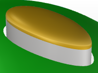
Dome-shaped buttons
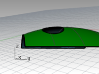
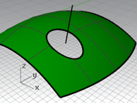
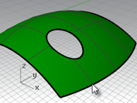
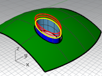
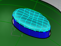
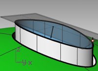
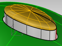
The surfacing goal in this exercise is to create a dome on a shape like a cell phone button where the top must conform to the general contour of the surrounding surface but maintain its own shape as well. There are a number of ways to approach this; we will look at three methods.
Exercise 7-1 Soft domed buttons

Open and prepare the model
- Open the model Button Domes.3dm.
The key to this exercise is defining a custom construction plane that represents the closest plane through the area of the surface that you want to match. Once you get the construction plane established, there is a variety of approaches available for building the surface.
There are several ways to define a construction plane. In this exercise, we will discuss four methods: construction plane through three points, construction plane perpendicular to a curve, construction plane tangent to a surface, and fitting a plane to an object. - Use OneLayerOn to turn on the Surfaces to Match layer to see the surface that determines the cut of the button.
Create a custom construction plane using three points method
- Turn off modeling aids ortho and grid snap.
- Start the CPlane command with the 3Point option (View menu: Set CPlane > 3 Points).
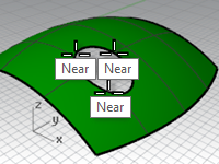
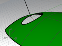
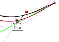
- In the Perspective viewport, using the Near object snap, pick three points on the edge of the trimmed hole.
The construction plane now goes through the three points. Notice the construction plane origin is at the first point.
- Rotate the Perspective viewport to see the grid aligned with the trimmed hole.
Create a custom construction plane perpendicular to a curve
With a line normal to a surface and a construction plane perpendicular to that normal line, you can define a tangent construction plane at any given point on the surface
- Start the CPlane command with the Previous option (Viewport title right-click menu: Set CPlane > Undo CPlane Change).
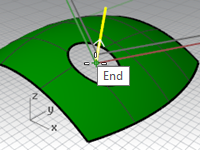
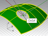
- Use the Line command with the Normal option (Curve menu: Line > Normal to Surface) to draw a line normal to the underlying surface at a point near the center of the trimmed hole.
Set the command-line option for IgnoreTrims=Yes so that the line can be drawn from a point inside the trimmed hole in the surface. - Start the CPlane command with the Curve option (View menu: Set CPlane > Perpendicular to Curve).
- Pick the normal line.
- Use the End object snap and pick the end of the normal line where it intersects the surface.
The construction plane is set perpendicular to the normal line.
Create a custom construction plane to a surface
This function sets the construction plane to match a surface. The placement is constrained so that the construction plane is tangent to the surface at any given point on the surface. This works like the previous method without the need to make the normal line.
- Set the CPlane to the previous option (Viewport title right-click menu: Set CPlane > Undo CPlane Change).
- Delete the normal line.
- Start the CPlane command with the Surface option (View menu: Set CPlane > Origin).
- Select the surface.
- For the CPlane origin, change the IgnoreTrims option to Yes, then pick a point near the center of the hole.
- For the X axis direction, pick a point in the direction of the long dimension of the trim curve.
The construction plane is set tangent to the surface at the origin.
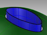
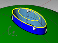
Option 1 - Use a loft surface to make the button
Using the PlaneThroughPt command to create a surface through a sample of extracted point objects will generate a plane that best fits the points. The CPlane command with the Object option places a construction plane with its origin on the center of the plane. This is a good choice in the case of the button in this file. There are several curves from which the points can be extracted—the edge of the button itself, or from the trimmed hole in the surrounding surface.
-
Start the CPlane command with the Previous option (Viewport title right-click menu: Set CPlane > Undo CPlane Change).
-
Turn on the Surfaces and the Curves layer. Make the Curves layer the current layer.
-
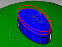
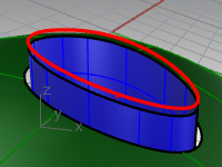
Start the DupEdge command (Curve menu > Curve from objects > Duplicate edge) to duplicate the top edge of the button surface, press Enter.
-
Copy the duplicated curve vertically twice, about .5mm apart.
The vertical position of these curves will determine the shape of the button.
-
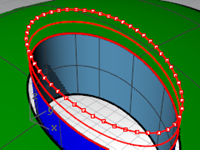
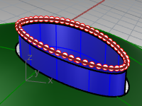
Use the Divide command (Curve menu: Point Object > Divide curve by > Number of segments) to mark off the top copied curve with 50 points.
Set the command-line options to Split=No and GroupOutput=Yes.
-
Use SelLast to select the points just created.
-
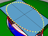
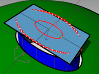
Use the PlaneThroughPt command (Surface menu: Plane > Through Points) with the selected points.
-
Press the Delete key to delete the point objects that are still selected.
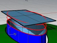
A rectangular plane is fit through the selected points.
-
Use the CPlane command with the Object option (View menu: Set CPlane > To Object) to align the construction plane with the plane.
-
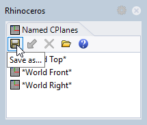
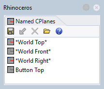
On the View menu, select Set CPlane, click Named CPlanes, then click the SaveAs icon to save and name the custom construction plane Button Top.
This will allow you to restore this custom construction plane at any time. -
Delete the surface you used to create the Button Top construction plane.
Loft the button
-
Set the Surfaces layer as the current layer.
-
Use Loft to make the button.
-
Select the top edge of the surface and the two copied curves.
-
After selecting the curves, on the command-line, click the Point option.
-
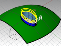
For the Loft endpoint, make sure the view that has the custom construction plane is the current view, then type 0 (zero) and press Enter.
The loft will end at a point in the middle of the plane, which is the origin of the construction plane.
-
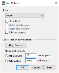
In the Loft Options dialog box, under Style, choose Loose, click OK.
With the Loose option, the control points of the input curves become the control points of the resulting surface, as opposed to the Normal option, in which the lofted surface is interpolated through the curves.
-
Turn on control points on the lofted surface.
-
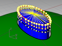
To select the next ring of points out from the center, select one point, and then use SelV or SelU to select the whole ring of points.
-
Use the SetPt command (Transform menu: Set XYZ Coordinates) to set the selected control points to the same CPlane Z elevation as the singularity in the center of the surface by snapping to the point at the singularity.
You have a custom CPlane active and you can set all the Z values of the points, relative to the CPlane. The Z values will be the same as the middle point.
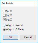
Un-check the Set X and Set Y options (you can right click on ‘Set Z’ to quickly clear the others and set that one). -
In the dialog box, set the Align to CPlane option.
Remember, this elevation is relative to the current construction plane.
-
With the **Point **osnap active, snap to the point in the middle of the loft, which is the point at the singularity.
Note: You can use History when creating the loft, in which case the SetPt operation should be applied to the topmost curve in the loft, not to the loft surface control points. -
Hide the button top surface.
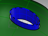
Option 2 - Use a patch surface to make the button
Next, you will create the button surface with the **Patch **command. Patch also support History. If Record History is on when the **Patch **command is used to create the button surface, changing the input surface will update the Patch surface.
-
Use the DupEdge command to duplicate the top edge of the surface.
-
Move the duplicated curve up in the World z-direction by a small amount.
-
Use Divide to mark off this curve with 50 points as before.
-
Use the PlaneThroughPt command with the selected points, and then delete the points like the previous exercise.
-
Use the CPlane command with the Object option to set the construction plane to the planar surface.
-
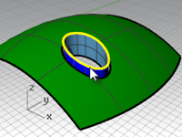
Make a circle or ellipse centered on the origin of the custom construction plane.
-
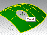
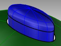
Use the Patch command, selecting the top edge of the button and the ellipse or circle.
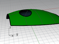
The surface is tangent to the edge and concave on the top.
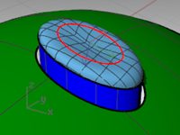
The size and vertical position of the circle/ellipse will affect the shape of the surface.
Note: If you recorded History for the patch, you can select the ellipse and move it up and down or scale it in two dimensions to modify the patch shape.
The Gumball control is perfect for making these adjustments. Make sure the Gumball alignment is set to CPlane. -
Hide this button top surface.
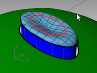
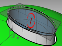
Option 3 - Use a rail revolve with line as the revolve axis and match surface
-
Use the DupEdge command to duplicate the top edge of the surface.
-
Move the duplicated curve in the World Z-direction a small amount.
-
Divide this curve with 50 points.
-
Create a surface withPlaneThroughPt as before. Delete the points like the previous exercise.
-
Use the CPlane command with the Object option to set the construction plane to the planar surface.
-
Use the **Lock **command (Edit menu: Visibility >Lock) to lock the surface created with PlaneThroughPt.
-
Use Line with the Vertical option to make a line of any convenient length from the origin of the construction plane down towards the button surface.
-
Use the Extend command (Curve menu: Extend Curve > By Line) to extend the edge at the seam through the rectangular surface. (If no seam is available use ExtractIsocurve to create a curve from the surface and extend.)
-
Use the Intersect command (Curve menu: Curve From Objects > Intersection) to find the intersection between the extended line and the rectangular surface.
-
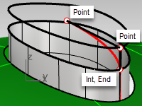
Use the Curve command to draw a curve from the end of the normal line, using the intersection point as the middle control point, to the end of the seam to use as a profile curve.
-
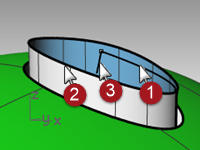
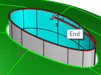
Start the RailRevolve command (Surface menu: Rail Revolve). Set the ScaleHeight option to Yes.
In general, setting ScaleHeight to Yes is helpful in this case where the rail curve is not planar. You will select the top edge of the extruded button as the rail. -
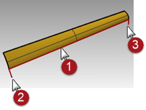
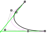
Select the curve you just created (1) as the profile curve, the top edge of the surface (2) as the path curve. Select the upper end of the vertical line (3) as one end of the revolve axis and the lower end as the other end of the revolve axis.
Next, the second point is directly vertical from the origin, and relative to the CPlane, (not the World cplane).
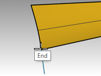
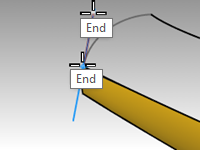
Optional Elevator Mode: Instead of creating the vertical line and picking the end points to specify the start and end of the revolve axis, use Elevator Mode.
At the prompt for Start of Revolve Axis, pick the end point of the profile curve with the **End **osnap.
Then hold down the Control key, again pick on the same end point on the profile curve.
Next, drag the cursor any distance away and pick the second point with the help of Elevator mode. This will input the revolve axis without your having to create a line.
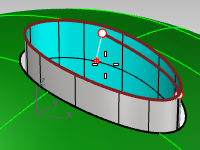
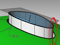
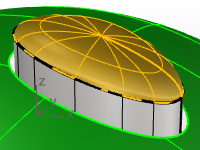
- RailRevolve does not pay attention to continuity during the surface creation.
You will need to match the new surface to the vertical sides of the button for tangency or curvature with the MatchSrf command .
In the **MactchSrf **dialog, set **Continuity **to Curvature, set **Preserve other end **to Postion, and set Isocurve direction adjustment to Automatic.
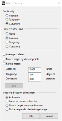
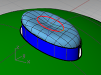
On close inspection, this seems to pinch at the top. **Undo **and try this **Match **again. - In the **MactchSrf **dialog, set **Continuity **to Curvature, set **Preserve other end **to Curvature, and set Isocurve direction adjustment to Automatic.
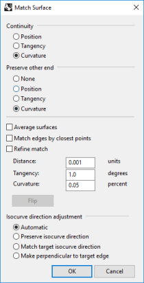
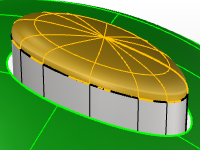
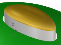
The continuity of the button surface looks better after MatchSrf with these settings.
Creased surfaces
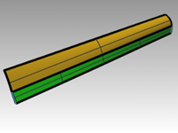
Often a surface needs to be built with a crease that may start at a particular angle and change to another angle or diminish to zero. The crease in the car body in the image is an example of this. The following exercise covers two possible situations.

Exercise 7-2 Surfaces with a crease (part 1)
The key to the following exercise is to get two surfaces that match with different continuity at each end. At one end, we will match the surface with a 10-degree angle, and at the other end, we will match the surface with tangency continuity. To accomplish this we will create a dummy surface at the correct angles and use this to match the lower edge of the upper surface. When the dummy surface is deleted or hidden, the crease appears between the two surfaces we want to keep.
Open and prepare the model
- Open the model Crease 01.3dm.
- Turn on the Curve and Loft layers.
- Make the Loft layer current.
- Use the Loft command to make a surface from the three curves.
The Loft command remembers the settings across sessions. Make sure the Loft style is set to Normal and Do not simplify.
- We are going to make a surface that includes all the curves but has a crease along the middle curve.
Use the middle curve to Split the resulting surface into two pieces. - Use the ShrinkTrimmedSrf command (Surface menu: Surface Edit Tools > Shrink Trimmed Surface) on both surfaces.
With a surface that results from a split at an isocurve, shrinking it will allow the edge to be an untrimmed edge because the trim corresponds to the natural untrimmed surface edge.
By trimming with a curve used in the loft, the curve is in effect an isocurve.
You can also use the Isocurve option in the Split command when the object to be split is a single surface.
- Hide the lower surface and turn off the Curve layer.
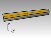
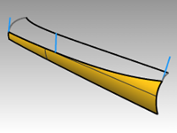
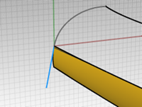
Create the dummy surface
We will change the top surface by matching it to a new dummy surface.
The dummy surface will be made from one or more line segments along the bottom edge of the top surface that are set at varying angles to it.
To get a line that is not tangent but is at a given angle from tangent, the easiest method is to use the transform tools to place the line tangent and then to rotate it by the desired increment.
- Make the Dummy Curve layer current.
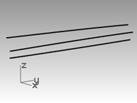
- In the Top viewport, draw a line 20 units long.
- Start the OrientCrvToEdge command (Transform menu: Orient > Curve To Edge).
- For the Curve to orient, select the line.
- For the Target surface edge, select the lower edge of the surface.
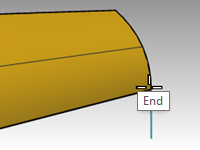
- For the Pick target edge point, change the command-line option to Copy=Yes, and snap to an endpoint of the edge.
- For the Pick target edge point, snap to the other endpoint.
- Press Enter.
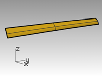
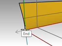
The result should look like the images above. - Next you will set a construction plane perpendicular to the lower edge of the surface.
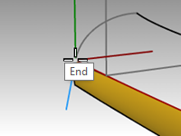
In the Perspective viewport, right-click the Viewport titleand off the menu select Set CPlane andthe Perpendicular to curve option. Snap to the left end point of the lower edge for the construction plane origin.
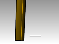
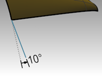
Set up the rail line
- Select the line segment at the left end and start the Rotate command.
- Set the center of rotation at the origin of the new custom construction plane.
- Rotate the segment 10 degrees.
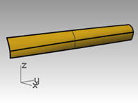
The result should be like the image on the right.
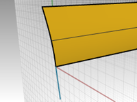
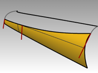
- Make the Dummy Surface layer current.
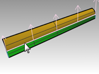
- Use the Sweep1 command (Surface menu: Sweep 1 Rail) to create the dummy surface.
- Select the lower edge of the upper surface (1) as the rail and the two line segments (2 & 3) as cross-section curves.
Make sure to use the surface edge and not the original input curve as the rail for the sweep.
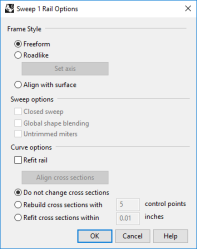
- In the Sweep 1 Rail Options dialog box, under Style, choose Align with surface.
This option causes the sweep surface to derive from the cross section curves its angle relative to the base surface at its edge. A shape curve tangent to the base surface will hold that tangency as it sweeps along the edge, unless another shape curve with a different angle to the surface is encountered, in which case there will be a smooth transition from one to the next

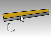
Match the surface to the dummy surface
- Use the MatchSrf command to match the upper surface to the dummy surface.
- Select the lower edge of the upper surface.
- Select the upper edge of the dummy surface.
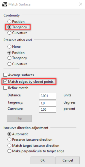
- In the Match Surface dialog box, choose Tangency and check the Match edges by closest points option.
This will keep distortion to a minimum.
- Show the lower surface and hide the dummy surface.
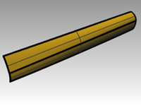
- Join the lower surface with the upper surface.
Because the surfaces are untrimmed, you have the option to merge the surfaces back into one surface.
The crease fades smoothly from one end to the other of the polysurface. If more control is needed over the angles of the crease, more segments can be placed to create the dummy surface.
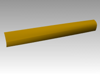
Surfaces with a crease - Part 2
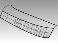
In this exercise, there is no convenient relationship between the crease curve and the surface. While similar to the other example, the upper surface is made with a two-rail sweep.
Exercise 7-3 Surfaces with a crease (Part 2)
Create a crease with trimmed surfaces
- Open the model Crease 02.3dm.
- Use the Line command (Curve menu: Line > Single Line) to draw a single line anywhere in the Top or Perspective viewport.
We will use this line to make a dummy surface.
- Use the OrientCrvToEdge command (Transform menu: Orient > Curve to Edge) to copy the curve for the dummy surface to the upper edge of the lower surface.
- Place a line at each end of the edge and somewhere in the middle of the edge.
- Move each line segment by moving its upper end to the lower end of the same segment.
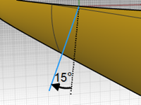
- Use the CPlane command (View menu: Set CPlane > Perpendicular to Curve) to set the construction plane to align with the line at the left of the surface.
- Use the Rotate command (Transform menu: Rotate) to rotate the line 15 degrees as shown in the illustration on the right.
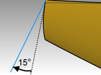
- Repeat these steps for the line in the middle of the surface.
Make the dummy surface
- Use the Sweep1 command to create the dummy surface.
- Select the upper edge of the lower surface as the rail and the three line segments as cross-section curves.
Use the Align with surface style for the sweep.
- Hide the original surface.
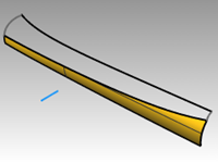
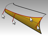
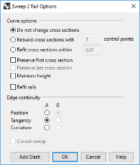
- Use the Sweep2 command to make the upper surface.
Select the upper edge of the dummy surface as a rail (1) and the long curve at the top as the other rail (2).
Select the curves at both ends as the cross-section curves (3) and (4).
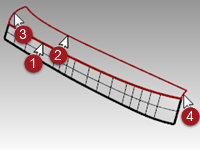
- In the Sweep 2 Rails Options dialog box, for the Rail continuity of edge A, choose Tangency.
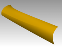
- Delete the dummy surface.
- Use Show or Show Selected (Edit menu>Visibility>Show selected) to show the original lower surface.
- Join the lower surface with the upper surface.
Input curve fairing to control surface quality
Curves in Rhino can come from many sources, they can be:
- Created in Rhino directly
- Imported from digitized data
- Imported from another application
- Section curves generated from a mesh
It is important to understand that many of these curves need to be optimized for quality.
Fairing is a technique used to simplify curves while improving their curvature graphs and keeping their shape within tolerance. It is especially important to fair curves that are generated from digitized data, intersections, extracted isocurves, or curves from two views.
Generally, curves that are single-span curves work better for this process. A single span curve is a curve that has one more control point than the degree. For examples a degree 3 curve with 4 control points, a degree 5 curve with 6 control points, or a degree 7 curve with 8 control points.
Analyze a lofted surface with curvature analysis
-
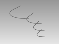
Open the model Fair Curves.3dm.
-
Select the curves and use the Loft command (Surface menu: Loft) with Style set to Normal and Cross-section curve options set to Do not simplify to make a surface.

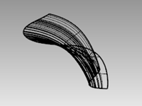
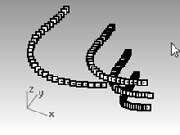
The surface is very complex. It has many more isocurves than are needed to define the shape, because the knot structures of the curves are very different.
The surface also has compound curvature.
-
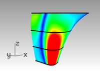
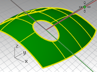
Select the lofted surface and start the CurvatureAnalysis command (Analyze menu > Surface>Curvature analysis).
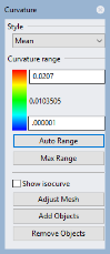
This creates a false color display using the same type of analysis meshes as the Zebra command.
The amount of curvature is mapped to a range of colors allowing you to analyze for areas of abruptly changing curvature or flat spots.
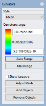
Choose Mean from the Style drop down.
This style is useful for showing discontinuities in the curvature—flat spots and dents. The mean is between the two curvature circle values at each point, mapped to a color value. -
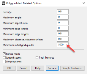
Click the AutoRange button.
-
Click the Adjust Mesh button and adjust the Minimum initial grid quads to have at least 5000 minimum grid quads to ensure a smooth display of the color range.
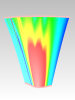
Note the streaky and inconsistent colors on the surface. This indicates abrupt changes in the surface.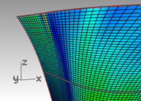
-
Undo or delete the lofted surface.
Rebuild the curves
-
Change to the Tangency Direction layer.
-
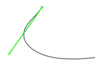
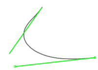
Use the Line command (Curve menu: Line > Single Line) with the Extension option, to make a line that maintains the tangency direction of an original curve from each end point and coming back towards the curve, any length.
Make the lines long enough to cross one another.
-
Change to Rebuilt Curves layer, and Lock the Tangency Direction layer.
-
Use the Rebuild command (Edit menu: Rebuild) to rebuild the curve.
-
Although there is a Rebuild option in the Loft command, rebuilding the curves before lofting them gives you control over the degree of the curves as well as the number of control points.
-
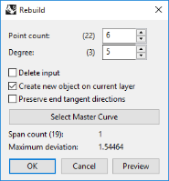
In the Rebuild Curve dialog box, change the Degree to 5 and the Point Count to 6 points.
-
Clear the Delete input option and check Create new object on current layer option.
-
Click the Preview button. Note how much the curves deviate from the originals.
This makes the curves into single-span curves. Single-span curves are Bézier curves. A single-span curve is a curve that has degree +1 control points. While this is not necessary to get high quality surfaces, it produces predictable results. -
Lock the Original Curves layer. We need to see these curves but we do not want to be able to select them.
-
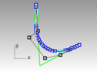
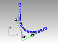
Select one of the rebuilt curves, and turn on the control points and Curvature graph.
-
Fair the curve by adjusting points until it matches the original curve closely enough.
-
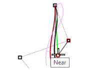
Start by moving the second point from each end of the rebuilt curve onto the tangent line. Use the Near object snap to drag along the tangent line.
-
Check the curvature graph to make sure the curve has smooth transitions.
The curves are fair when the points are adjusted so the rebuilt curves match the original locked curves closely, with good graphs. -
Fair the other curves the same way.
Here are some things to keep in mind when adjusting the curves:
- If you want to keep the curve tangent direction consistent with the original curves, make sure the second point from each curve stays on the green tangent direction line- only move these points with the Near object snap pulling the point onto the line.
- The DragMode command, set to ControlPolygon will constrain point dragging to the curve control polygon. You can use this tool to keep the tangent directions constant.
- Where possible, when fairing a set of curves to be used as input to a single lofted surface, try to keep the control point arrangement on each curve similar to the neighboring curves. This will help keep the surface nicely aligned.
- When control point adjustment becomes difficult due to the small movements needed, try using the Nudge keys to nudge the points by small amounts. See Help for more information about Nudge.
You can also use the Gumball to move points. When fine-tuning with very small point movements needed, you can set GumballDragStrength to something less than 100% to allow larger mouse movements to make small changes in the point locations.
Use PointDeviation to visualize the deviation while you edit the curves
- Make a Points layer and make it current.
- Select all of the original curves and start the Divide command (Curve menu: Point Object>Divide Curve by>Number of Segments). Set the Number of segments to 32 and GroupOutput=Yes.
- Deselect all objects, and select the grouped points.
- Start the PointDeviation command (Analyze menu: Surface>Point Set Deviation), and at the Select curves, surfaces, and polysurfs to test prompt, select the, roughly faired, rebuilt curves.
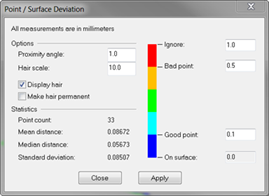
- When the Point/Surface Deviation dialog box pops up, set the numbers as follows:
Good point = 0.1
Bad point = 0.5
Ignore = 1.0
The display shows the deviation between the points displayed on the original curves and the closest locations to these on the rebuilt curves. - Lock the Points and the Original Curves layers.
- Continue to modify the rebuilt curves with the goal being that all points will turn blue, as good points.
Note: If you close the dialog box, you lose the display and you need to start over with PointDeviation.
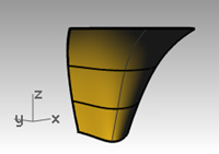
Make a surface with fair curves
- Loft the new curves.
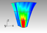
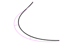
The shape and quality of the surface has very few isocurves but it is very close to the shape of the first surface.

- Analyze the surface with CurvatureAnalysis.
Note the smooth transitions in the false color display, indicating smooth curvature transitions in the surface.