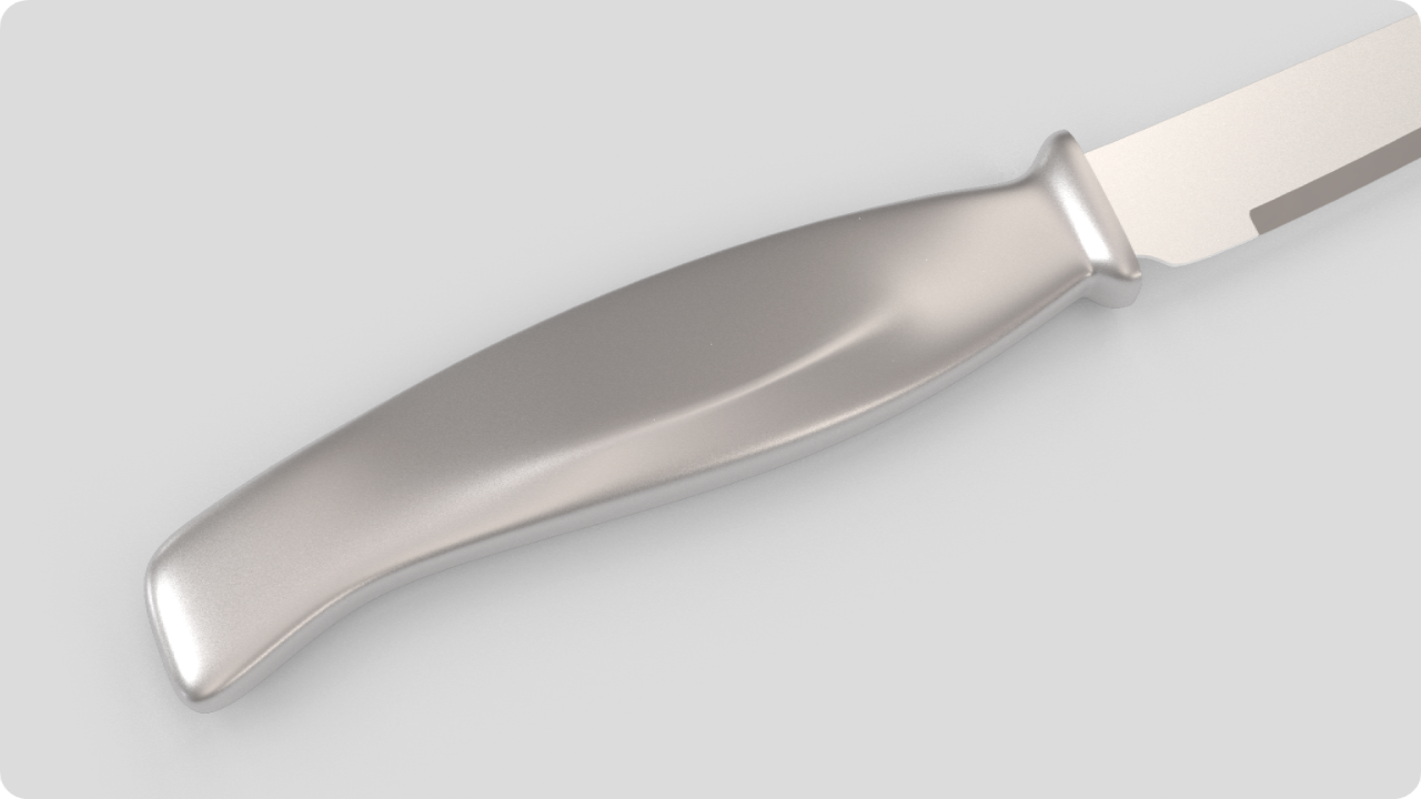
Real world products are made of flowing surfaces that are visually enriched with details such as fading chines, indents, bosses, chamfers, and so on. Breaking surface flow with feature lines that are then washed out into the continuous flow of a surface set is a common design intention that can be achieved in many ways.
In this tutorial, we will discover how to use the
![]() SubDCrease
command to help us create variable ‘weighted edges’, or softened creases along SubD edges. With this command, we can create a feature somewhere between a smooth edge and a creased edge without adding complexity to the SubD control net. Weighted edges have continuous surface tangent and curvature and are a good tool for making fillet-like features.
SubDCrease
command to help us create variable ‘weighted edges’, or softened creases along SubD edges. With this command, we can create a feature somewhere between a smooth edge and a creased edge without adding complexity to the SubD control net. Weighted edges have continuous surface tangent and curvature and are a good tool for making fillet-like features.
1. Preparing the Curves
Start by opening a Small Objects - Millimeters.3dm file by running the
![]() New
command. The first modeling step consists of creating the profile curves
viewport. We need three curves:
New
command. The first modeling step consists of creating the profile curves
viewport. We need three curves:
- The upper profile of the handle
- The middle curve that defines the washed-out crease
- The bottom profile of the handle
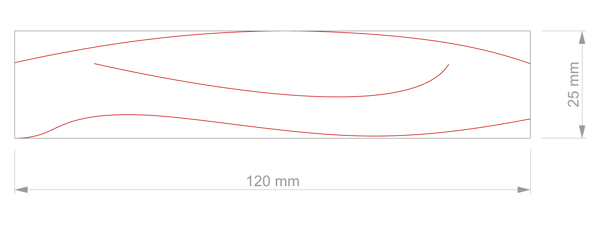
A curve is a freeform shape. To control its overall size, we can draw curves inside a rectangle that has the real size dimensions of our object. Run the
![]() Rectangle
command to create this bounding box. Place the First corner of rectangle at 0 so it is centered in the grid of the
viewport. Then set the length to 120 and the height to 25.
Rectangle
command to create this bounding box. Place the First corner of rectangle at 0 so it is centered in the grid of the
viewport. Then set the length to 120 and the height to 25.
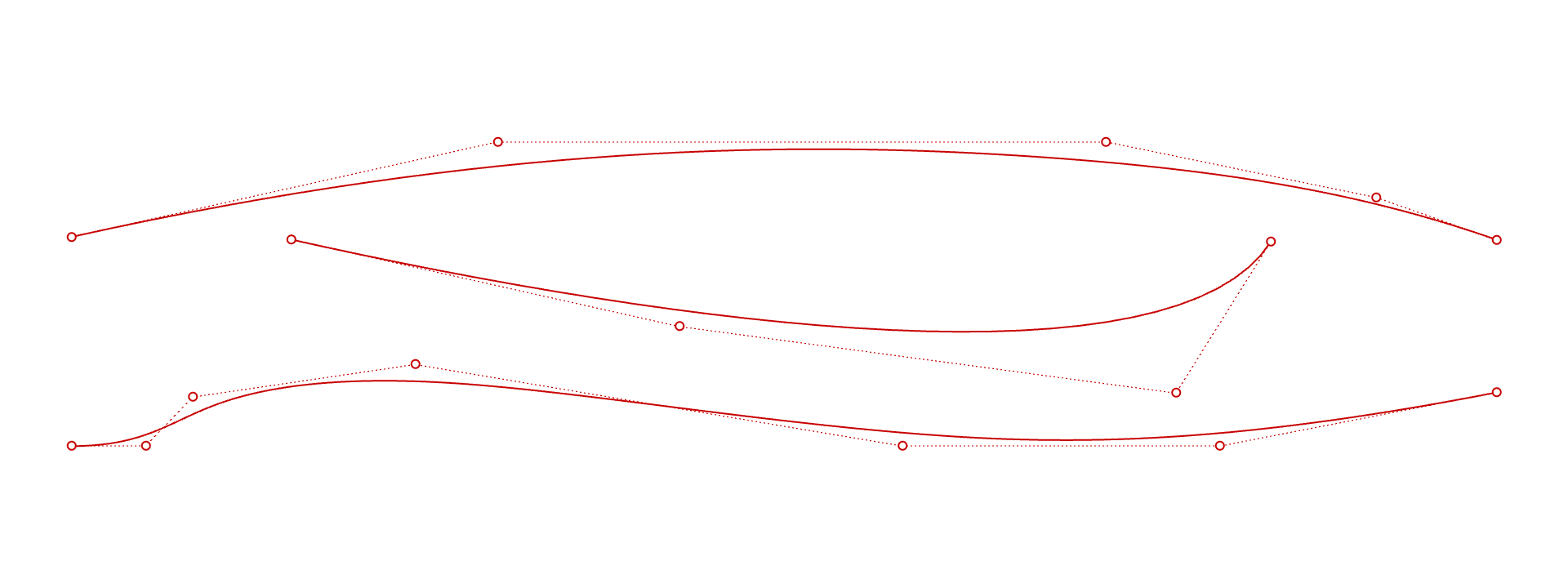
Use the
![]() Curve
command and follow the prompts. This command allows you to place points in space. They are called control points and they define the curve’s shape. Place the least amount of control points to obtain the desired shape.
Curve
command and follow the prompts. This command allows you to place points in space. They are called control points and they define the curve’s shape. Place the least amount of control points to obtain the desired shape.
2. Creating the Base Surface
We will use an intermediate step to get to the actual SubD handle, that consists of creating a dummy surface which we will later convert into a mesh (then a SubD) using the
![]() QuadRemesh
command. The reason is that this tool has built-in options that allow you to control the flow of the quads. So we can include the middle curve in the description of our object at an early stage.
QuadRemesh
command. The reason is that this tool has built-in options that allow you to control the flow of the quads. So we can include the middle curve in the description of our object at an early stage.
Run the
![]() Loft
command and select the upper and bottom curves only.
Loft
command and select the upper and bottom curves only.
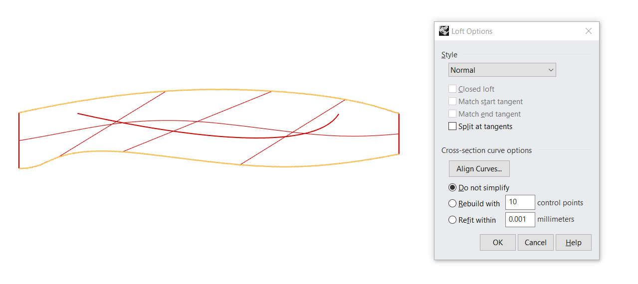
Maintain the default settings: Style set to Normal and under Cross-section curve options keep Do not simplify. Then click OK to validate.
In this step, we will convert the loft surface into a SubD while using our middle curve to influence how the SubD faces will flow. This flow will determine the shape of our crease. To this effect, select the loft surface and run the
![]() QuadRemesh
command. Make sure to map the following settings:
QuadRemesh
command. Make sure to map the following settings:
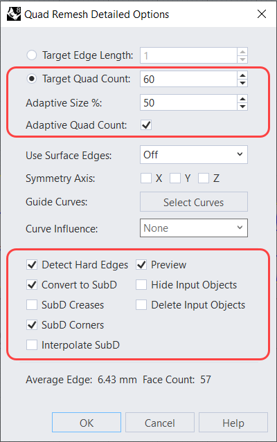
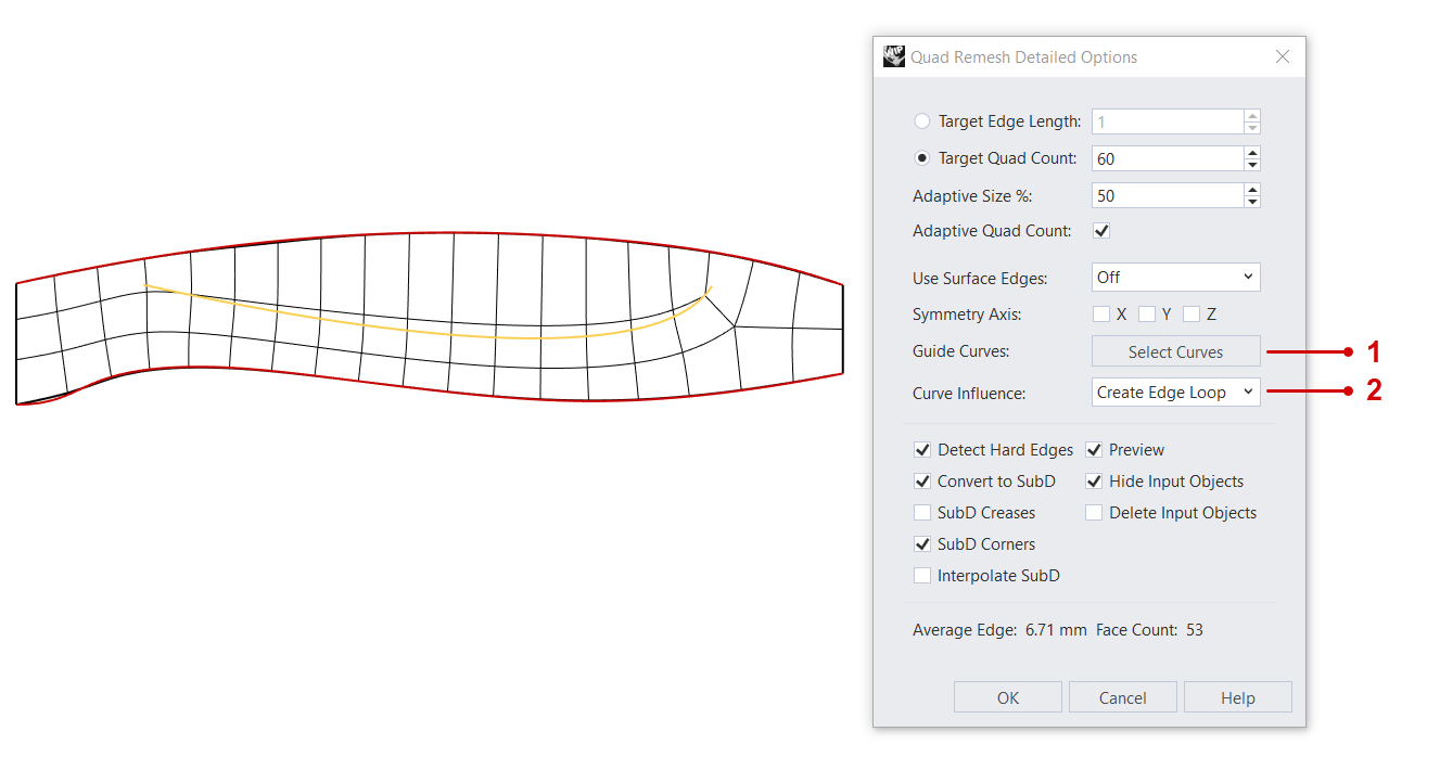
You might have to adjust the amount of Target Quad Count to obtain a better fit for your set of curves.
To bring the influencing curve into the process, click on 1 Select Curves. Pick the middle curve in the viewport. Then back in the dialog, by Curve Influence, select 2 Create Edge Loop.
3. Building the Main Body
Switch to the view. Click on Gumball on the Status Bar so it is active. Select the SubD. You’ll notice the Gumball Widget appears. Click on the Gumball Extrude Dot , type in 4, then press . We have just used the Gumball to extrude the SubD 4 units in height.
Let’s switch the viewport’s display mode to
Shaded
. You’ll notice the hard edges on the extruded SubD. To smooth these out, run the
![]() RemoveCrease
command. Double-click anywhere along the hard edge, to select the whole chain. Do the same for the second hard edge. Then press
.
RemoveCrease
command. Double-click anywhere along the hard edge, to select the whole chain. Do the same for the second hard edge. Then press
.
4. Tutorial Shortcut
5. Creating the Fading Crease
Now let’s get started with our fading creases! We will select a range of edges that roughly correspond to our initial middle curve. We can achieve this by sub-object selecting the first edge and double-clicking the last edge of our range.
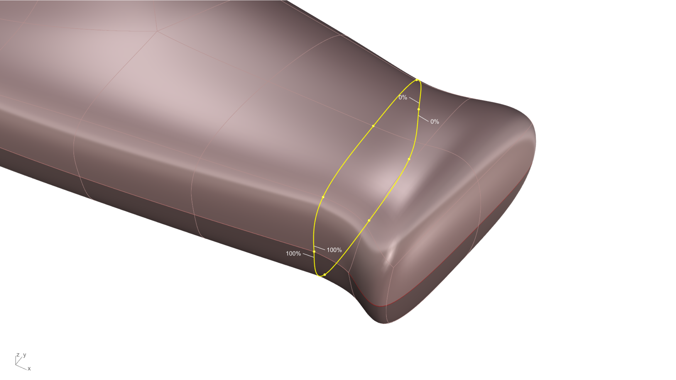
With our soon-to-be-creased edge selected, type the
![]() SubDCrease
command. You’ll notice points get highlighted all along, with a value of 0% at the start and end point. At this moment, you can dynamically click on any of these points and type weight values going from 0% to 100%.
SubDCrease
command. You’ll notice points get highlighted all along, with a value of 0% at the start and end point. At this moment, you can dynamically click on any of these points and type weight values going from 0% to 100%.
To select our modified edge again, select the SubD and type the
![]() SelSubDEdges
command. In the Command Line, make sure Weighted = Yes or click on it to toggle. Press
to validate. With the creased edge selected, enable the
Gumball
and click on the blue arrow to move the edge 2 units (in the vertical direction).
SelSubDEdges
command. In the Command Line, make sure Weighted = Yes or click on it to toggle. Press
to validate. With the creased edge selected, enable the
Gumball
and click on the blue arrow to move the edge 2 units (in the vertical direction).
At this point, feel free to select the soft crease edge or a portion of it and move it up or down to wash out or accentuate the effect.
6. Finishing the Main Body
We’ll finish the main body by mirroring it with a special SubD command…
To “mirror” the SubD, we will use the
![]() Reflect
command. This special mirroring command allows us to maintain symmetry of all forthcoming edits on both sides. To successfully place the reflection plane, the action must occur in the appropriate view or Cplane. Run the command while being in the
view. Select the SubD and click two points along the SubD edge to place the plane in the right orientation. You can also click on the XAxis option in the Command Line.
Reflect
command. This special mirroring command allows us to maintain symmetry of all forthcoming edits on both sides. To successfully place the reflection plane, the action must occur in the appropriate view or Cplane. Run the command while being in the
view. Select the SubD and click two points along the SubD edge to place the plane in the right orientation. You can also click on the XAxis option in the Command Line.
You’ll notice the reflected underside is slightly darker than the original side, indicating which is the child. Modify the original side and see how the child updates.
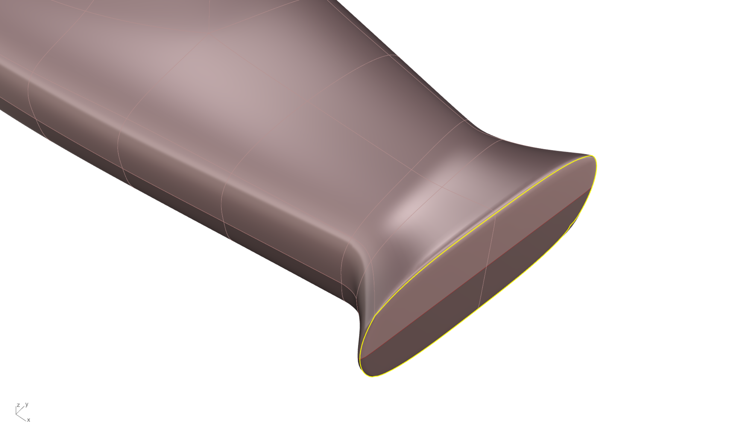
7. Sculpting the Neck
Let’s sculpt the “neck” area, where the blade insert would go…
We will start by sub-object selecting the top faces and extruding twice using the Gumball extrude handle .
We will now scale the selected faces in 3D using the Gumball scale handle . We’ll relocate the Gumball at the bottom of the extruded faces to rotate them around the Gumball’s XY rotate handle . This will give them a bit of an inclination.
We are at the point where we will add more creasing to the neck. Double-click on the edge corresponding to the first face we extruded. Run the
![]() SubDCrease
command and set your varying crease intensities by clicking on the highlighted vertex points as we did in Chapter 4.
SubDCrease
command and set your varying crease intensities by clicking on the highlighted vertex points as we did in Chapter 4.
You can use the
![]() Slide
command, moving the selection up and down to increase or soften the effect.
Slide
command, moving the selection up and down to increase or soften the effect.
To finish, we will add a constant crease to the top edge. It will make the area planar while adding a rounded transition at the intersection.
Sub-object select
the edge and run the
![]() SubDCrease
command. Click on the ConstantWeight option in the Command Line and set it to any value of your liking.
SubDCrease
command. Click on the ConstantWeight option in the Command Line and set it to any value of your liking.
You can continue sculpting the model using the same tools as above. Once done, remember to remove the reflection by selecting your SubD and running the
![]() Reflect
command. Then click on the RemoveExistingReflectSymmetry option in the Command Line.
Reflect
command. Then click on the RemoveExistingReflectSymmetry option in the Command Line.
Feel free to download the model’s final edition, which includes the blade and materials applied knife-final.3dm.
You can also experiment using other commands that soften or harden SubD edges. We recommend exploring the use of:
