This is an introductory tutorial for architects who want to learn about solid modeling workflows in Rhino. We will cover commands such as
![]() PushPull
,
PushPull
,
![]() SplitFace
,
SplitFace
,
![]() Inset
and the
Inset
and the
![]() Gumball
to complete the house.
Gumball
to complete the house.
Before we start
Let’s make sure we have set Rhino’s User Interface to a similar setup:
- Go to the Window menu
- Click on the submenu Window Layout
- Select Default Window Layout.
This will configure the toolbars and panels to the same setup and location as the one used in this tutorial.
Now go down by the Status Bar and make sure everything is disabled except for OSnap and Gumball, which should be enabled. On the left, by the Osnap Control , make sure Near and Cen are unchecked and End is checked. This is just to make our lives easier as we model.
As for the
![]() Gumball
make sure it is set to Snappy Dragging so it references all
OSnaps
we mentioned in the tutorial. You can set this in the Command Line options for the
Gumball
make sure it is set to Snappy Dragging so it references all
OSnaps
we mentioned in the tutorial. You can set this in the Command Line options for the
![]() GumballSettings
command.
GumballSettings
command.
Download and
![]() Open
the PP-Architecture-Start.3dm model.
Open
the PP-Architecture-Start.3dm model.
Facade and Wall Thickness
The file contains a simple box with some curves. We will start by using the
![]() PushPull
command to add and subtract volumes to the facade, that will give it a character look.
PushPull
command to add and subtract volumes to the facade, that will give it a character look.
- Run the
 PushPull
command and select the C-shape region on the top left. Press
and pull it out 2 units. Press
to end the command. Repeat the process for the recess located under the C-shape window (2 units inward).
PushPull
command and select the C-shape region on the top left. Press
and pull it out 2 units. Press
to end the command. Repeat the process for the recess located under the C-shape window (2 units inward).
-
Rotate the view to the underside of the object and run the
 Inset
command. Select the bottom surface as the surface to inset. For the Inset Distance type 0.1. Make sure the Split option at the Command Prompt is set to Yes. Then press
. This has created an internal face and the wall thickness.
Inset
command. Select the bottom surface as the surface to inset. For the Inset Distance type 0.1. Make sure the Split option at the Command Prompt is set to Yes. Then press
. This has created an internal face and the wall thickness. -
We can now sub-object select this inner face and use the Gumball Extrude Dot to extrude the face upward until we reference the End OSnap of the C-shape window corner.
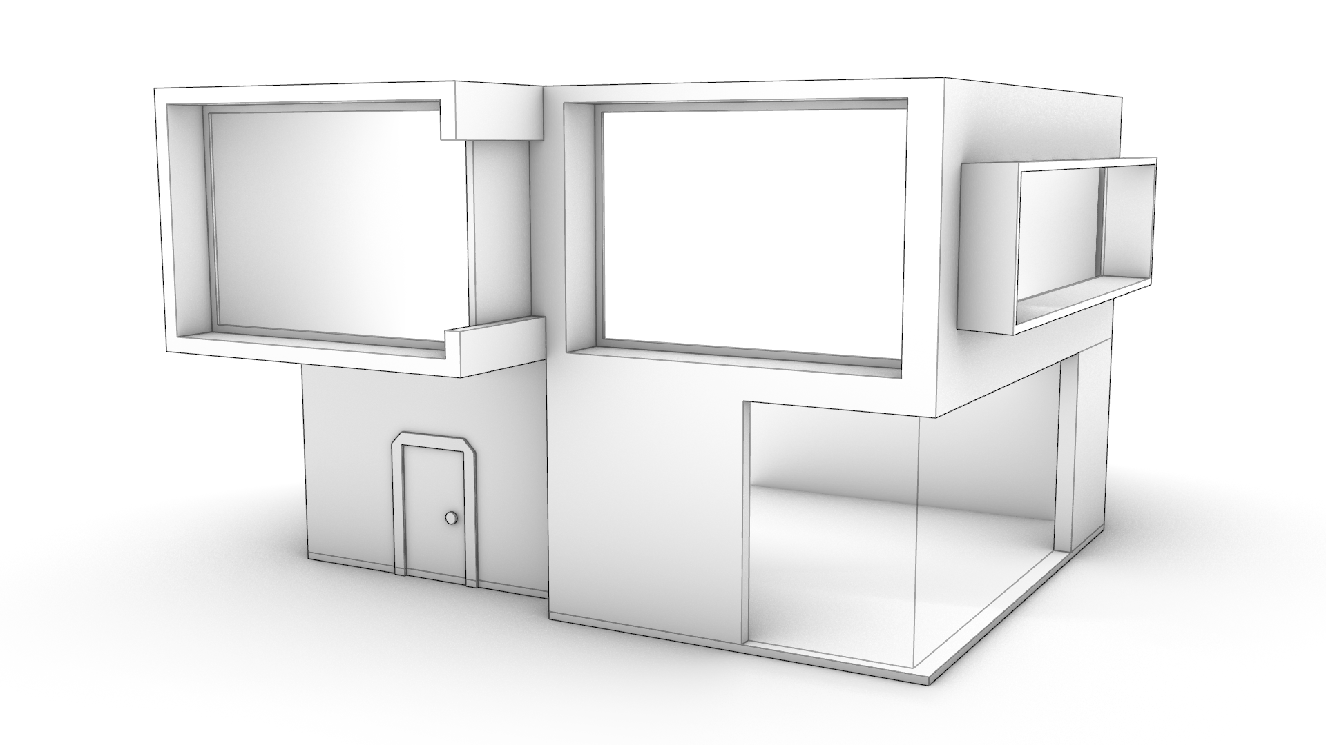
Creating the Facade Openings
We will proceed by punching holes into the facade, that represent the window openings.
-
Use
PushPull
to create the windows on the facade as follows:- Push the C-shape window on the top left of the facade until it cuts completely through the wall.
- Push the rectangle on the bottom right of the facade 9 units only.
- Push the rectangle on the top right of the facade until it cuts through the wall.
- Run the
 MergeAllCoPlanarFaces
command on the main volume to get rid of unnecessary edges left behind in the modeling process.
MergeAllCoPlanarFaces
command on the main volume to get rid of unnecessary edges left behind in the modeling process.
Adjusting the Roof and Outer Walls
We’ll now give the roof a bit of a slant and learn how to extend using the
![]() Gumball
.
Gumball
.
-
Run the
PushPull
command and select the surface representing the roof. Pull it upward 0.5 units. -
Sub-object select the back edge of the roof and use the Gumball Arrow to drag it upward in the Z direction (usually represented by the Gumball’s blue arrow) by 0.8 units. This will give an inclination to the roof surface from back to front.
- We will sub-object select the back wall and use the Gumball extend functionality. You can do this by pulling on the Gumball Extrude Dot while holding down . This activates the Gumball Extend functionality.
Gumball’s extend functionality appears as a halo that surrounds the extrude dot. It becomes available under certain circumstances only:
- The Gumball must be aligned to the surface.
- At least one of the adjacent surface’s needs to be tapered.
- It only works on planar geometry.
If all of the above is true, make sure to press the Shift key to extend as opposed to extrude!
Adding the Side Wall Elements
As part of the design, the side wall has a window and a balcony with a front glass barrier. We’ll use the
![]() Gumball
’s different tools to create these parts.
Gumball
’s different tools to create these parts.
- Close to the right wall, you’ll see a set of black curves. Select the larger rectangle. Then using the Gumball Cut Handle , push it through the wall. This will create an opening in the solid that represents our window opening.
- Select the U-shape curve underneath the large rectangle. We will use this curve to create the balcony. Pull on the Gumball Cut Handle while pressing down until you hit the wall by referencing an End OSnap on the wall. The Gumball Cut Handle + key combination is a shortcut to booleaning, using a simple closed curve (the U shape curve) + a solid (the house).
- We will create the front barrier for the balcony. First let’s change to the Windows layer in the
 Layer
Panel.
Zoom in on the balcony floor to find a long and slim rectangle lying on the floor’s surface. Select it and pull on the
Gumball Extrude Dot
in the Z direction (usually the blue dot).
Layer
Panel.
Zoom in on the balcony floor to find a long and slim rectangle lying on the floor’s surface. Select it and pull on the
Gumball Extrude Dot
in the Z direction (usually the blue dot).
We extruded this as an independent element from the balcony itself. This will allow us to apply a different material to it when configuring the model for visual purposes. In fact, since it’s on the Windows layer and that layer has a Glass material assigned to it, this extrusion will inherit that material when rendered.
Creating the Window Panes
Now that the window openings are created, we can add the surfaces for the glass panes.
-
While still in the Windows layer, sub-object select the two edges representing the L-shape opening at the bottom right. Then extrude it using the Gumball Extrude Dot until you reference the opposite top edge. These are the actual window doors for this side of the house.
-
Let’s navigate towards the C-shape window. Select the rectangle we originally used to punch this window hole. Now, run the
 PlanarSrf
command. Using the same technique create the window for the top right opening. We have now added two independent surfaces for our house openings.
PlanarSrf
command. Using the same technique create the window for the top right opening. We have now added two independent surfaces for our house openings.
Making the Ground Floor
Let’s add the main floor slab. We’ll do this by duplicating the footprint of the house into a curve and extruding it into a solid.
-
Change back to the Main layer in the
Layer
Panel. -
Now sub-object select the underlying surface of the walls. Then run the
 DupBorder
command. You should obtain two curves: a closed loop representing the inner border of the wall and one representing the outer border.
DupBorder
command. You should obtain two curves: a closed loop representing the inner border of the wall and one representing the outer border. -
Select the outer closed curve only. Click inside the Gumball Extrude Dot , and type 0.3 or -0.3 depending on the arrow’s direction.
Modeling the Entrance Door
Let’s focus on creating the main door. We’ll introduce a new functionality called
![]() AutoAlignCPlane
. It’s a quick way of adapting the CPlane (our drawing plane) orientation to an existing geometry, allowing us to place our curves in the right position and location. This tool is a great companion to
AutoAlignCPlane
. It’s a quick way of adapting the CPlane (our drawing plane) orientation to an existing geometry, allowing us to place our curves in the right position and location. This tool is a great companion to
![]() PushPull
.
PushPull
.
- Activate the AutoCPlane down by the Status Bar . Then sub-object select the recessed surface on the facade.
Note: For the purpose of the above visualization, I temporarily changed the Display Mode to Wireframe .
-
Let’s learn how to use
 SmartTrack
to reference points and distances on the existing geometry. This will help us place new geometry aligned and in the right location. We’ll do it step-by-step:
SmartTrack
to reference points and distances on the existing geometry. This will help us place new geometry aligned and in the right location. We’ll do it step-by-step:-
Activate SmartTrack down by the Status Bar .
-
Run the
 Rectangle
command.
Rectangle
command. -
Make sure the End OSnap is checked and the Near OSnap is unchecked.
-
Mouse hover over the bottom left corner, until the End OSnap is detected. Without clicking, drag your mouse towards the surface, following the bottom edge. You’ll see a gray tracking line activate and a blue point appear at the corner of the surface.
-
At this point, type 2 in the Command Line at the First corner of rectangle prompt.
-
Result: The first corner of our rectangle should be placed 2 meters from the bottom left corner of the facade.
-
At the Other corner or length prompt, type 1.8 and press . Then type 2 and press to end the command.
 The Curve for the Door is 1.8 x 2 mts
 -
-
Use this curve to create the door opening using the
PushPull
command. -
Sub-object select the 3 edges of the door. Then run the
 Offset
command. At the Command Prompt set the Distance to 0.3 and click outside the door at the Side to offset prompt. We have duplicated these 3 edges as curves that lie on the facade surface.
Offset
command. At the Command Prompt set the Distance to 0.3 and click outside the door at the Side to offset prompt. We have duplicated these 3 edges as curves that lie on the facade surface. -
Run the
PushPull
command and click in this region, representing the door frame. Pull outward to a distance of 0.1.
- Voila our concept model! A little different than our initial design intention.
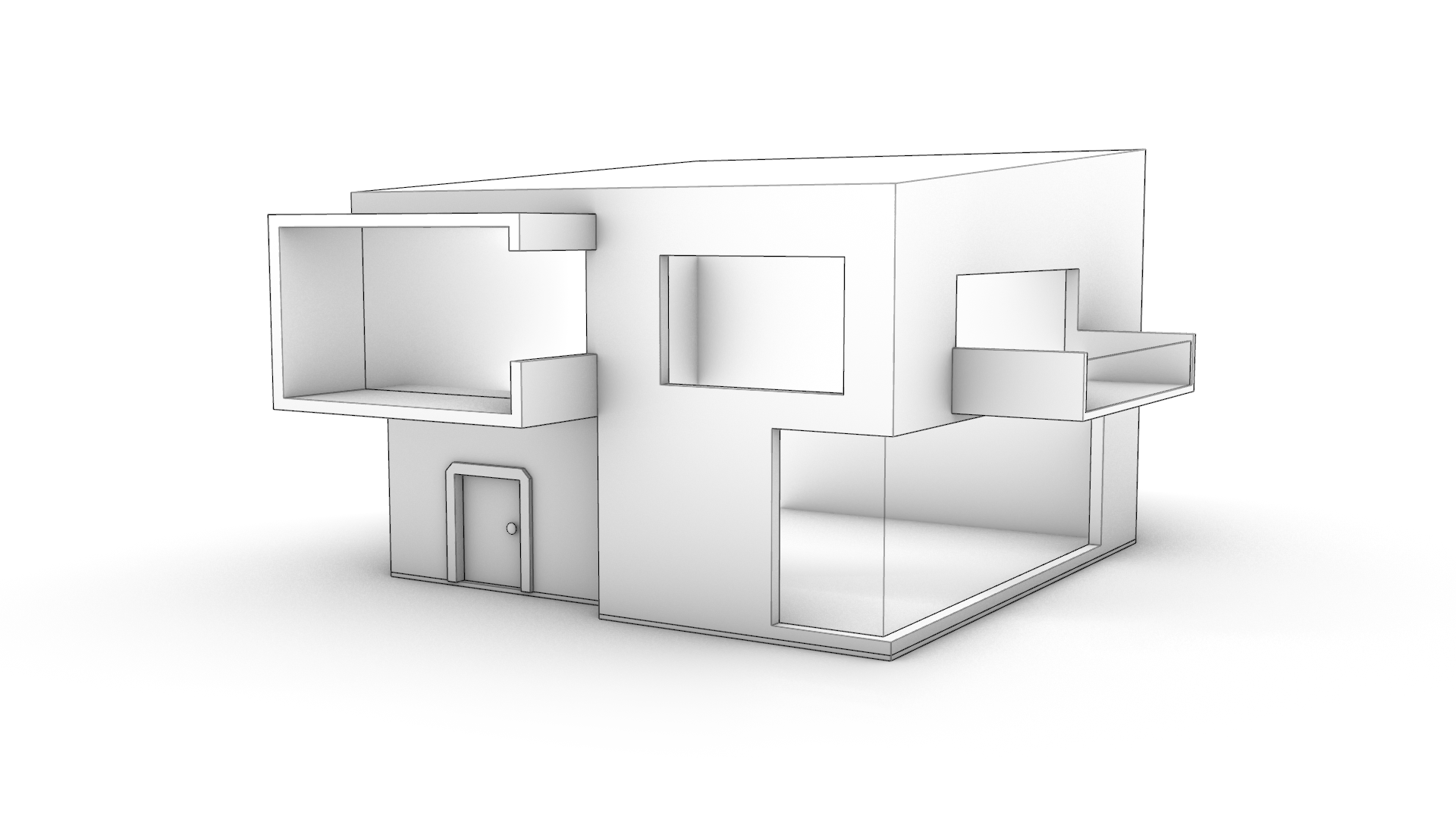
Feel free to download the completed PP-Architecture-Final.3dm model.
Learn More
Visit our PushPull page to learn more about the Modeling Simplified suite in Rhino 8.
Intro to PushPull in Rhino
Learn about PushPull, a sturdy way of solid modeling in Rhino. It can add or remove volumes from existing geometry, including curved shapes.
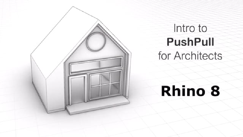
PushPull for Architects
Use some of Rhino 8's new tools such as PushPull, Gumball, Inset or AutoAlignCplane to achieve faster results when working with rectilinear geometry.
