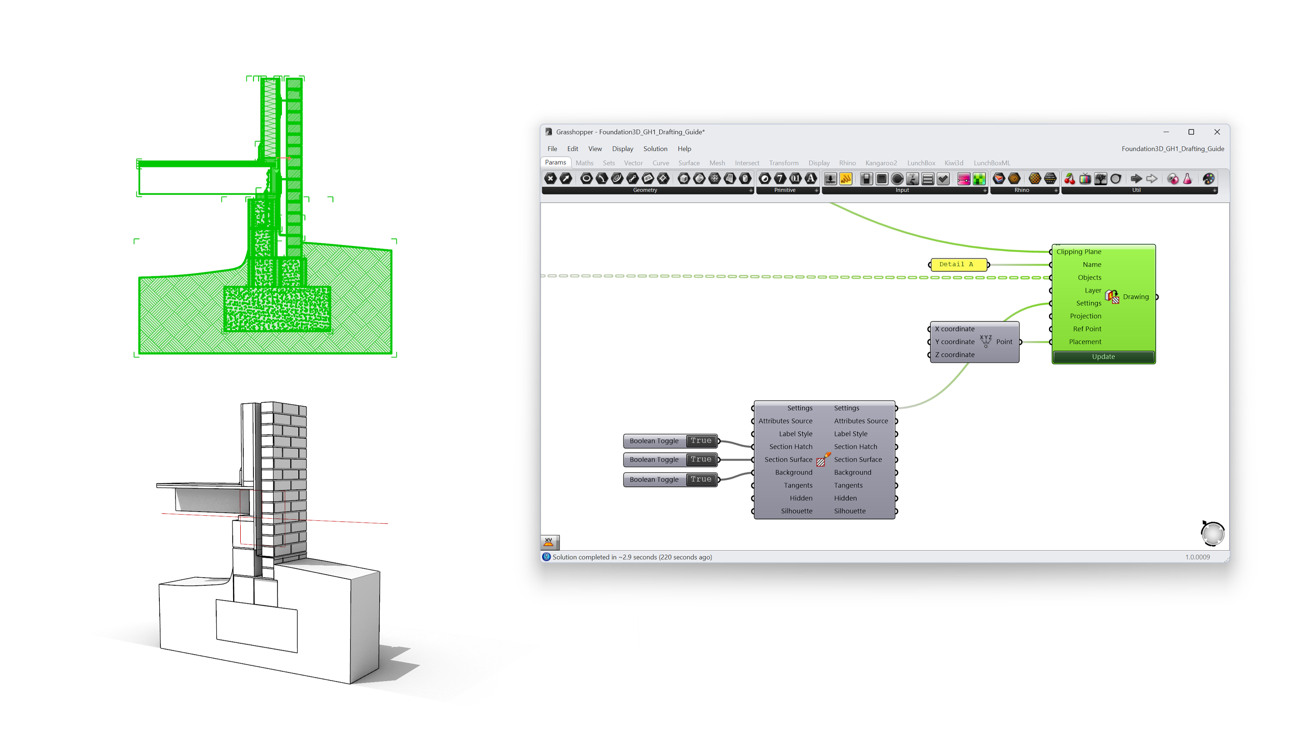
In this tutorial, learn how to add hatch patterns and create a parametric section using
 Grasshopper
's new drafting components on a wall construction detail 3D model.
Grasshopper
's new drafting components on a wall construction detail 3D model.
 asdfsdfsdf
The problem this workflow solves
 Query Model Object
activate the Gumball
Query Model Object
activate the Gumball
Architects and BIM specialists model construction details in 3D, but the deliverable is almost always a 2D drawing: a section through the wall assembly with the correct material hatches (insulation, concrete, brick, sealant) placed on the right layers, at the right scale.
Traditionally this meant running  Make2D
or
Make2D
or  ClippingDrawings
, then hatching by hand. Every time the detail changed, whether a thicker insulation layer or a different slab height, the drawing had to be redone.
ClippingDrawings
, then hatching by hand. Every time the detail changed, whether a thicker insulation layer or a different slab height, the drawing had to be redone.
With Rhino 9, the entire section workflow lives in Grasshopper
1. Sections become parametric: move a slider and the clipping plane moves, the 2D drawing regenerates, and the hatches follow. Custom hatch patterns are no longer hand-edited .pat files but Grasshopper definitions you can preview, adjust, and export as new .pat files.
What you will learn
- How to create and control a clipping plane from the Grasshopper canvas, and limit it to specific objects and layers.
- How to extract a live 2D clipped drawing (section curves, hatches, background linework) that updates when the model changes.
- How to build a custom hatch pattern parametrically and apply it to the section.
- How to browse and filter hatch patterns with the Value Picker.
- How to inspect hatches, geometry, and non-geometry data on the canvas with the Content Viewer.
Prerequisites: Rhino 9, basic Grasshopper knowledge (placing components, wiring parameters). Download the model Foundation3D.3dm and the Grasshopper definitions for each section.
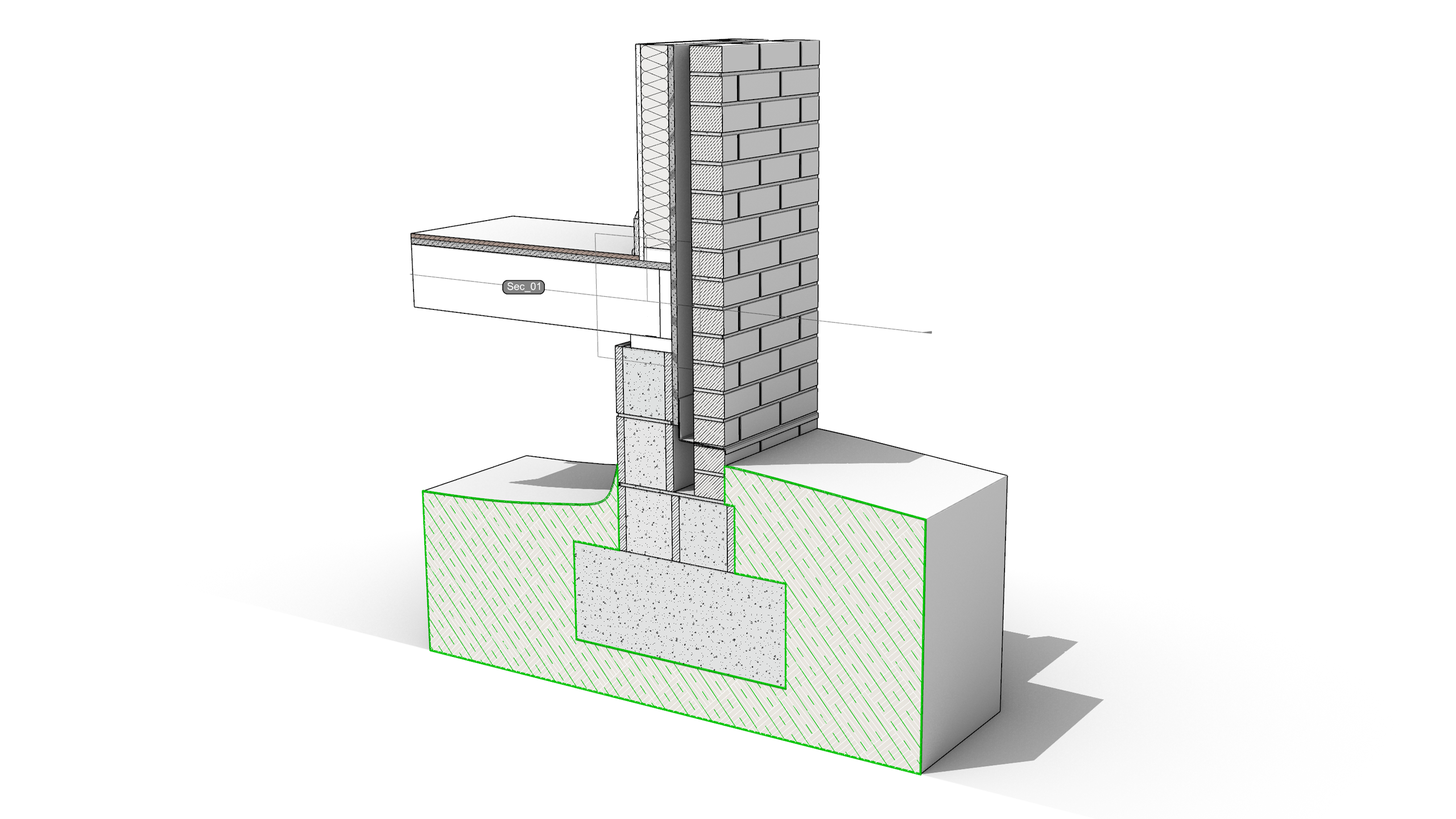
1. The model: a wall construction detail
The example model is a typical exterior wall detail: a concrete foundation with a CMU, a floor slab, a wood stud wall system with an air cavity, and a brick veneer. Each building element sits on its own layer, and section styles are assigned per layer so that every material can carry its own hatch when sectioned.
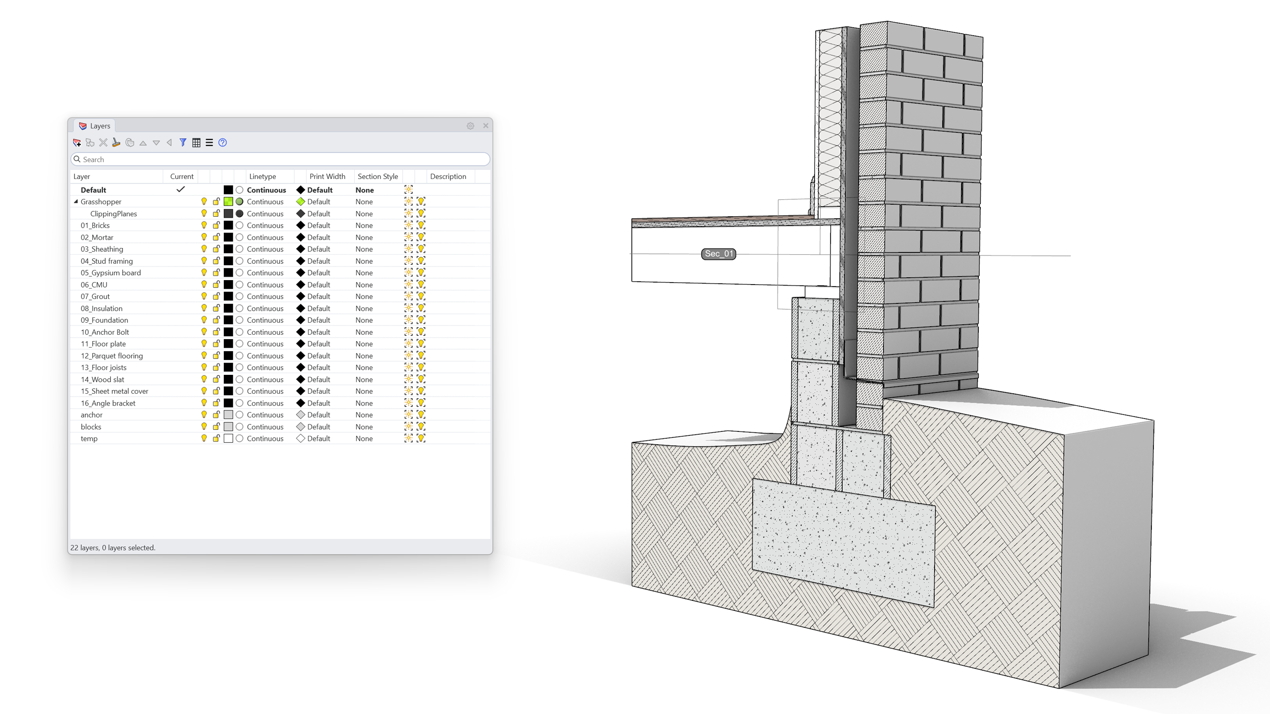
This layer organization is the backbone of the workflow. The new Grasshopper components respect Rhino’s Section Styles (the hatch pattern, boundary settings and colors you assign to objects or layers), so the time invested here pays off in every drawing extracted later.
Tip: If you are starting from your own model, assign section styles in Object Properties > Section Style or per layer in the Layers panel before moving to Grasshopper.
2. Creating a parametric clipping plane
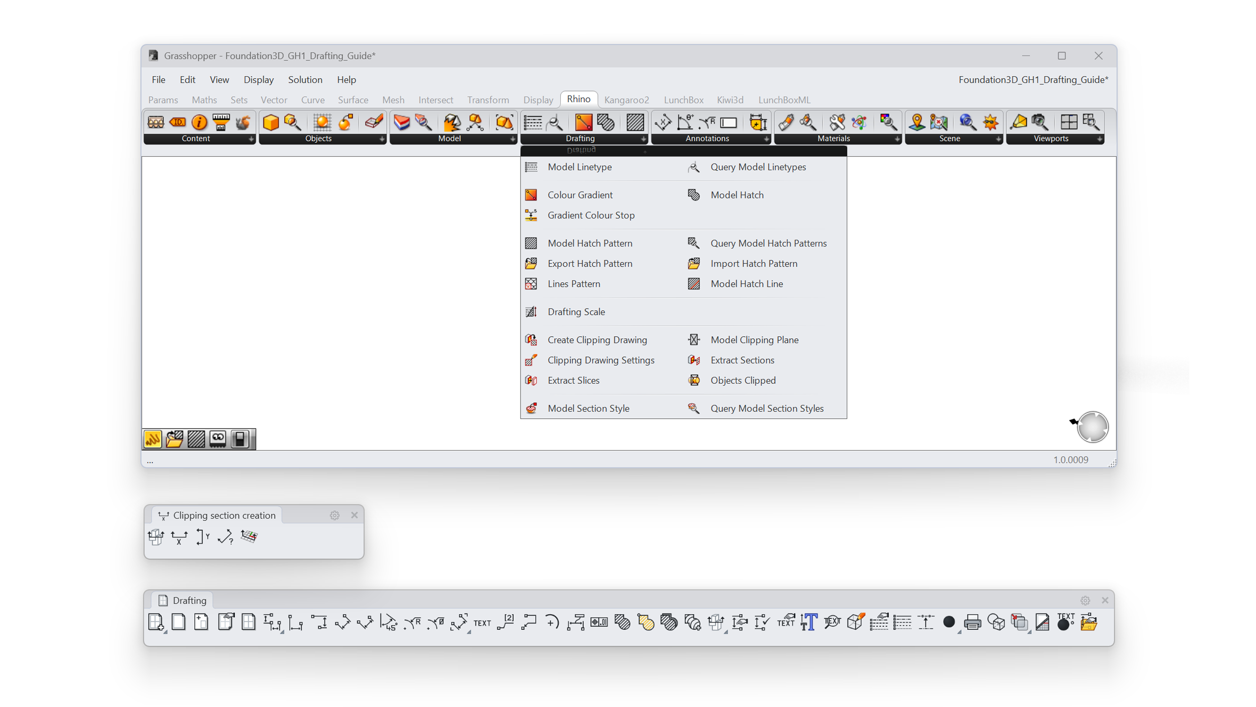
All new clipping components live in the Rhino tab, Drafting subcategory of the Grasshopper canvas.
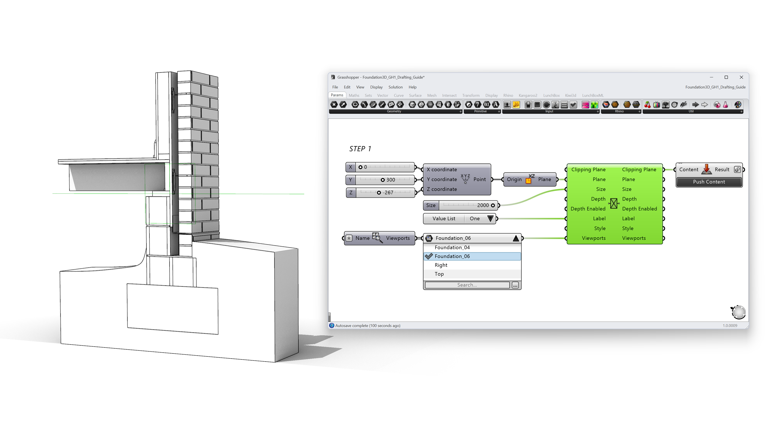
Start by placing a Model Clipping Plane component. Rather than referencing an existing clipping plane from the document, we build one from scratch so every property stays parametric:
- Plane sets the position and orientation of the section cut. Feed it an XY Plane whose origin is driven by a Number Slider: this slider becomes the “section height” control for the whole detail.
- Size and Depth set the width and depth of the clipping plane. Make sure the plane extends past the full wall assembly; geometry outside the plane’s extents will not appear in the extracted drawing.
- Label and Style define how the section marker is annotated (None, Annotation Dot, Text).
- Viewports sets which viewports the plane clips. Wire in a Query Viewports component; with an empty name filter it returns all model viewports.
To name the section (“Detail A”, for example), pass the clipping plane through a Model Object component, exactly as you would name any other model object in Grasshopper.
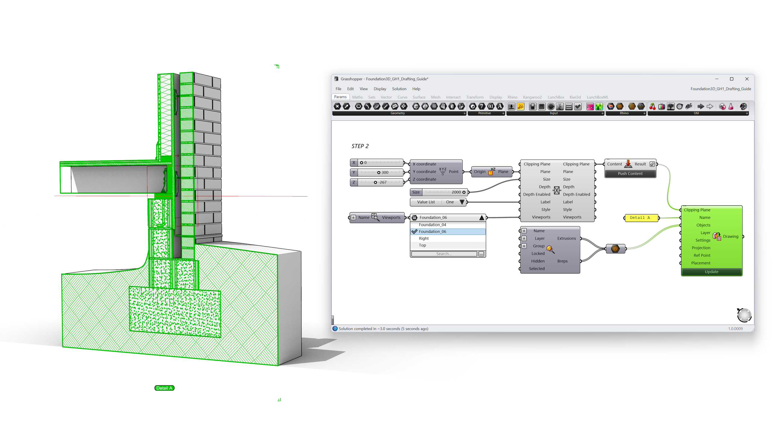
Drag the slider. The wall assembly clips live in the viewport. This is already a parametric section, before a single line has been drawn.
When the clipping plane should become part of the document, to use it in layouts or share the file, bake it with a Content Cache component. By default a baked clipping plane clips all objects in the model.
3. Controlling what gets clipped
A construction detail often includes context you don’t want to cut: an annotation scale figure, existing structure, or reference geometry. The Objects Clipped component controls this:
- Clip Filter offers (0) All, (1) Include Selected, or (2) Exclude Selected.
- Objects / Layers are the objects or layers to include or exclude.
Set the filter to Exclude Selected (2) and wire in the Context layer: the wall assembly is sectioned while the surrounding geometry stays whole.

Note: The Objects and Layers inputs must reference content that exists in the Rhino document (it must have an ID). Grasshopper-only geometry needs to be baked first, and Content Cache handles this cleanly.
Option B: filter upstream, feed geometry straight into the drawing
Objects Clipped works on a baked clipping plane inside the Rhino document. If you’d rather keep everything parametric and skip the bake step, do the filtering upstream in Grasshopper and feed the selected geometry directly into the Objects input of Create Clipped Drawing (see Chapter 4). Unlike Objects Clipped, that input happily accepts plain Grasshopper geometry, so nothing needs an ID in the document.
The definition mirrors the layout above:
- Build the object selection separately. Type the layer name pattern into a Layers parameter (or a text panel) and query the document with a Query Model Layers component. Pipe the result into a Value Picker so the layers appear as a checklist on the canvas. In the picker, tick only the layers you want to cut, in this example
08_Insulation,11_Floor plate, and12_Parquet flooring. - Pass the picked layers through a Content component (Parent / Name / Tags) and then a Query Model Objects component with the Layer input driven by the picker. Its Extrusions and Breps outputs give you exactly the geometry sitting on those layers, still fully referenced but ready to travel through Grasshopper as data.
- Wire that geometry into the Objects input of Create Clipped Drawing, alongside the clipping plane from step 1 and your Clipping Drawing Settings. Press Update (or expose the Update input) to generate the 2D drawing.
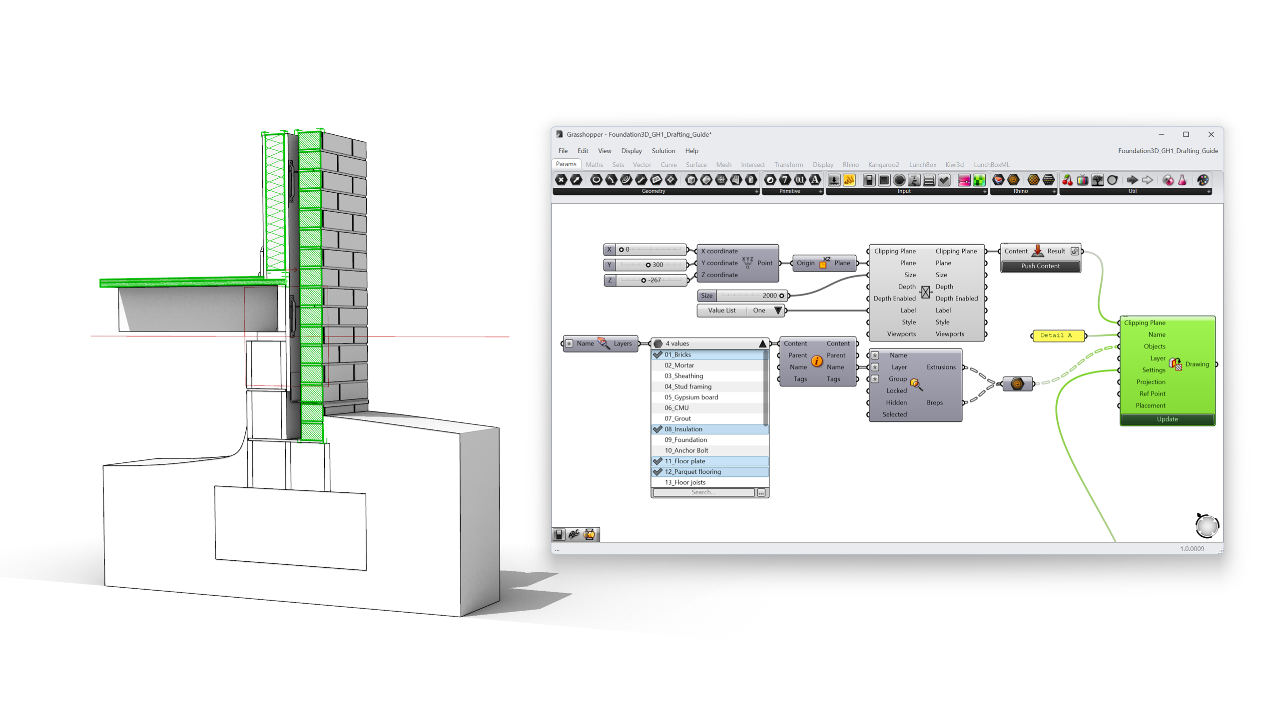
4. Extracting the 2D section drawing
Clipping the view is presentation; a deliverable needs linework. The Create Clipped Drawing component, the Grasshopper equivalent of Rhino’s _ClippingDrawings command, extracts section curves, hatches, and background geometry into a 2D drawing stored as a block.
Its companion, Clipping Drawing Settings, decides what the drawing contains:
- Attributes Source: By Output Layers creates a clean, automatically structured layer tree under a root layer named after the clipping plane; By Source Layers keeps the original object attributes; By Input Objects combines both.
- Section Hatch / Section Surface include the material hatches and fills cut by the plane.
- Background, Tangents, Hidden, Silhouette control which edge types beyond the cut appear in the drawing.
For a construction detail, enable Section Hatch and Background, and set attributes By Output Layers. Every extracted drawing then arrives pre-organized for layout work.
Wire the settings into Create Clipped Drawing together with:
- Clipping Plane: the plane from Chapter 2.
- Objects: the geometry to include. Unlike Objects Clipped, this input accepts plain Grasshopper geometry; nothing needs to be baked.
- Placement: a target plane for the 2D drawing. Leave it empty to draw the section in place on the clipping plane, or give it a plane next to the model to lay the drawing flat for a sheet.
- Update: drawing extraction can be heavy, so the component recalculates only when you press the Update button. Zoom into the component and click the + to expose Update as a Boolean input if you want automatic regeneration, which is useful with Grasshopper Player.
Move the section slider, press Update, and the 2D detail regenerates: cut lines, hatches, and background edges, on structured layers. This is the moment the workflow becomes parametric documentation.
5. Creating material hatch patterns
The extracted drawing picks up hatches from the section styles in the document. But what if the pattern you need doesn’t exist? Rigid insulation, for instance, is often drawn with a pattern that isn’t in the default library.
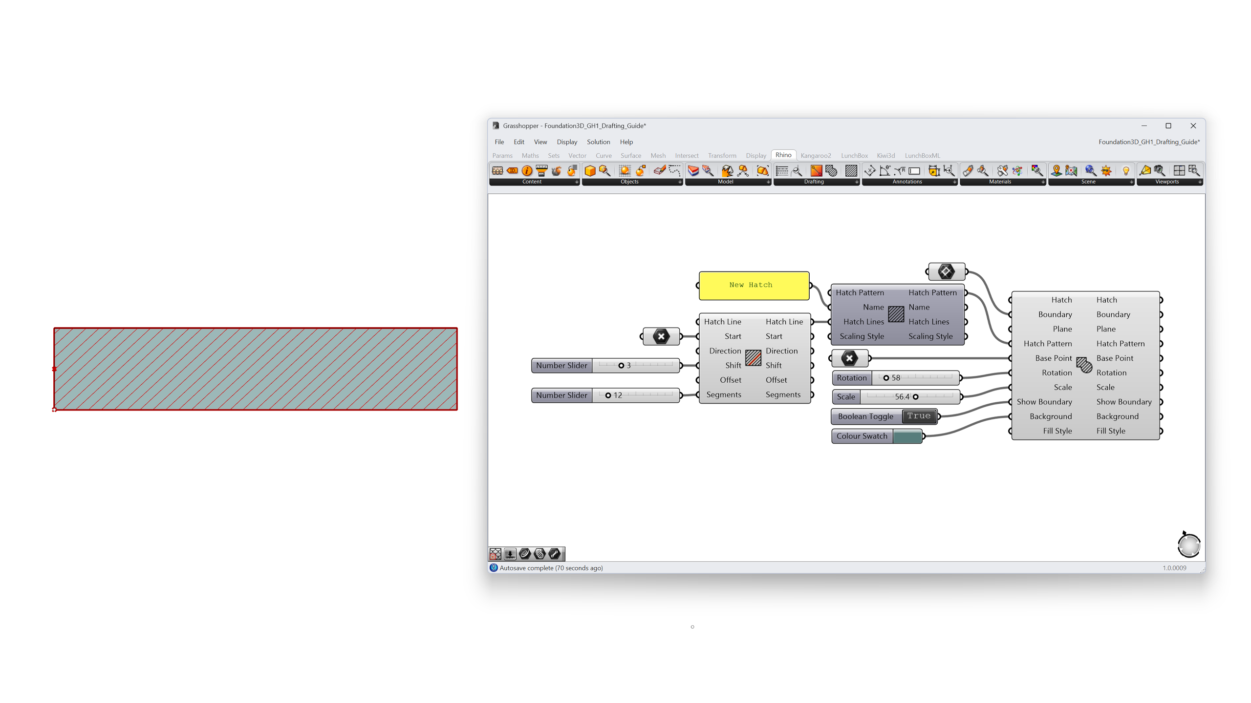
Previously, custom patterns meant hand-editing .pat files in AutoCAD’s text syntax with no live preview. In Rhino 9, hatch patterns are Grasshopper data:
- Model Hatch Pattern is the pattern definition itself: name, description, units, scaling style (Drafting patterns scale with the plotted drawing; Model patterns have a fixed real-world scale, like actual brick coursing).
- Model Hatch Line is one family of parallel lines in a pattern: a start point, direction, offset between repetitions, and a segments list for dashes (positive values are solid, negative are gaps).
- Model Hatch is an instance of a pattern inside a boundary curve, ready to preview or bake.
Build a new pattern from solid Hatch Lines, at a 45° direction, and feed it into a Model Hatch Pattern. Wire a rectangle into a Model Hatch to preview the result live while you tune the offsets with sliders.
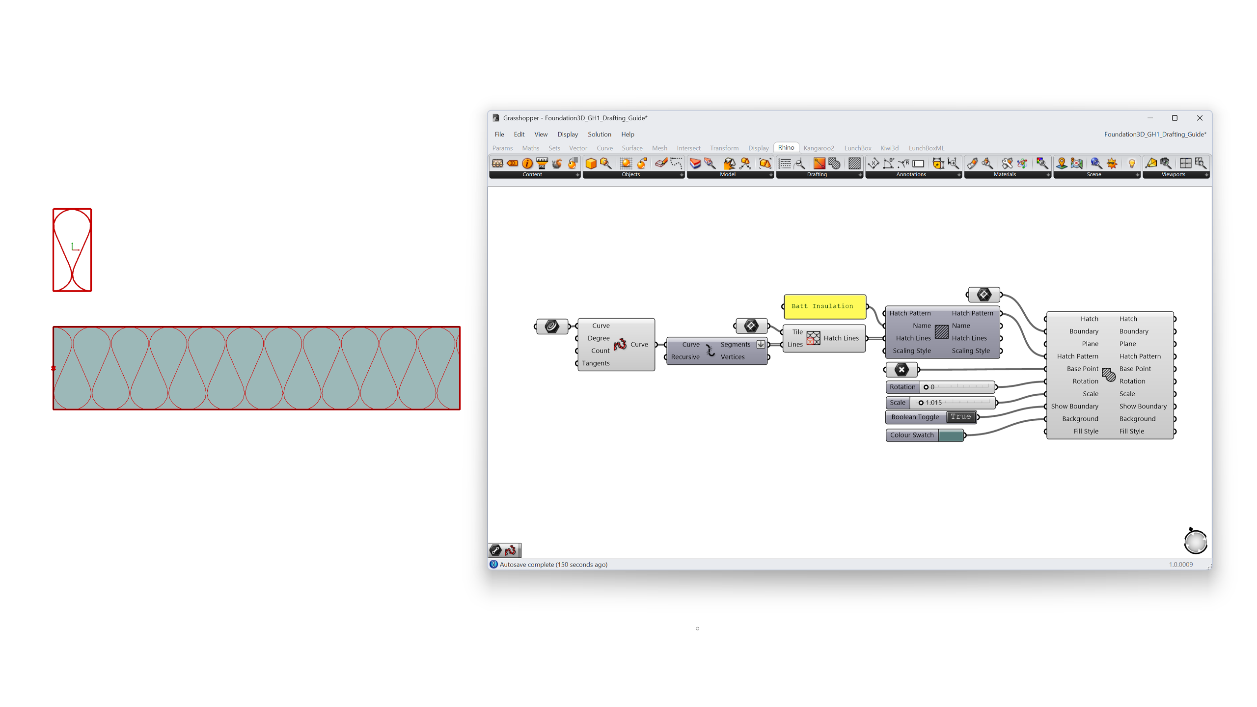
For patterns that are easier to draw than to describe, such as brick bonds, stone patterns, or batt insulation, use the Lines Pattern component instead. Draw the line segments inside a rectangular tile, feed both to the component, and it repeats the tile across the hatch area.
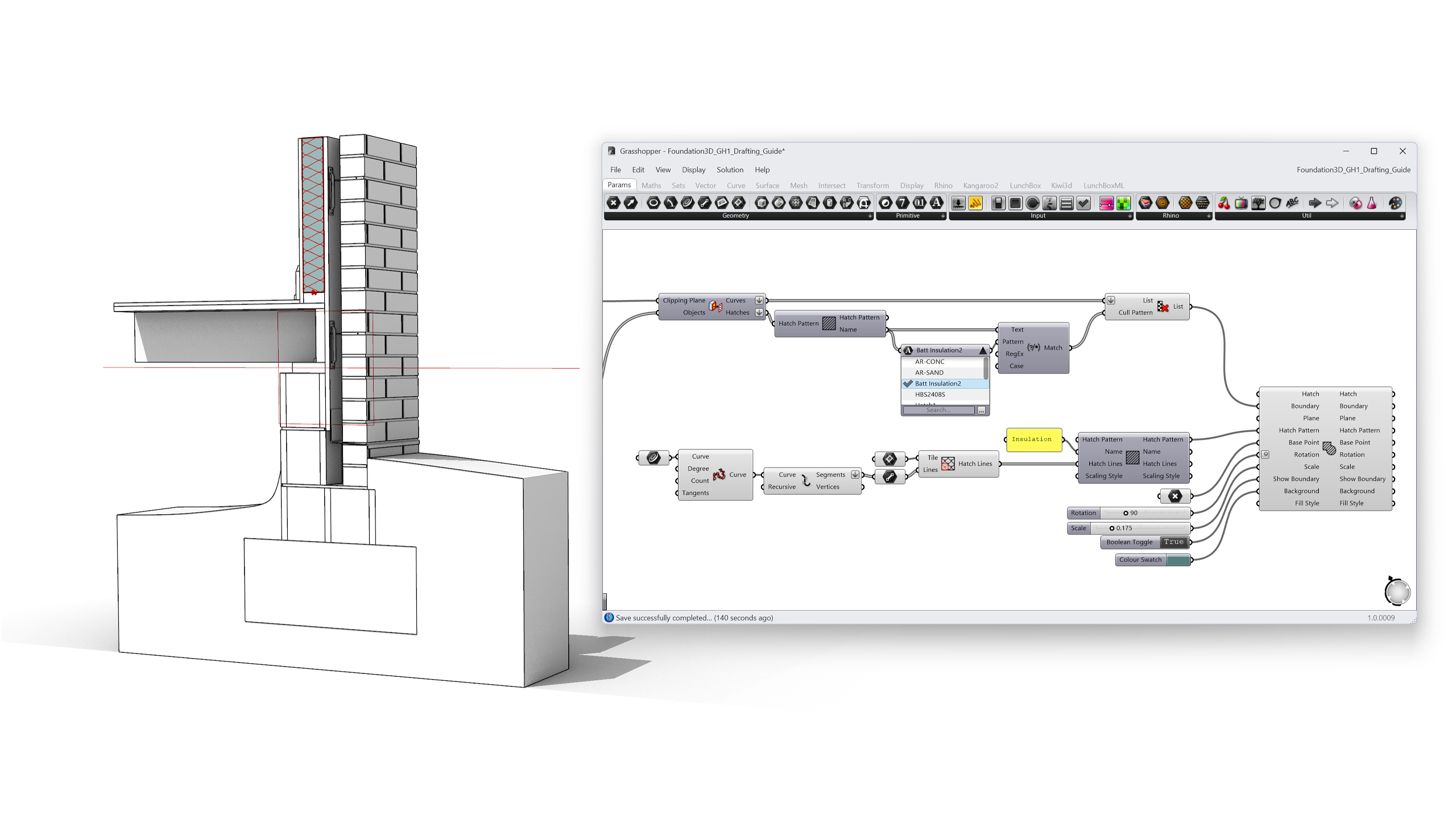
You can then apply the new pattern to the insulation layer in your clipped section, rotating and scaling the tile to match the layer’s orientation and thickness.
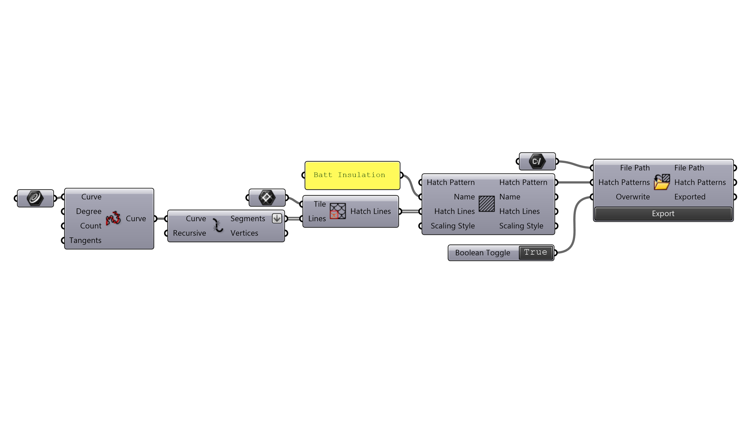
When the pattern is right, save it beyond this file:
- Export Hatch Pattern writes a standard
.patfile (set Overwrite toTruewhen iterating) for use across Rhino and other CAD applications. - Content Cache bakes the pattern into the document so section styles can reference it, which means your parametric section from Chapter 4 can now cut insulation with your pattern.
6. Browsing patterns with the Value Picker
A document quickly accumulates dozens of hatch patterns; Rhino 9 ships with 58 new defaults alone. Scrolling a value list doesn’t scale. The Value Picker (Params tab > Input) is built for exactly this: finding, filtering, and selecting from long lists of values.
Wire a Query Model Hatch Pattern component into the Value Picker. Right-click the query component and choose Add Default Patterns to load Rhino’s whole default library. Expand the picker and:
- Type to search, with Wildcards (
Batt*), Contains, Starts With, Ends With, or full Regular Expressions. - Click to select; Ctrl+Click for multiple values; Space+Click for a series.
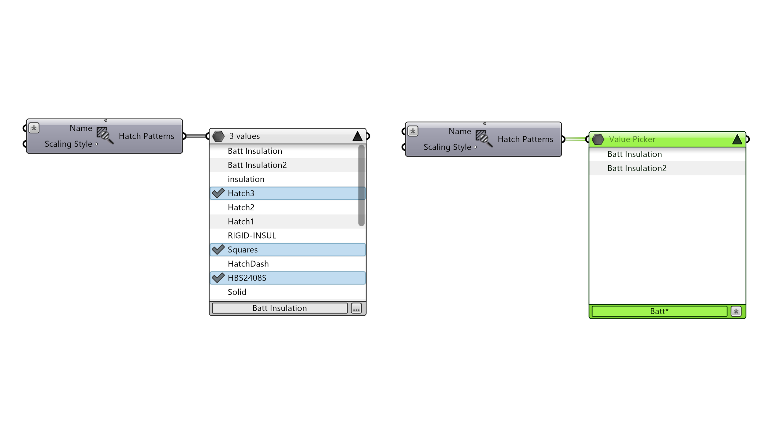
The Value Picker isn’t limited to hatches. It handles numbers, text, and model objects (shown by object name) simultaneously, so the same technique works for picking layers, section styles, or parts from a catalog folder.
7. Inspecting content with the Content Viewer
How do you see a hatch pattern before applying it? Or check what a section style actually contains? Grasshopper previews geometry in the Rhino viewport, but drafting workflows are full of non-geometry data: patterns, linetypes, styles, colors, text.
The Content Viewer (Params tab > Util) displays almost any Grasshopper content graphically, directly on the canvas:
- Connect it to the Value Picker’s output: the selected hatch pattern draws itself in the viewer. Flip through patterns in the picker and preview each one instantly, a live pattern browser in two components.
- Connect it to any component output (curves, BREPs, materials, annotation styles) to isolate and inspect that data without the distraction of everything else previewed in the scene.
- Leave it unconnected and it shows a Rhino viewport embedded in the canvas. Right-click to change the display mode; hold Shift + left mouse to pan, use the mouse wheel to zoom, and the right mouse button to rotate.
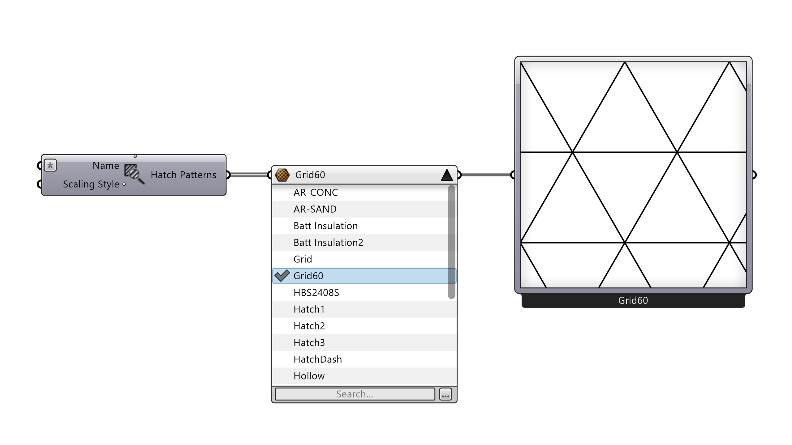
In this workflow the Content Viewer earns its place while designing the hatch pattern in Chapter 5, letting you preview candidates before committing to one.
8. Putting it all together
The complete definition reads like the workflow itself:
- Slider into Model Clipping Plane: one parameter drives the section cut.
- Objects Clipped: context stays whole, the assembly is cut.
- Clipping Drawing Settings into Create Clipped Drawing: a structured 2D detail, extracted on demand.
- Model Hatch Line into Model Hatch Pattern into Export Hatch Pattern: custom material patterns, previewed live and saved as
.pat. - Query Model Hatch Pattern into Value Picker into Content Viewer: find, pick, and verify patterns without leaving the canvas.
- Content Cache: bake the results into the document when they’re ready for layouts.
Change the insulation thickness in the model, drag the section slider, press Update, and the drawing, hatches and layer structure follow. The detail is no longer a drawing you redo; it’s an output you regenerate.
Where to go next
- Drive multiple clipping planes from one definition to generate a full drawing set (plans, sections, details) in one pass.
- Use Grasshopper Player with the exposed Update input to turn this definition into a one-click
MakeDetailcommand for your team. - Explore the Model View component to inspect how a clipping plane projects into a view, useful for debugging drawings with missing geometry.
- Combine with layouts: place the extracted drawing blocks on sheets at scale.
Downloads: GH1-Drafting-Foundation3D.3dm, GH1-Drafting-Foundation3D.gh