In this tutorial, we will learn how to use Gumball to create geometry intuitively and precisely. The Gumball allows us to
![]() Extrude
,
Extrude
,
![]() Wirecut
and
Wirecut
and
![]() Boss
into solid or open geometry, as well as
Boss
into solid or open geometry, as well as
![]() Move
,
Move
,
![]() Copy
,
Copy
,
![]() Rotate
and
Rotate
and
![]() Scale
without running commands.
Scale
without running commands.
Before You Start
If you’re new to Rhino or the
![]() Gumball
, we recommend going through the Gumball: Technical Guide.
Gumball
, we recommend going through the Gumball: Technical Guide.
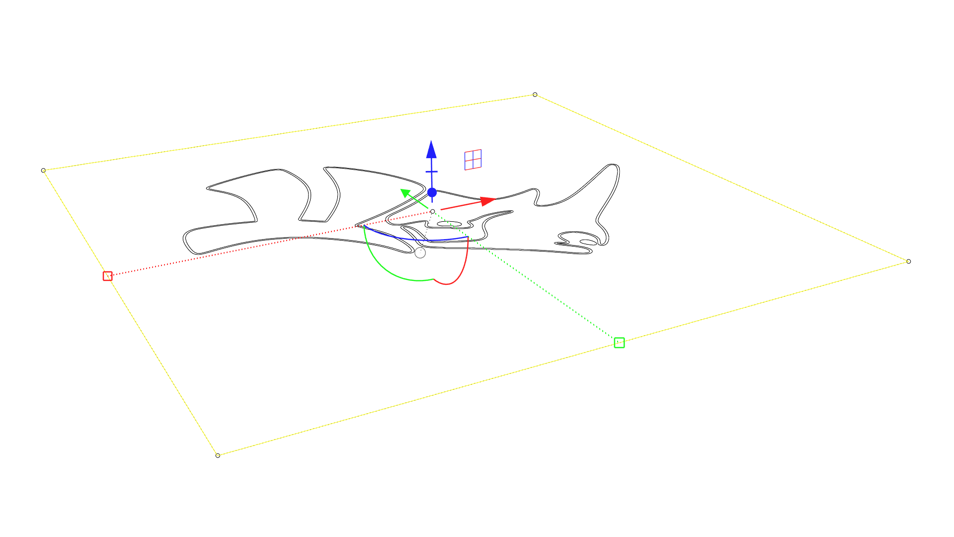
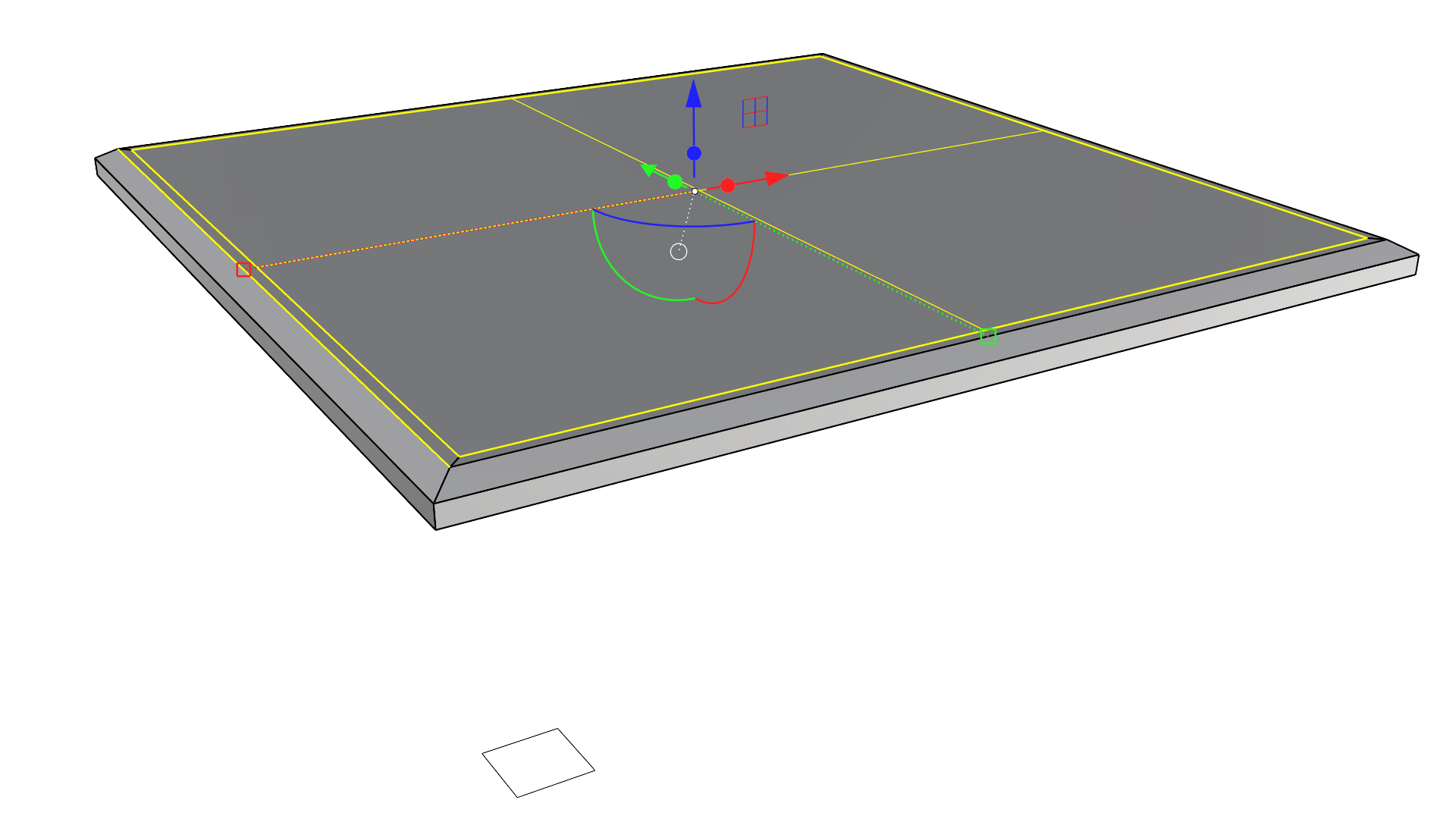
Preparing the Curves
You can create your own set of curves to follow along or download the Gumball_Coffee_Table.3dm used in this tutorial.
In this part, we will duplicate the simple set of starting curves. These copies will help us create the details of our table (chamfers, glass frame, legs, etc.). We will also learn how to move the geometry to the correct location in space. For this, we will use
![]() Gumball
scale and move capabilities as well as learn how to
Gumball
scale and move capabilities as well as learn how to
![]() GumballRelocate
on the object itself. Let’s get started…
GumballRelocate
on the object itself. Let’s get started…
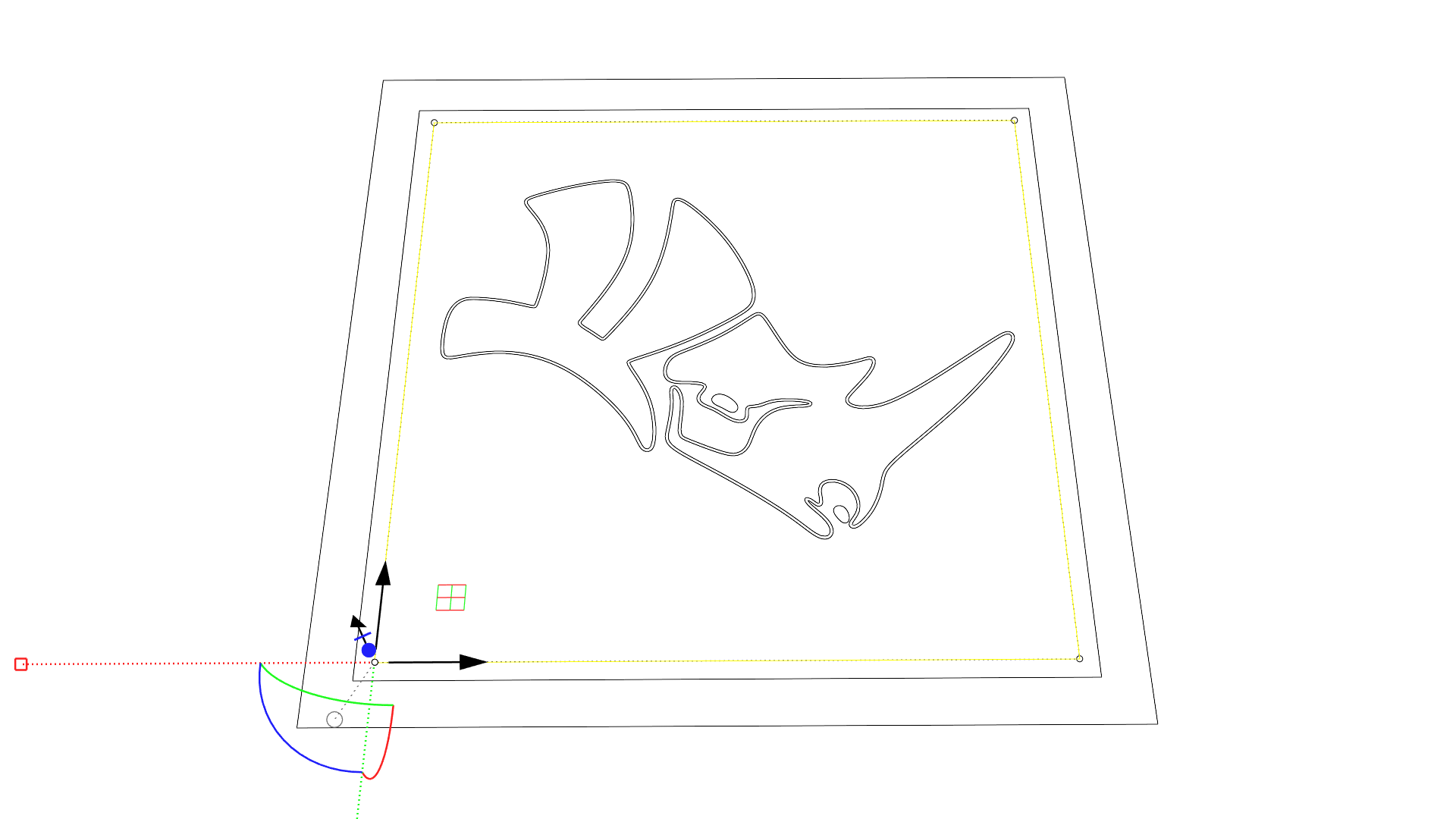
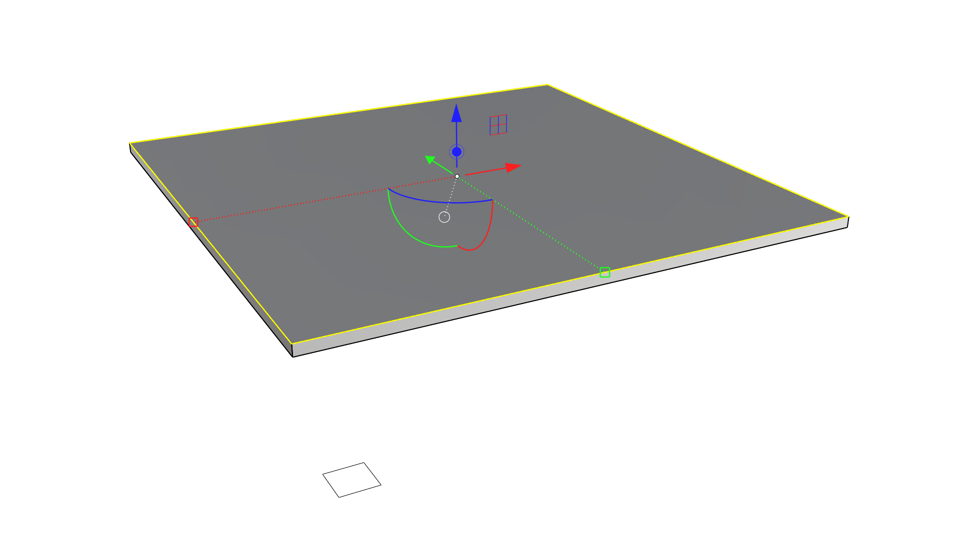
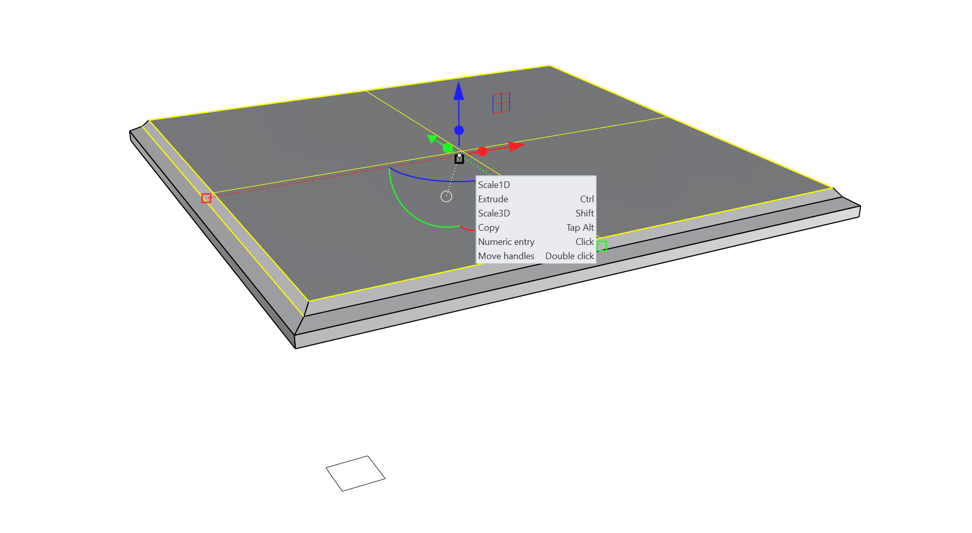
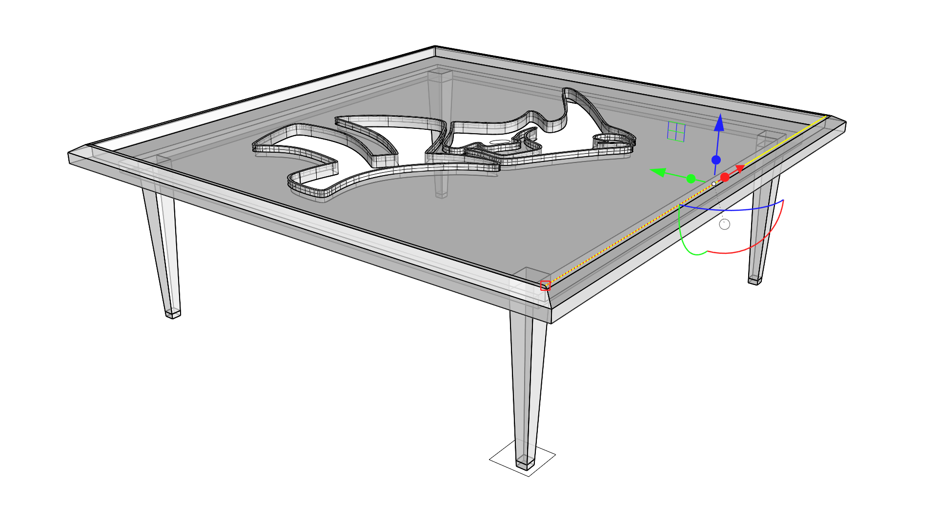
- Select the square polycurve and enable the
 Gumball
from the bottom of the Rhino interface.
Gumball
from the bottom of the Rhino interface.
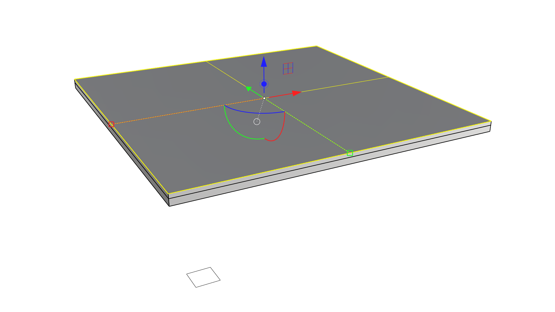
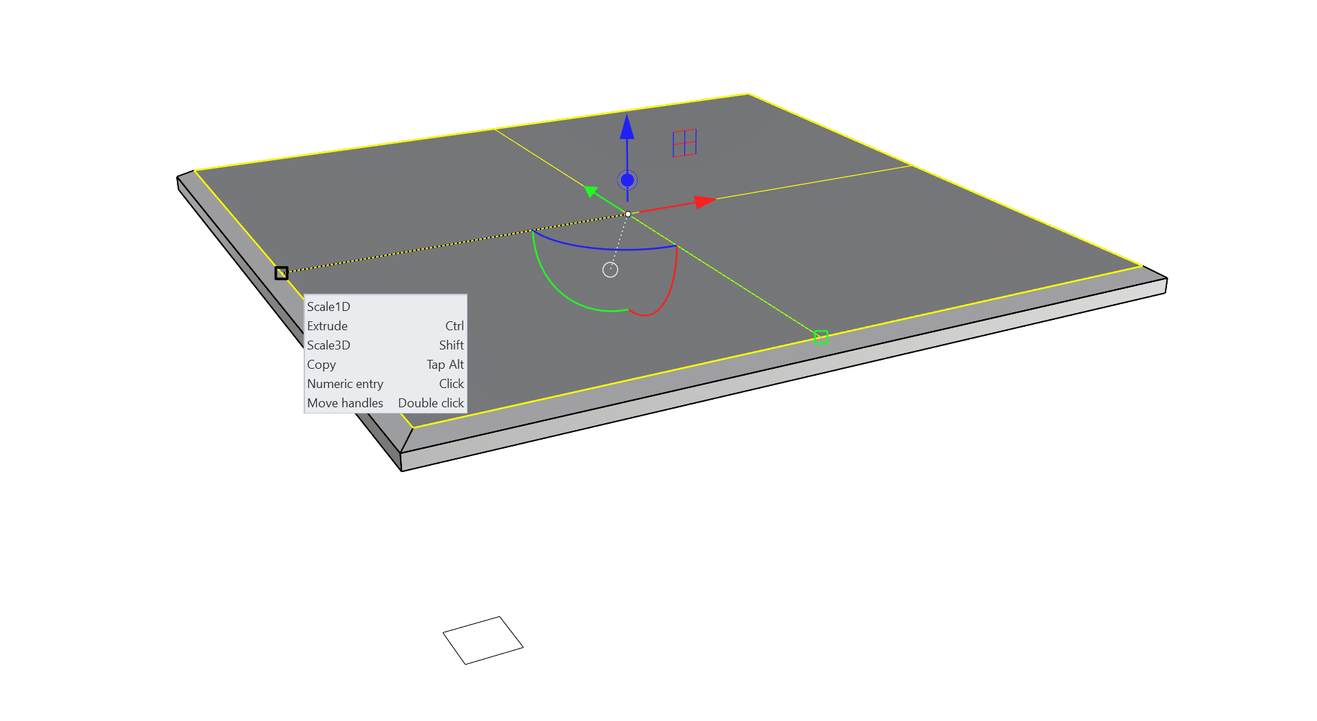
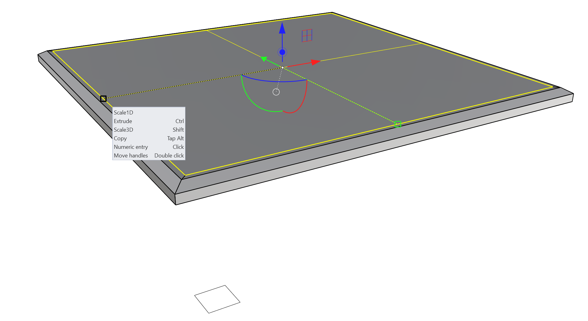
- Using the 2 axis XY plane handle, click and drag while holding the key to scale the square inward. Tap the key to make a copy.
- Repeat Step 2, making another copy of the square inset slightly from the first.
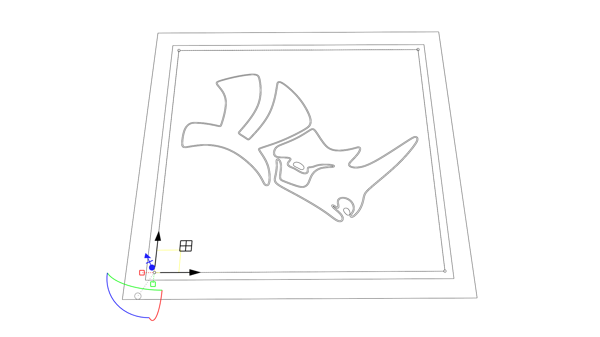
- Double-click and drag the origin of the
Gumball
for the inner square to relocate it to an Osnap at its corner.
- Use the
Gumball
at the new location to Scale 2D again making another copy that will represent the top profile of the table leg.
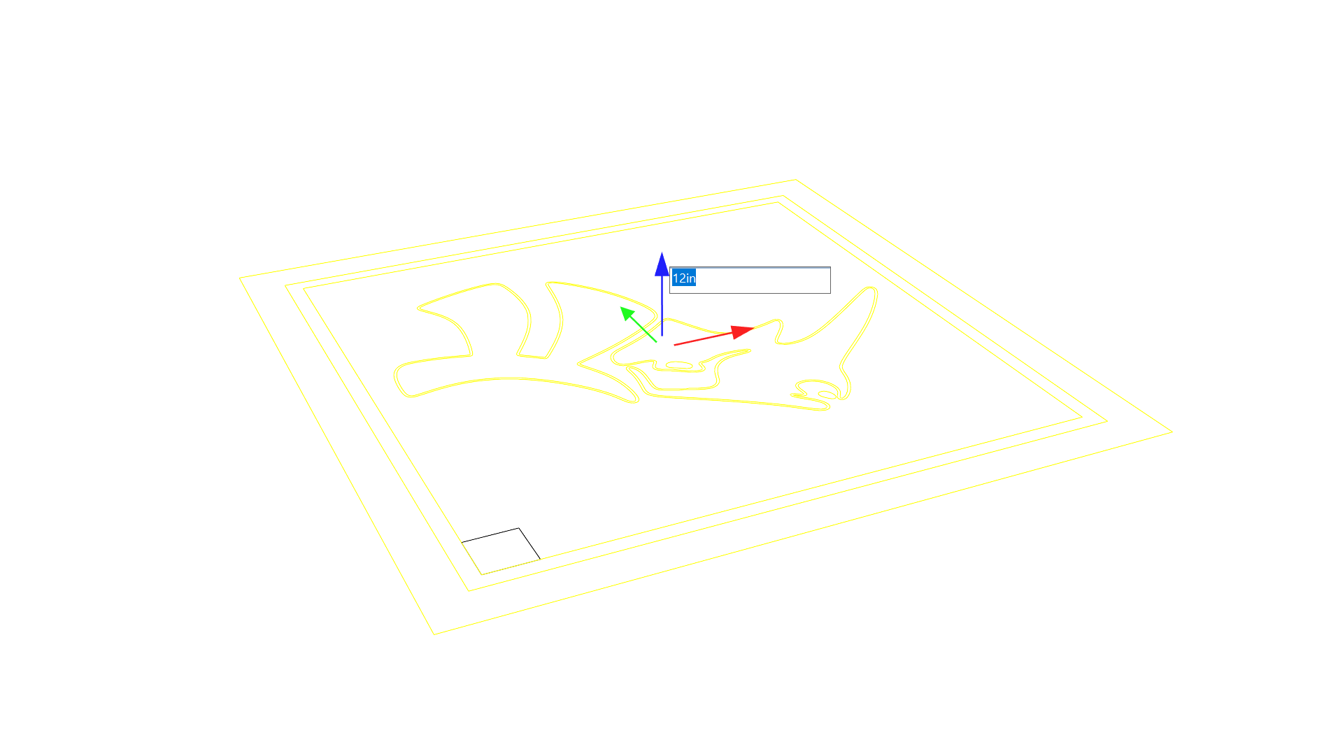
- Select all the other curves but the last copy and click and release on the Z axis Move handle on the
Gumball
. Enter 12in and press
to move those curves 12 inches in Z despite the model being set to use Centimeters.
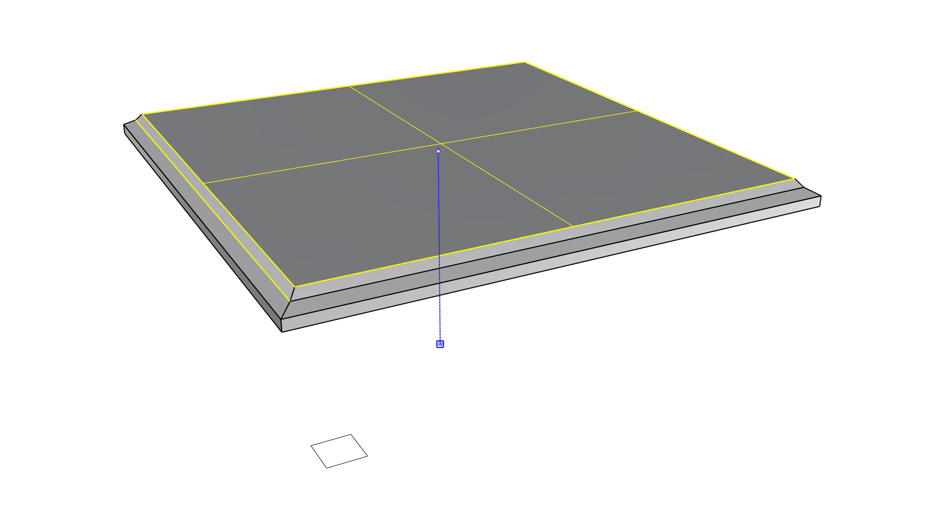
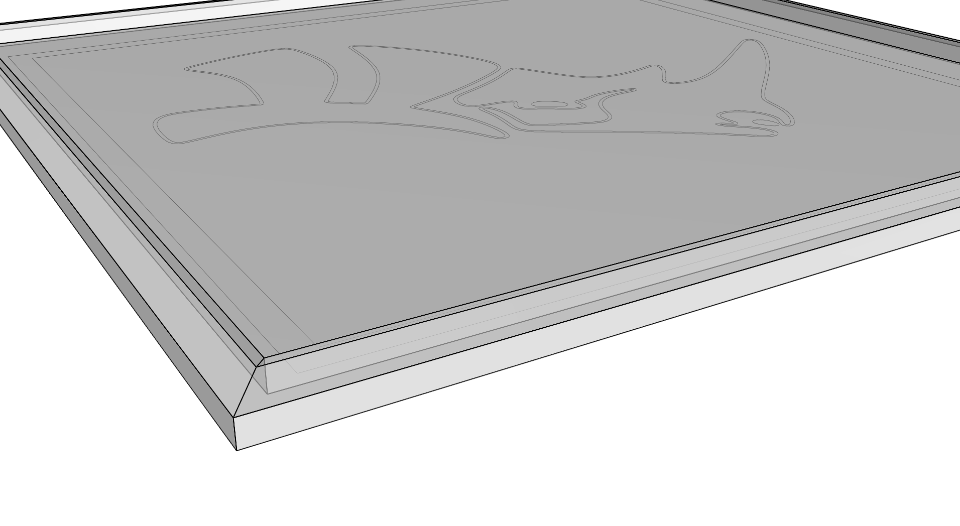
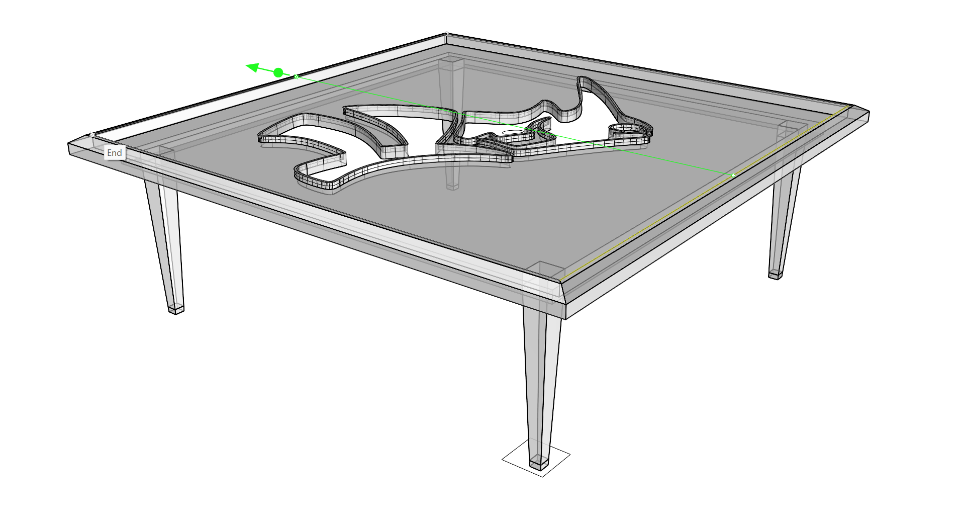
Creating the Tabletop
With the curves created and in place, we will use the Gumball’s extrude capability to obtain the main volume of our tabletop. We will also create the chamfer and the glass frame by using a cool trick with the scale handle.
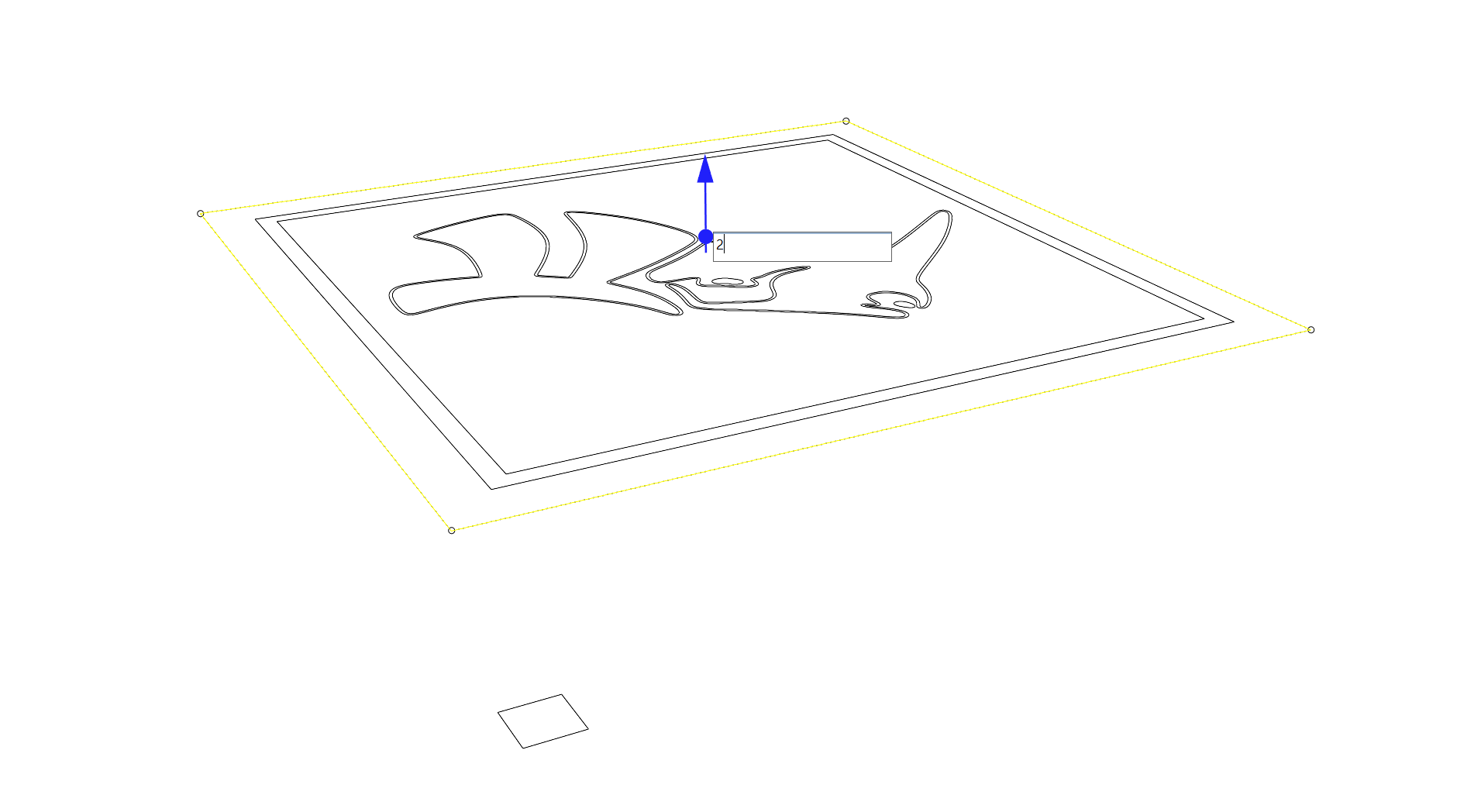
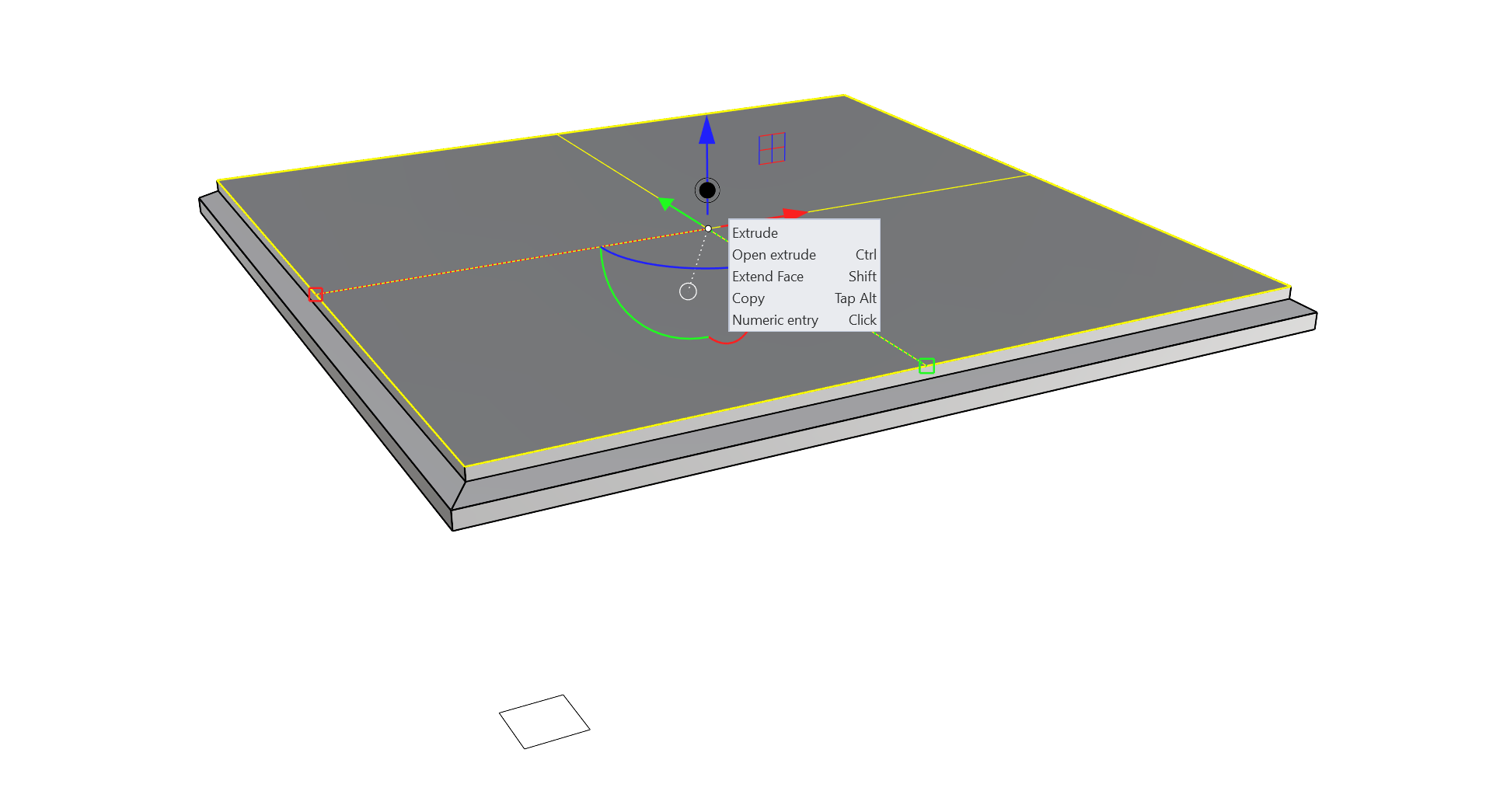
- Select the outer square and click and release on the Z axis Extrude handle on the
Gumball
. Enter 2 and press
to make a solid extrusion from the square in centimeters. Set the viewport to Shaded mode to see the extrusion shaded.
- Using the + keyboard combination, click the top face on the extrusion made. This is known as sub-object selection.
- Using the Extrude handle in the Z axis on the
Gumball
, create another extrusion. This can be by eye and does not require a numeric value.
- Sub-object select the top face of the polysurface created and click and drag on a 1D scale handle while holding to scale it in 3D.
- Using the Z axis Extrude handle, extrude up the top face via a sub-object selection again. This can also be done by eye.
- Repeat Step 10, scaling the new top face inward uniformly.

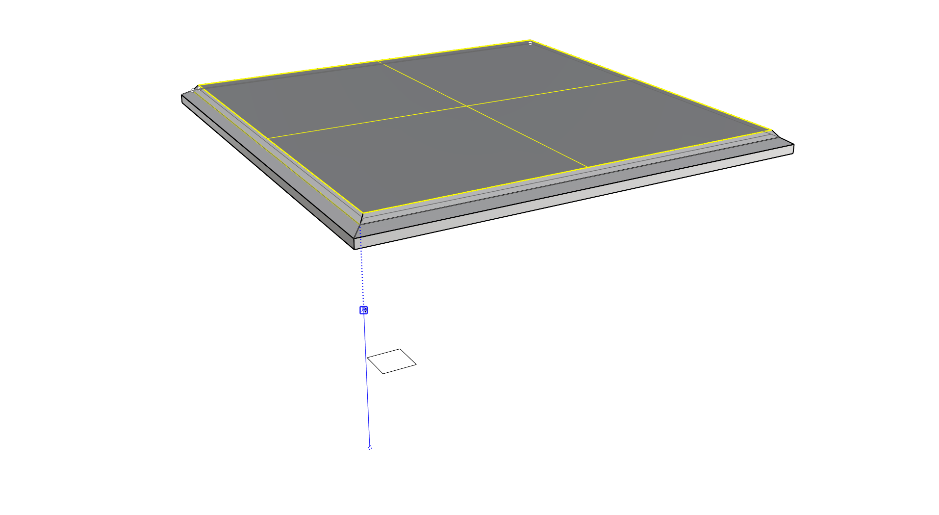
- Using the + keyboard combination sub-object, select both the top face and one of the adjacent edges of the polysurface.
- Double-click the Z axis 1D scale handle on the
Gumball
to relocate it out of the way. This will make the next step easier.
- Double click the
Gumball
origin and relocate it to an End Osnap at the end of the polysurface edge you sub-object selected.
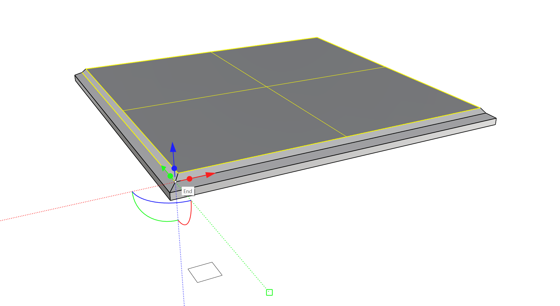
- Using the Z axis 1D scale handle on the
Gumball
, click and drag until the scale handle snaps to the origin of the Gumball’s current location.
- The two sub-objects that were selected are now coplanar in that location.
- Sub-object select the center face and, using the 1D scale handle, click and drag with to scale in 3D to adjust the size by eye. Note that scaling a flat object in 3D is the same as scaling it in 2D. If you prefer, you can use the 2 axis handle with Shift to perform this scale instead.
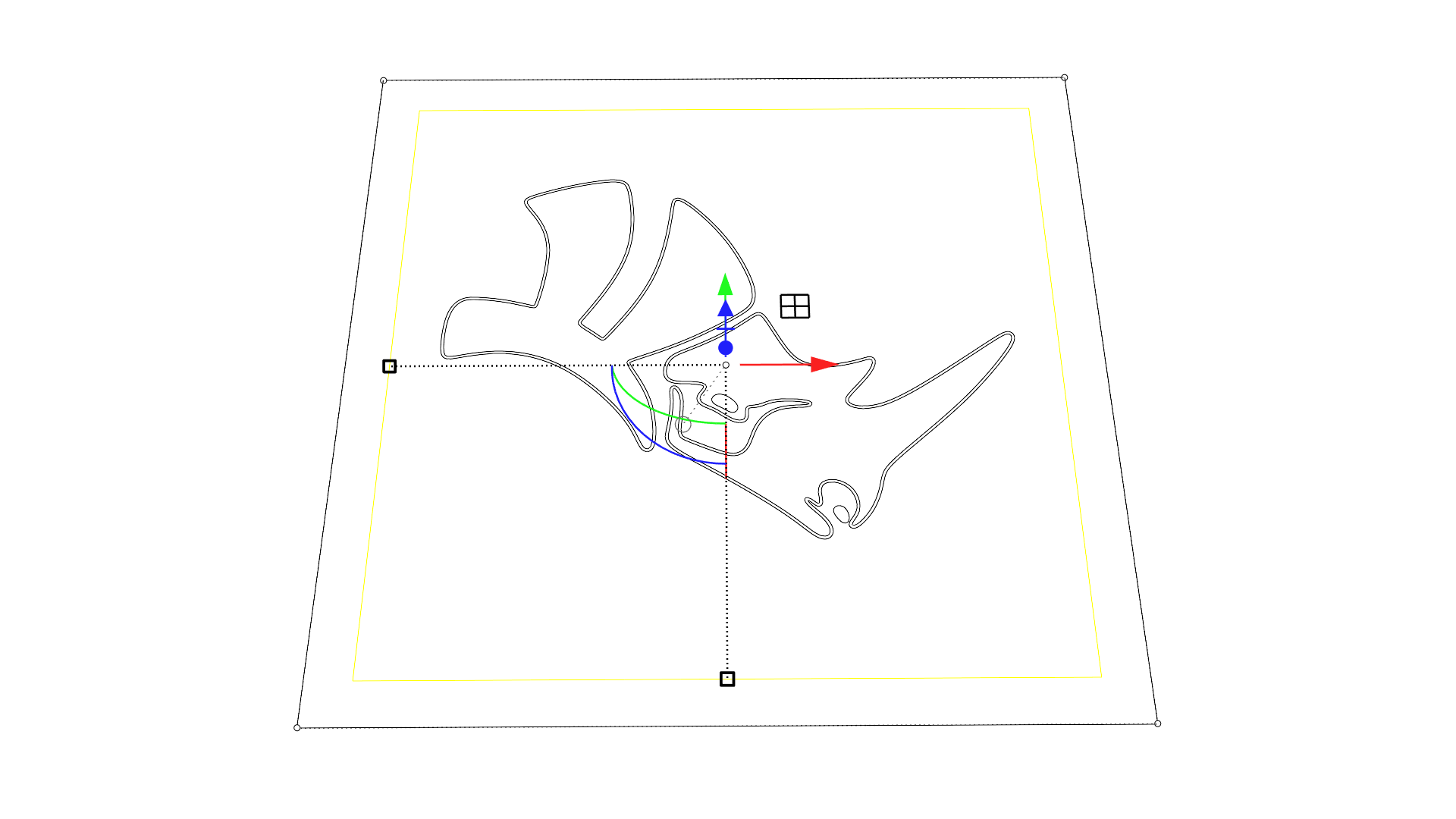
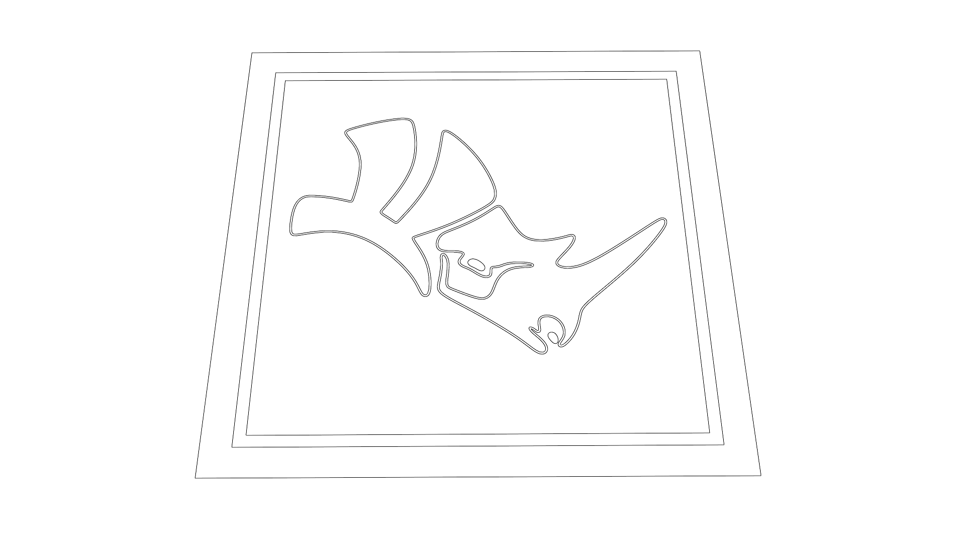
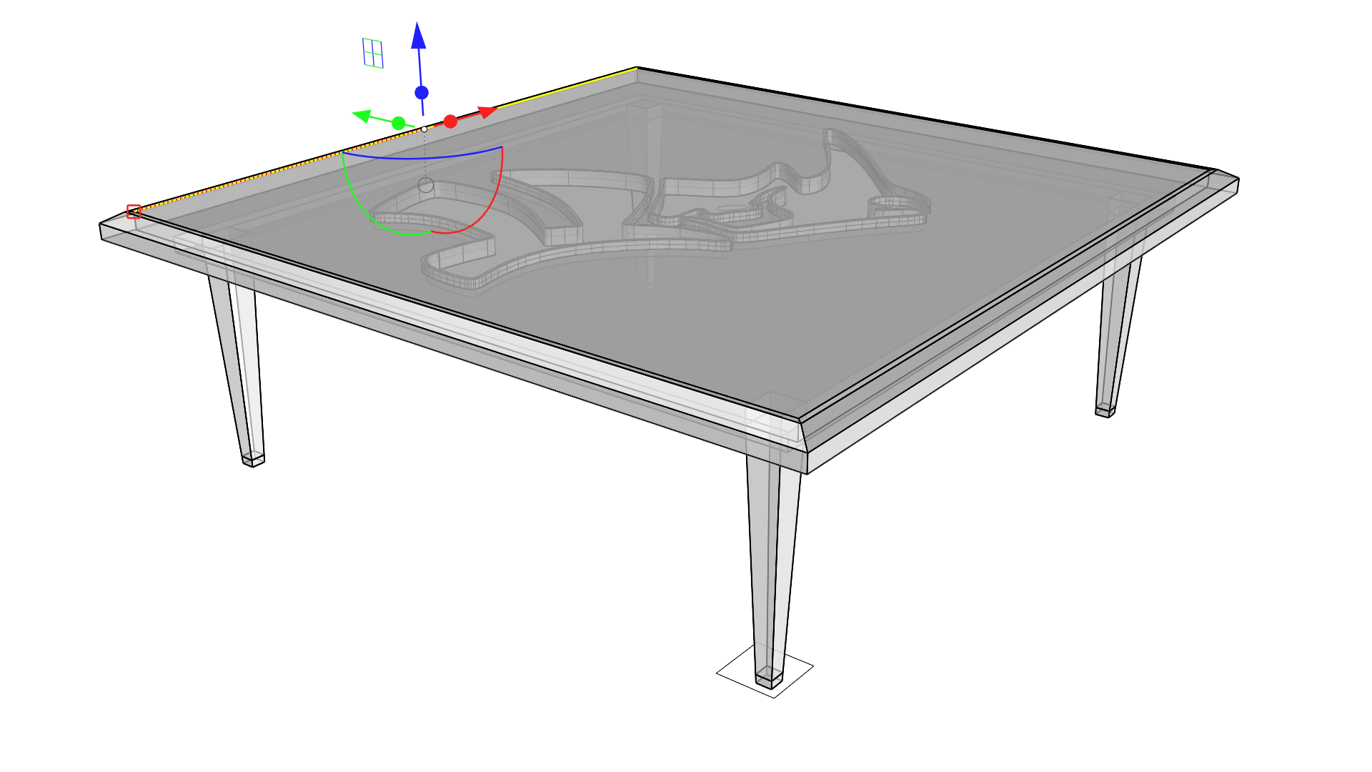
Detailing: Frame and Emboss
We are ready to create the actual glass pocket! We will then focus on using the Rhino logo curves to create a boss and an opening in the tabletop with the shape of the logo. To this end, we will mainly be using the Extrude and Cut handle of the
![]() Gumball
.
Gumball
.
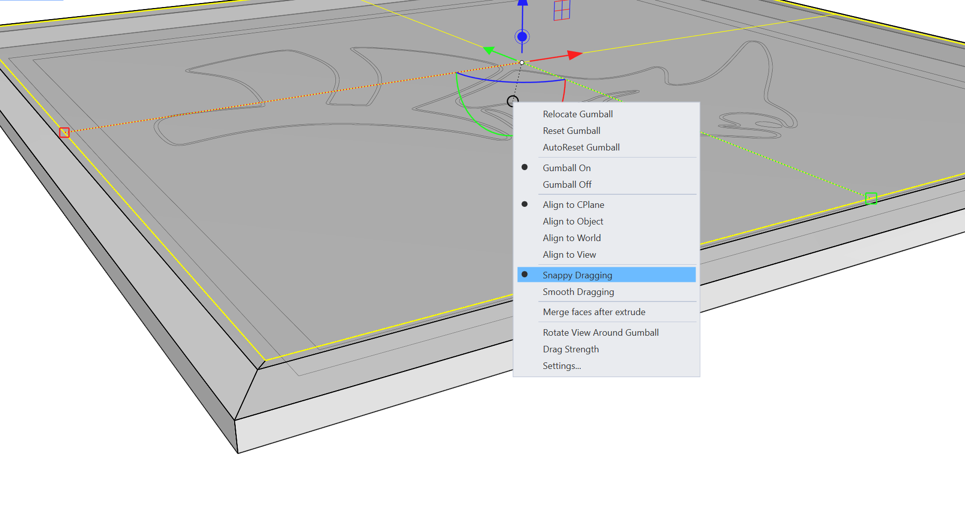
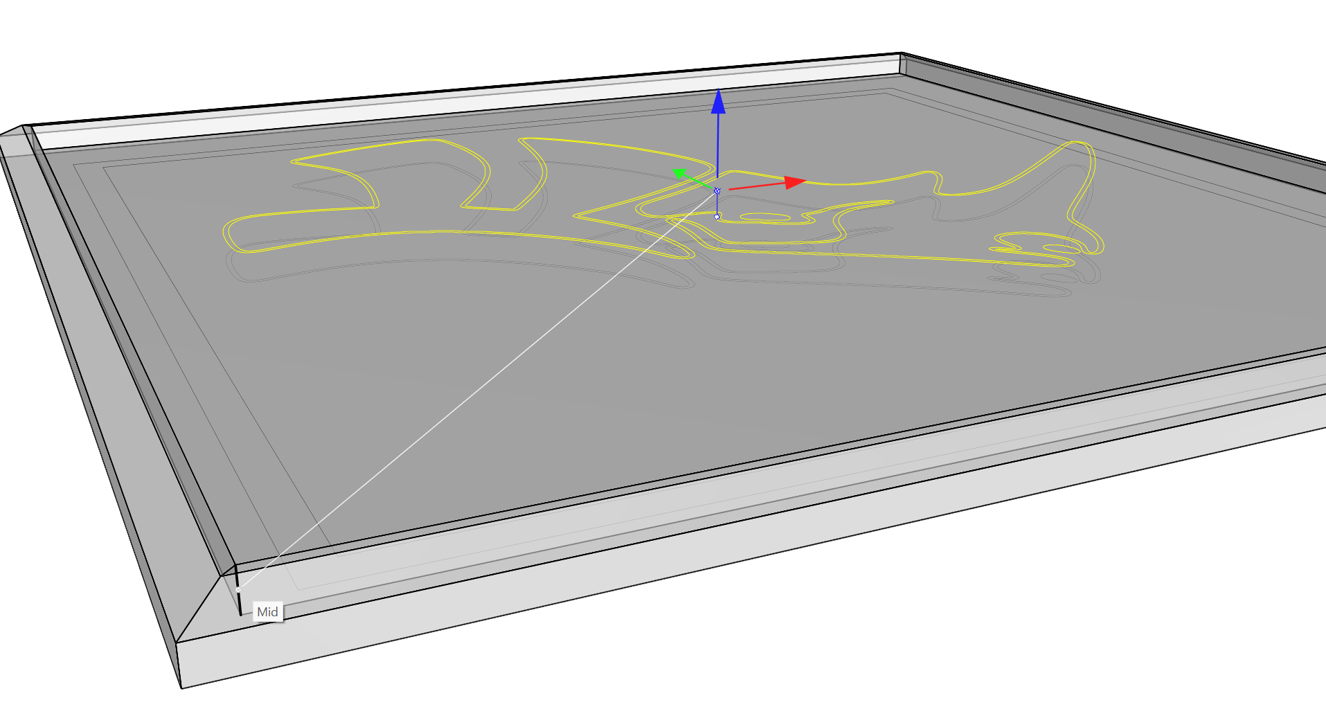
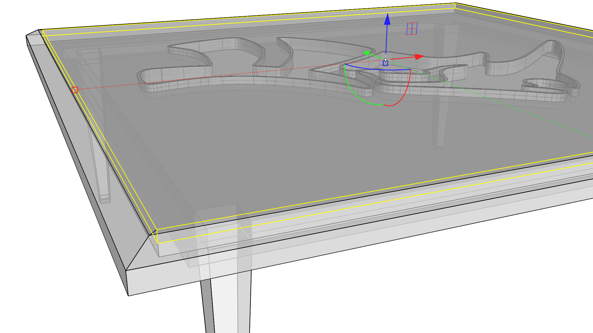
- Switch the viewport to Ghosted mode to make the following steps easier and sub-object select the top center face of the polysurface. Click the settings circle handle on the
Gumball
and set it to Snappy Dragging. This will allow us to snap to Osnaps when extruding, moving, or cutting.
- Click and drag on the Z axis Extrude handle and snap to a Midpoint Osnap along the outer corner edge of the polysurface.
- This will make a pocket for the glass top of the table.
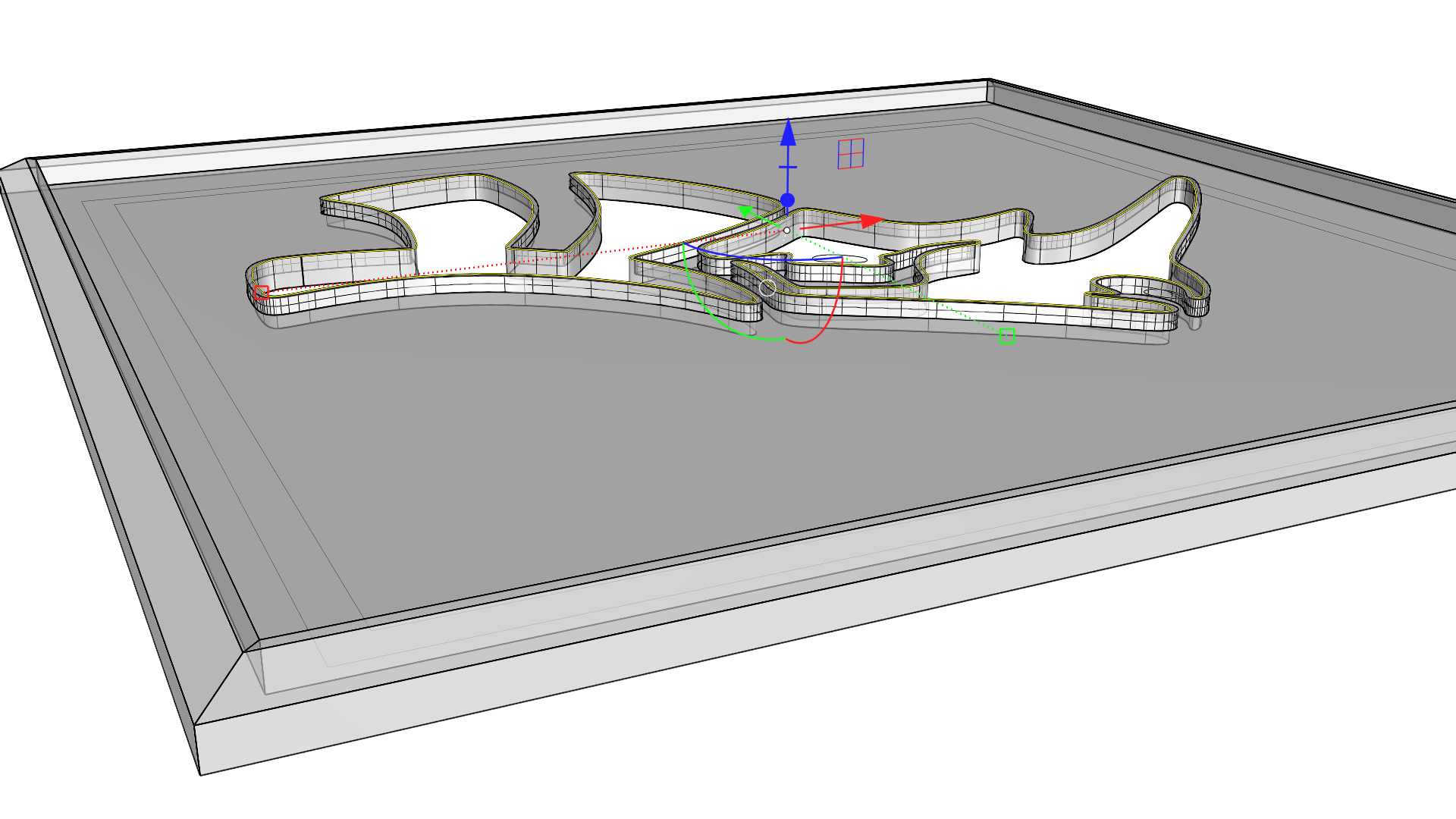
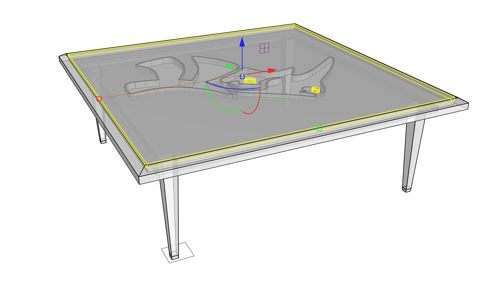
- Select the Rhino logo curves and using the Z axis Move handle move them up and then mouse over the Midpoint Osnap on one of the vertical edges in the pocket just created to snap to that location.
- With the outer Rhino logo curves selected, use the Z axis Cut handle on the
Gumball
, drag down while holding
and release at any Osnap along the bottom of the pocket.
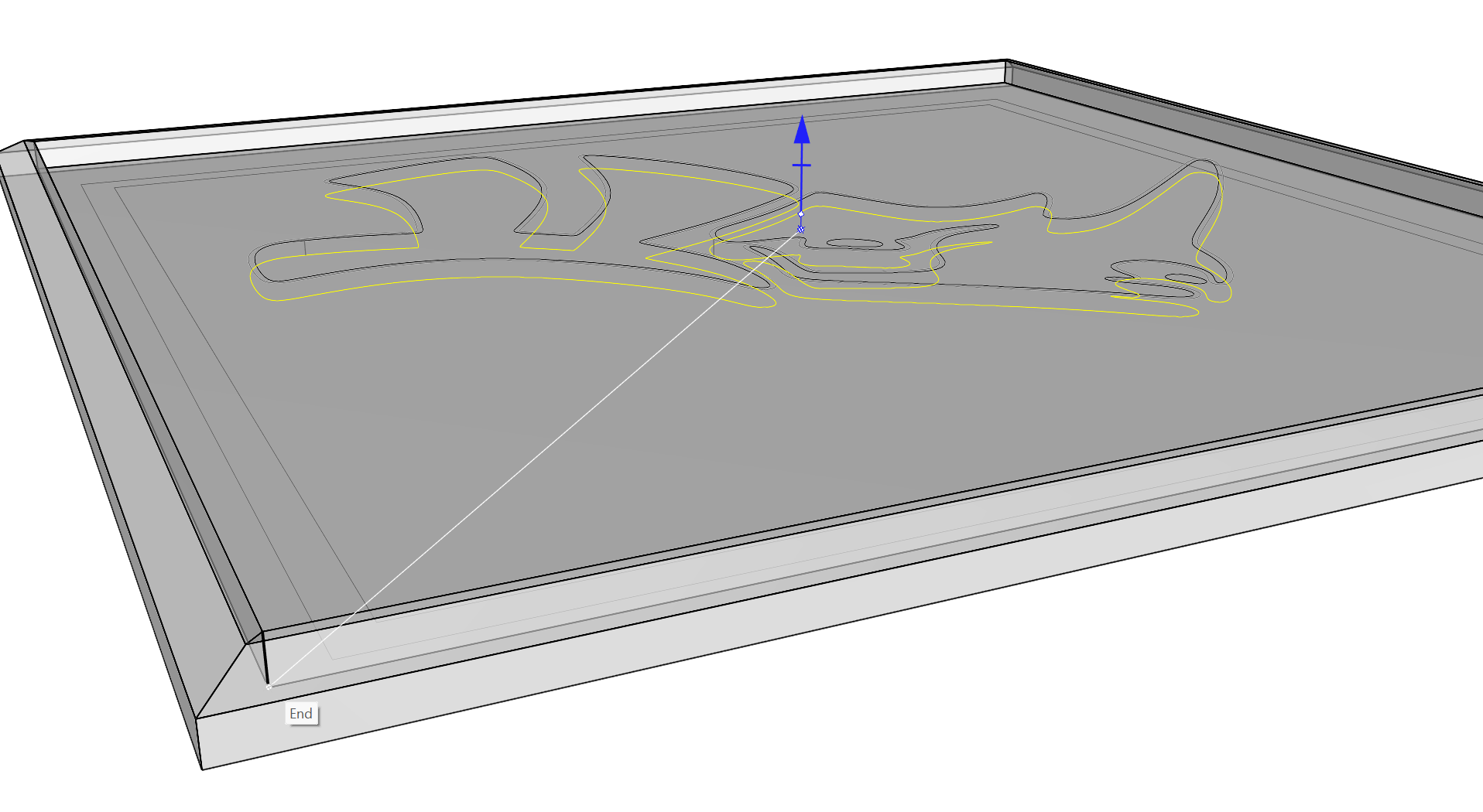
- This will create a Boss that is part of the polysurface.
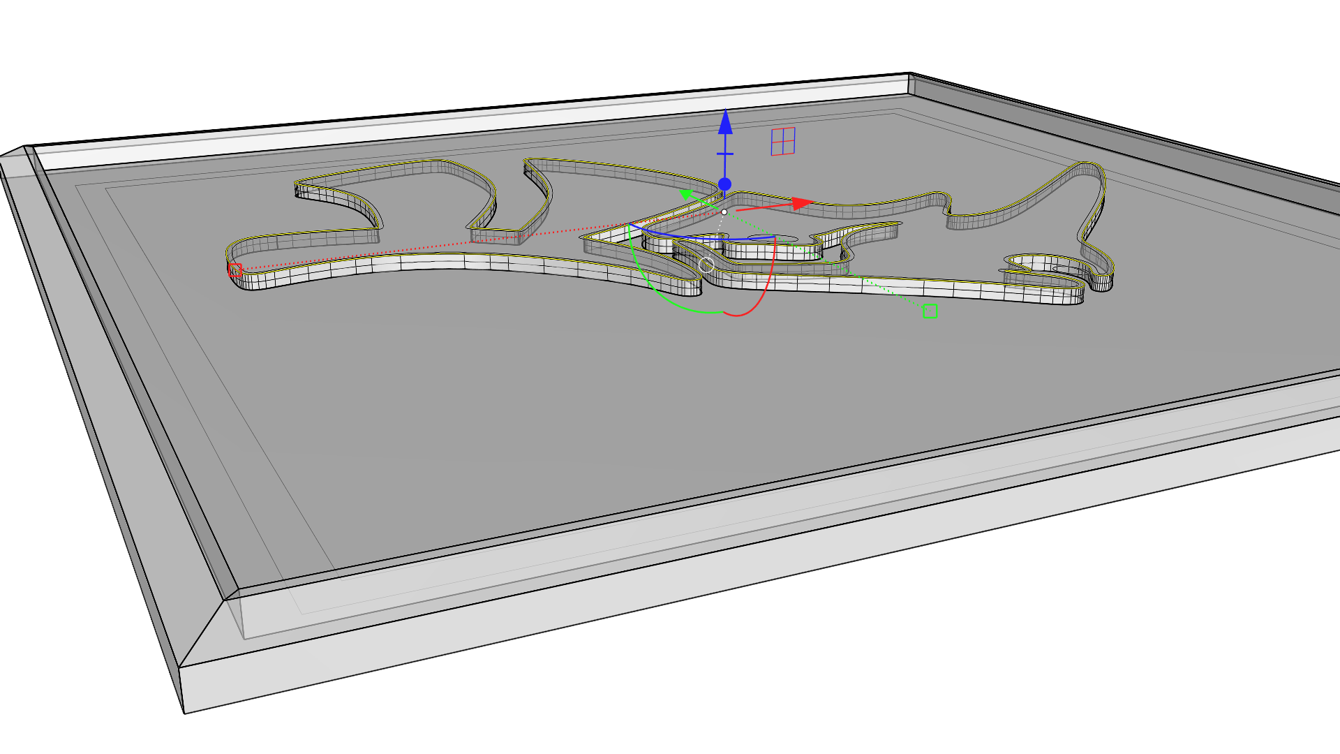
- With the inner Rhino logo curves selected, drag down on the Z axis Cut handle and release once through the polysurface.
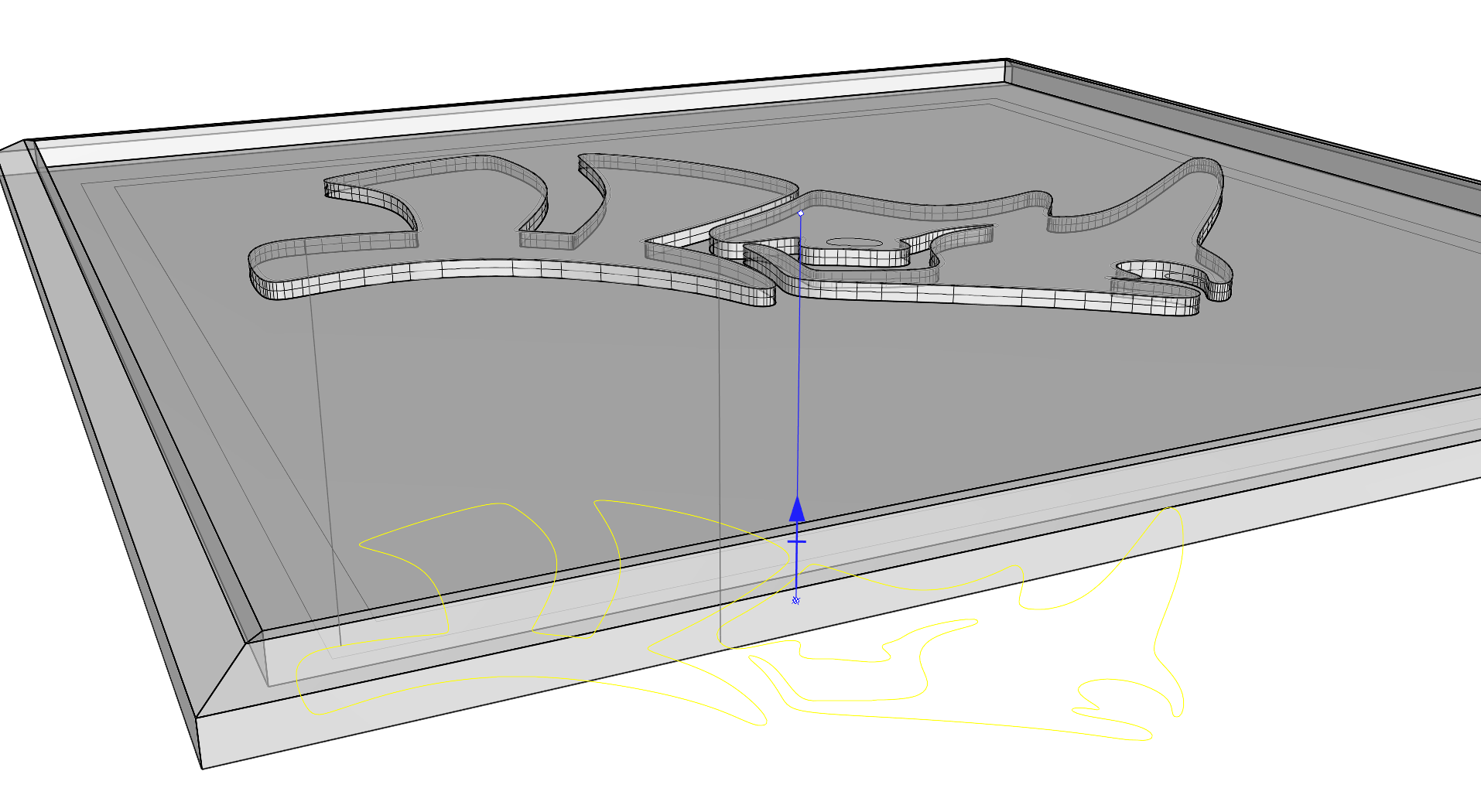
- This will Cut through the polysurface, leaving a Rhino logo-shaped hole inset slightly in the Boss.
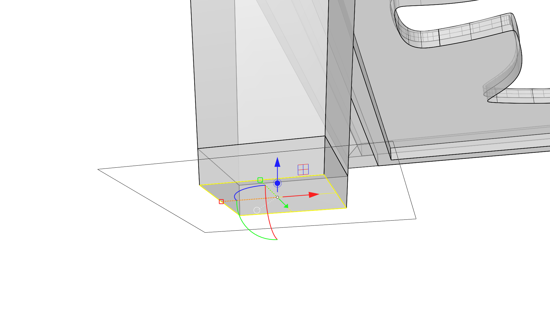
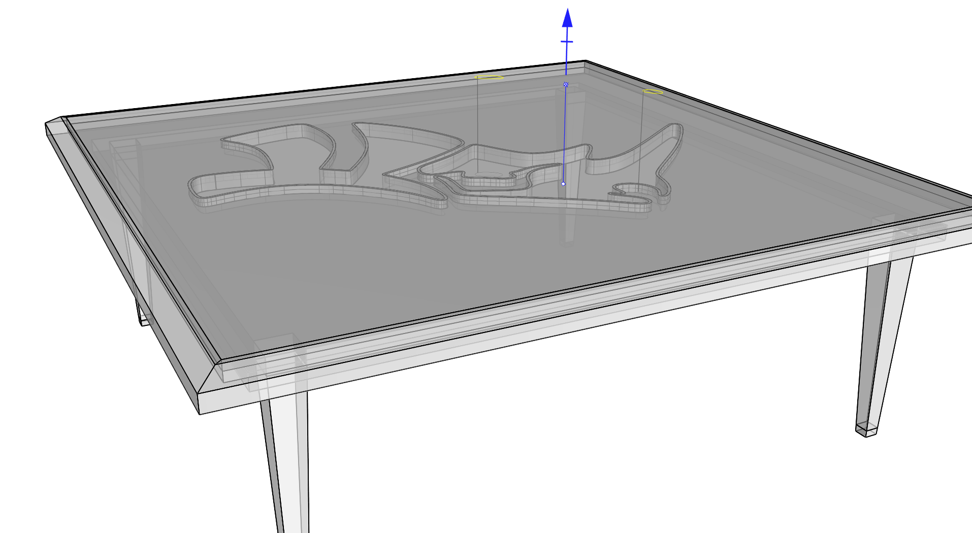
Adding the Legs
Let’s concentrate on creating the tapered legs and copying them on all four sides. Essentially using the Extrude, Scale and Relocate options. We will also see how to use Rotate and Copy through the
![]() Gumball
to duplicate the legs on all corners.
Gumball
to duplicate the legs on all corners.
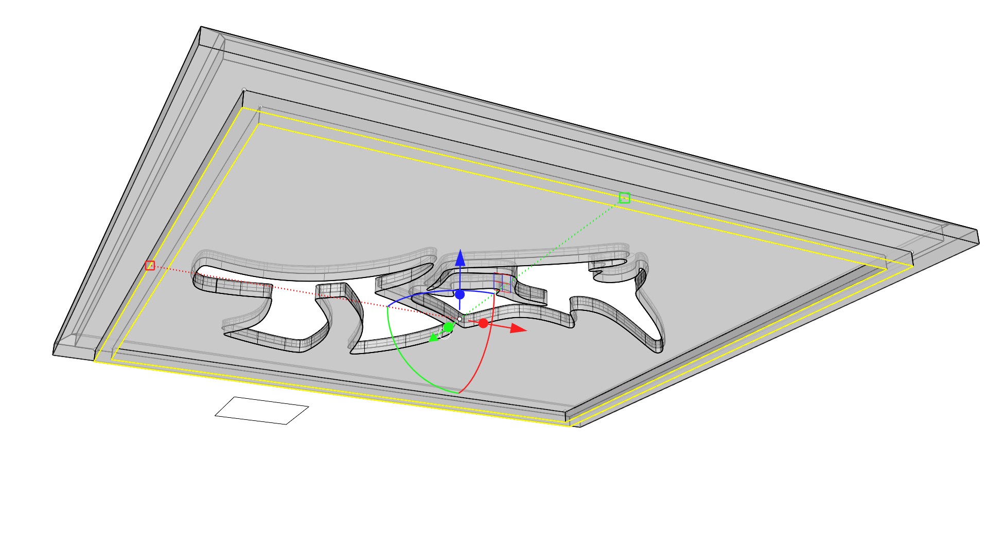
- Viewing the model from underneath, select the two inner square curves and click and release on the Z axis Extrude handle. Type -2 and press .
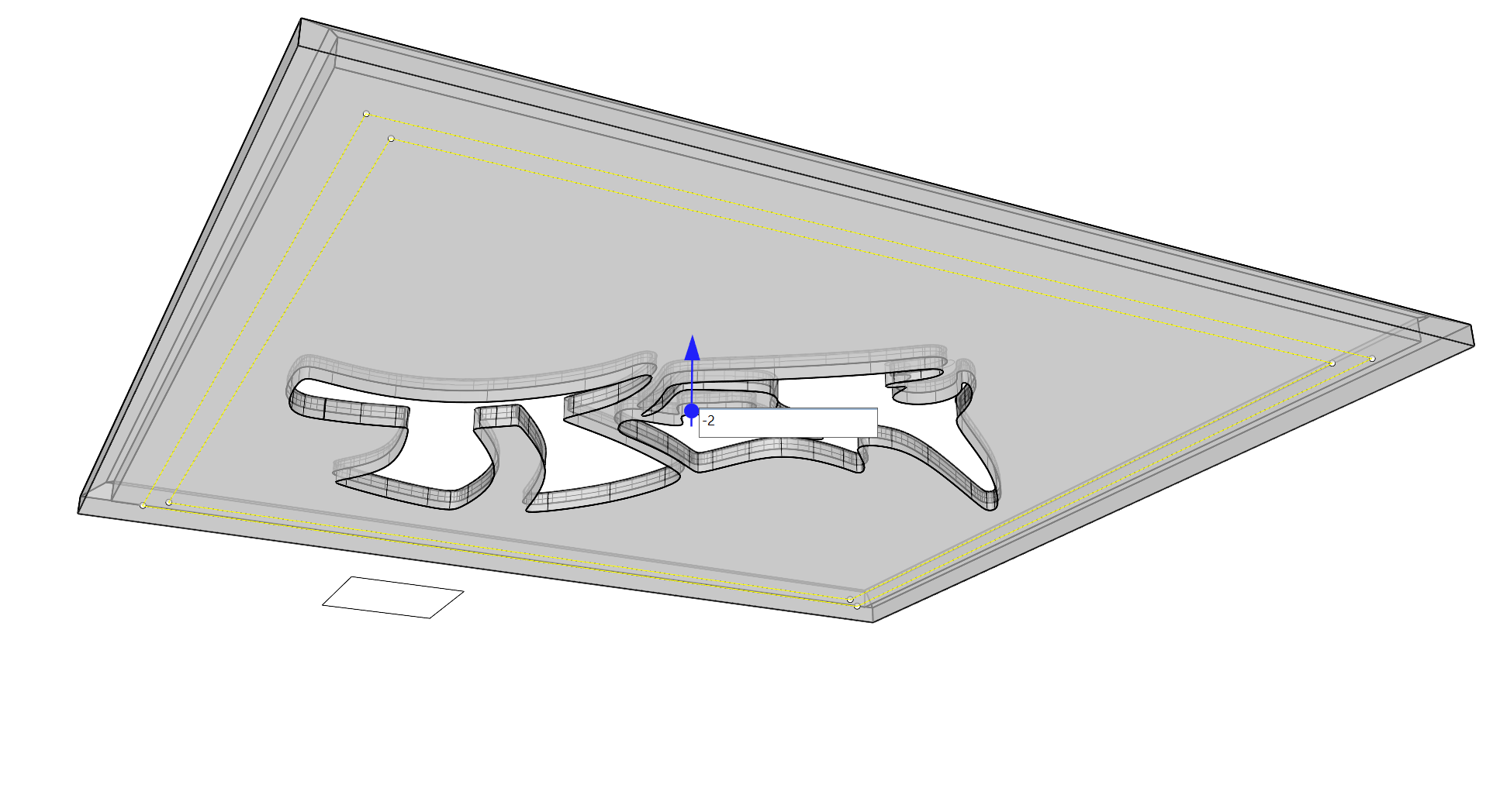
- This will create an extrusion in the opposite direction that the Z axis arrow points on the
Gumball
. This form will brace the legs that will be modeled next.
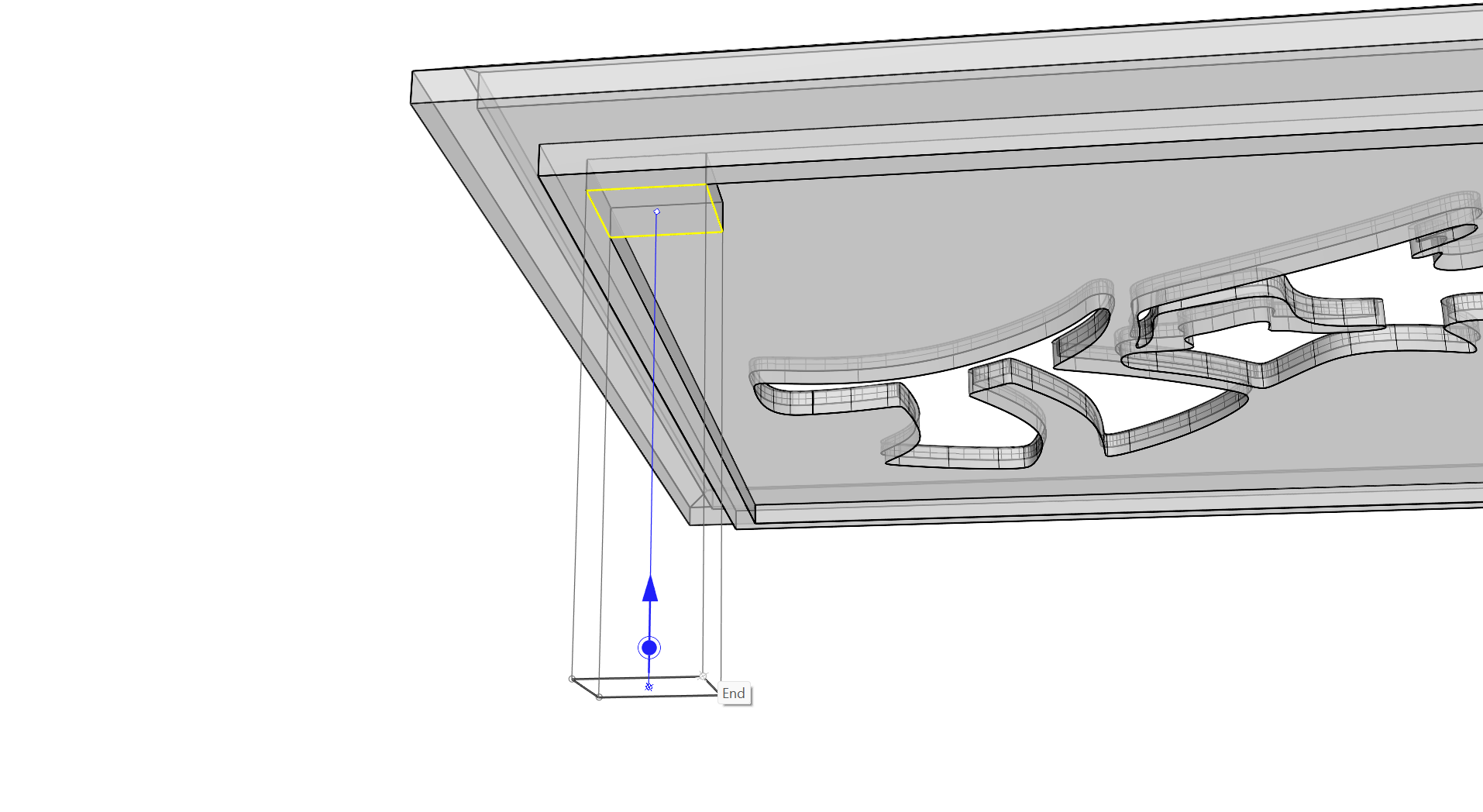
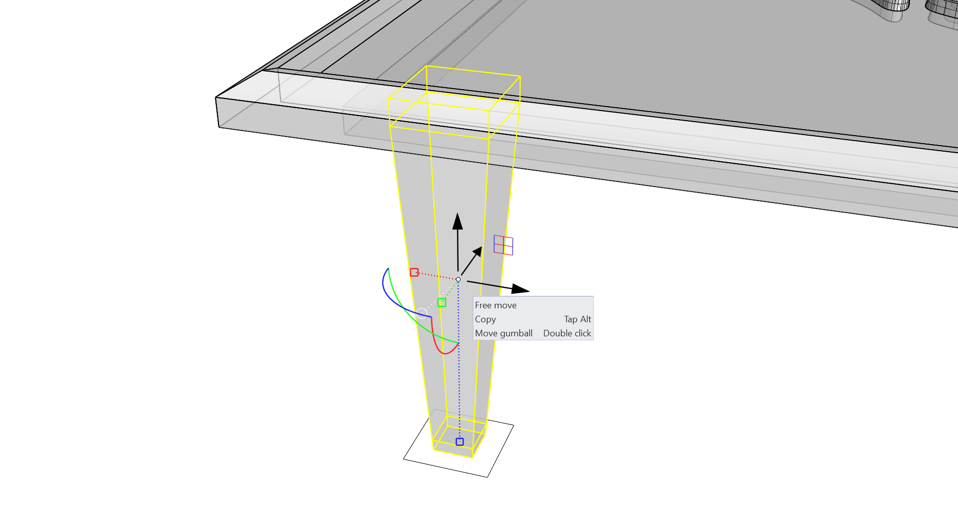
- Select the small square made previously for the table legs and click and drag on the Z axis Extrude handle snapping to an End Osnap at the top of the brace form just made.
- Using + to sub-object, select the leg extrusion’s bottom face.
- Click and drag on the Z axis Move handle and snap to an End Osnap at the bottom of the brace form.
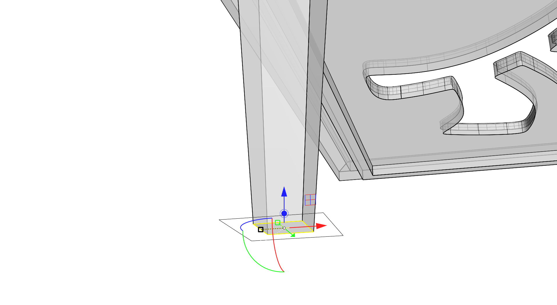
- Sub-object select the bottom face of the extrusion again in its new location.
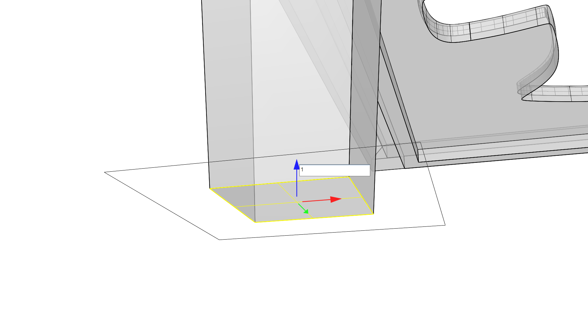
- Using the Z axis Extrude handle, extrude this face downward ending on any Osnap on the original small square curve.
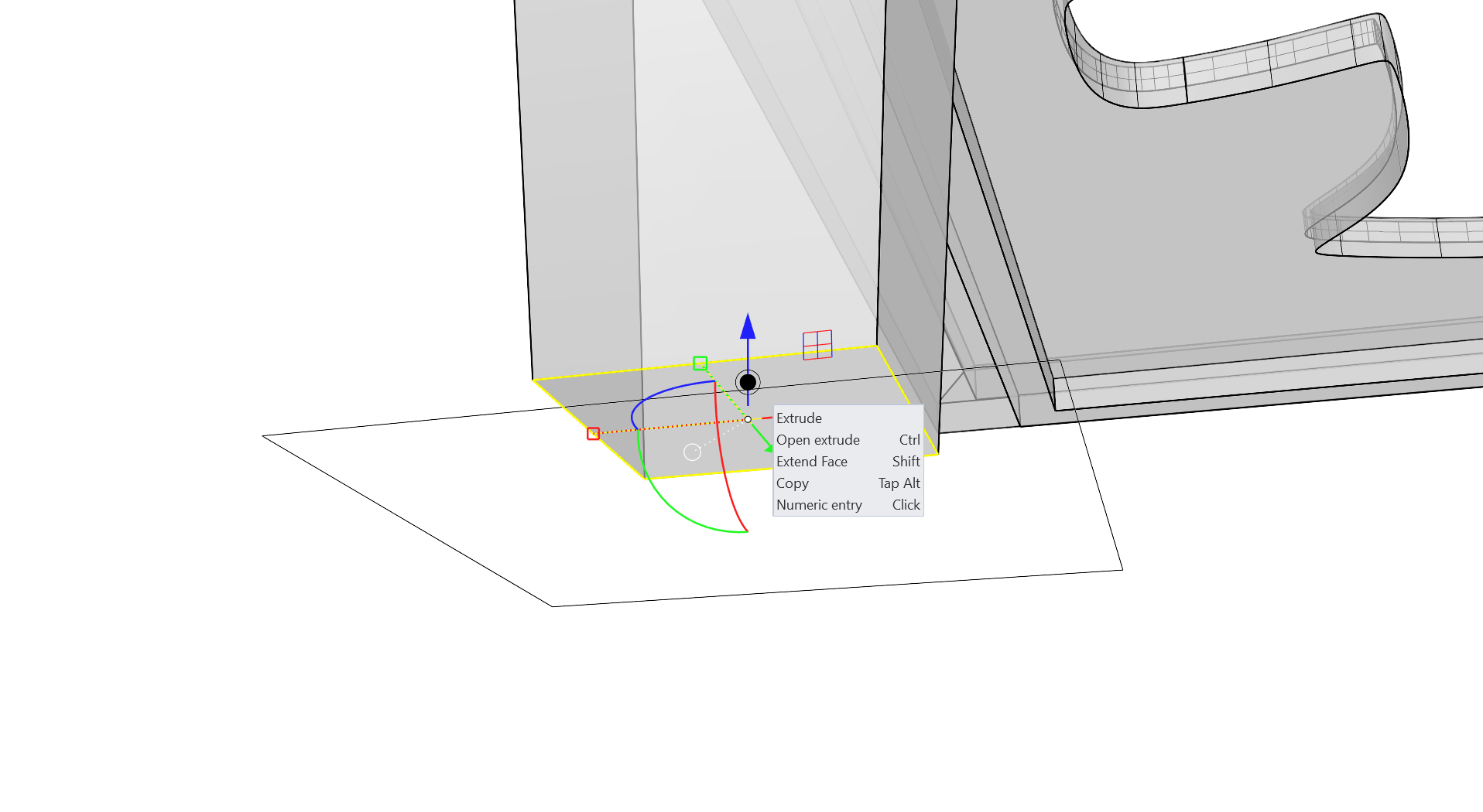
- Sub-object select the bottom face of the polysurface and use the Z axis 1D scale handle with held to scale uniformly inward. You can do this by eye to add a taper to the leg form.
- Sub-object select the bottom face of the polysurface again then click and release on the Z axis Move handle on the
Gumball
entering a value of 1 before pressing
. This will provide a 1-centimeter space to model the foot of the leg.
- Sub-object select the bottom face and, using the Z axis Extrude handle, click and drag it down while holding to Extend. Tap to make a copy and release the drag at any Osnap on the original small square curve.
- This creates a separate polysurface extended with the same leg taper that we defined when scaling.
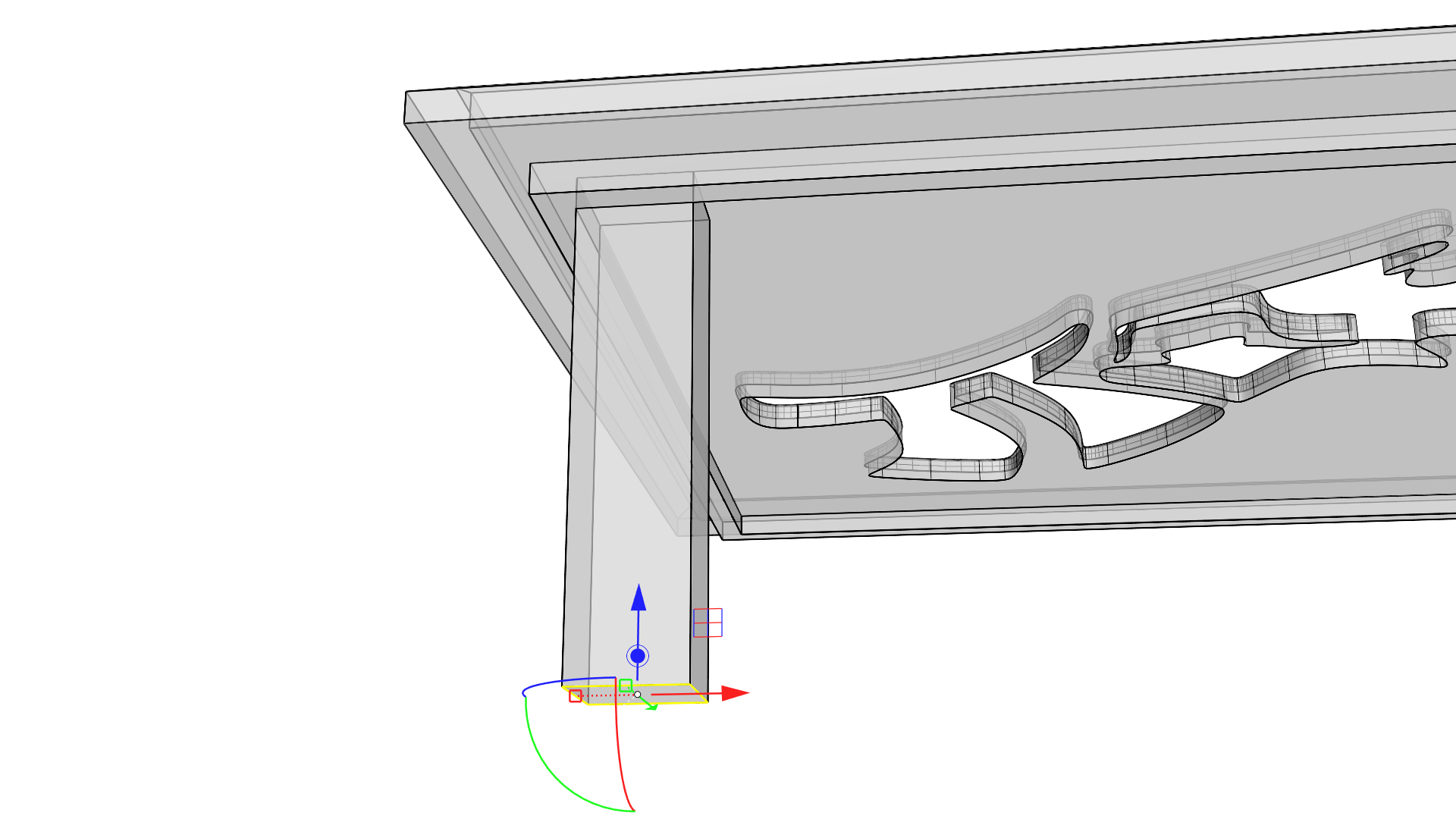
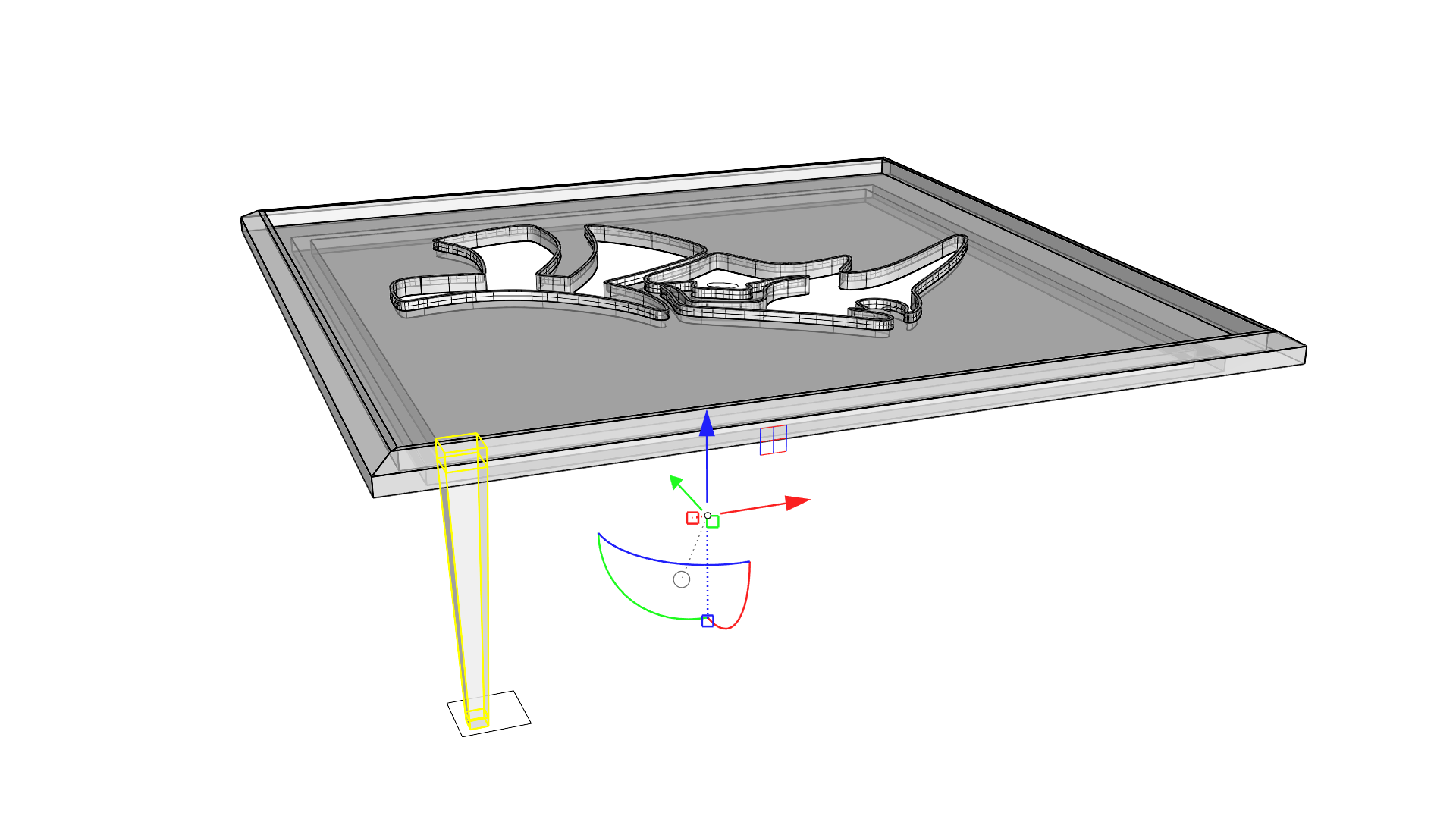
- Select both the leg and the foot polysurfaces and note that the
Gumball
is located at the bounding box center of both objects by default.
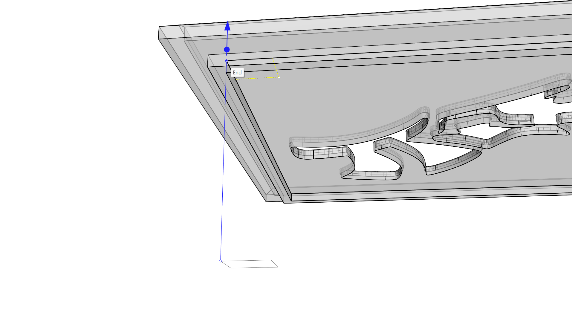
- Double-click the
Gumball
origin and relocate it to an End Osnap at the top corner where the leg and brace meet.
- Click and drag the 2 axis XY plane handle while holding down , to 2D scale the leg and foot by eye. Scaling through the plane handle will maintain the leg length in the same Z axis height.
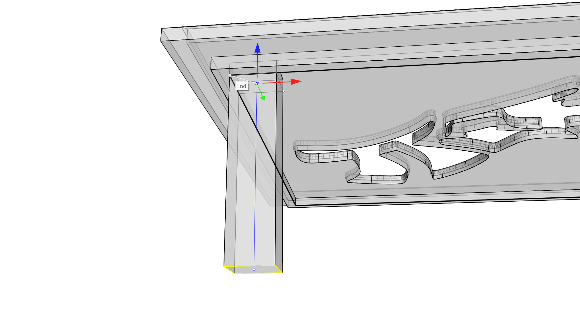
- With the leg and foot objects still selected, click the Settings circle handle on the
Gumball
and choose Relocate Gumball.
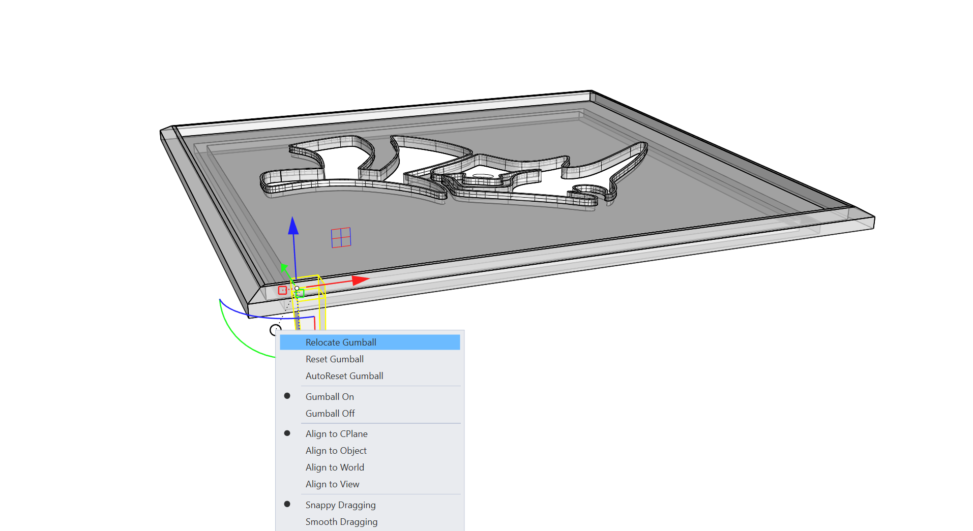
- Type 0 and press and then hold to enable Ortho snap as you define the X and Y axis directions for those Gumball handles. This is an alternate way of relocation versus double clicking.
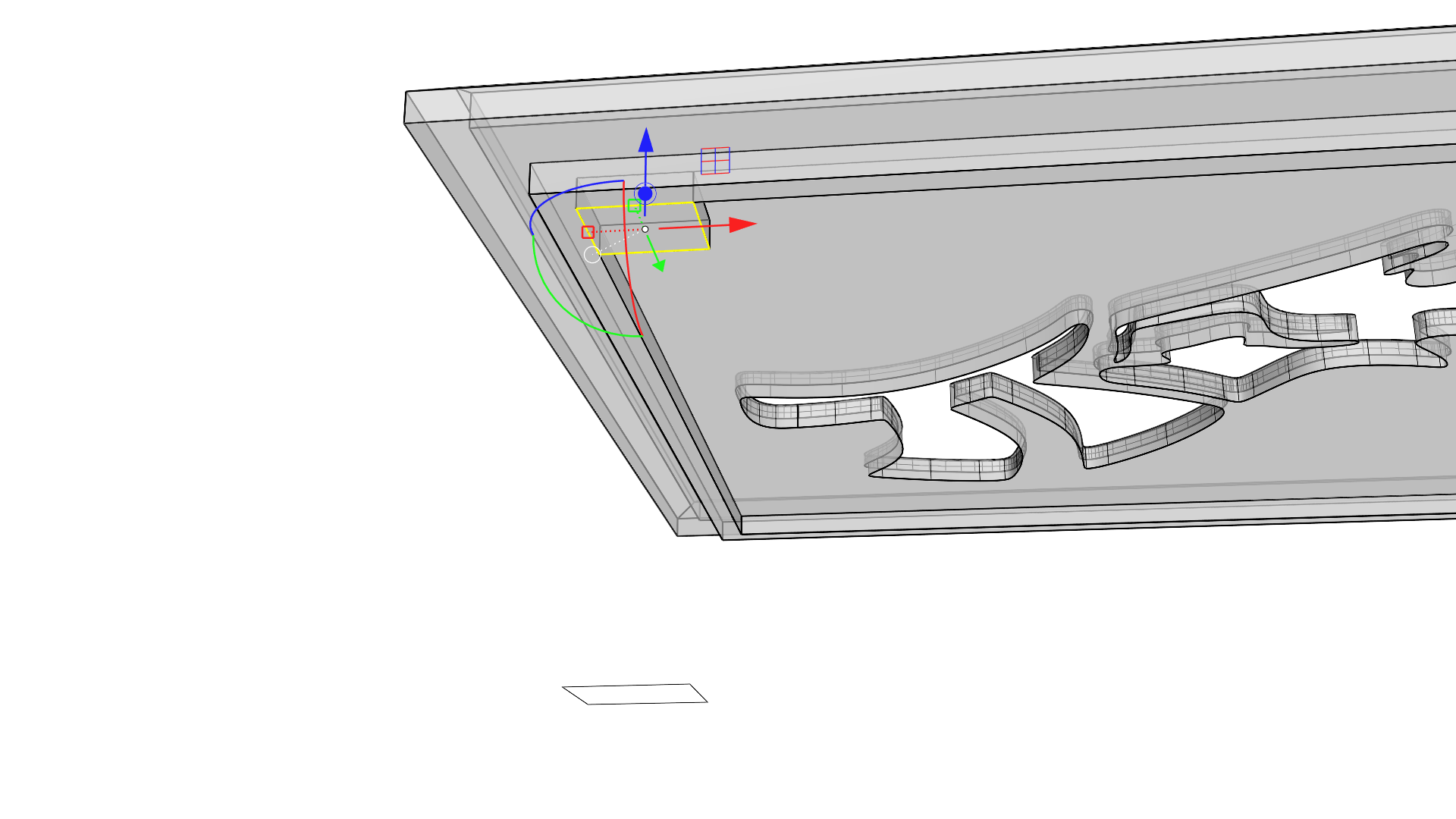
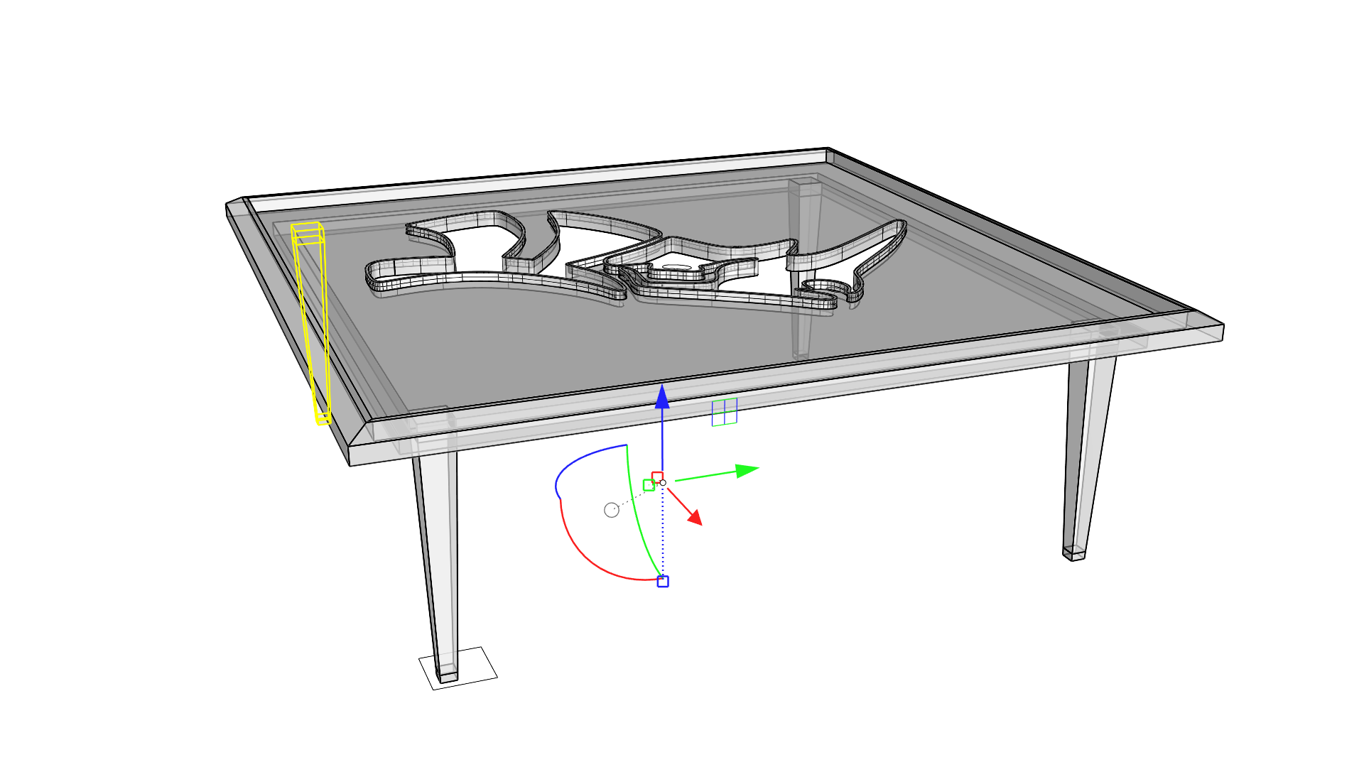
- Click and drag on the Z axis Rotation handle and tap the key to make a copy of the leg and foot selection. Hold the key down before releasing to enable Ortho mode and make a copy at the adjacent corner of the table.
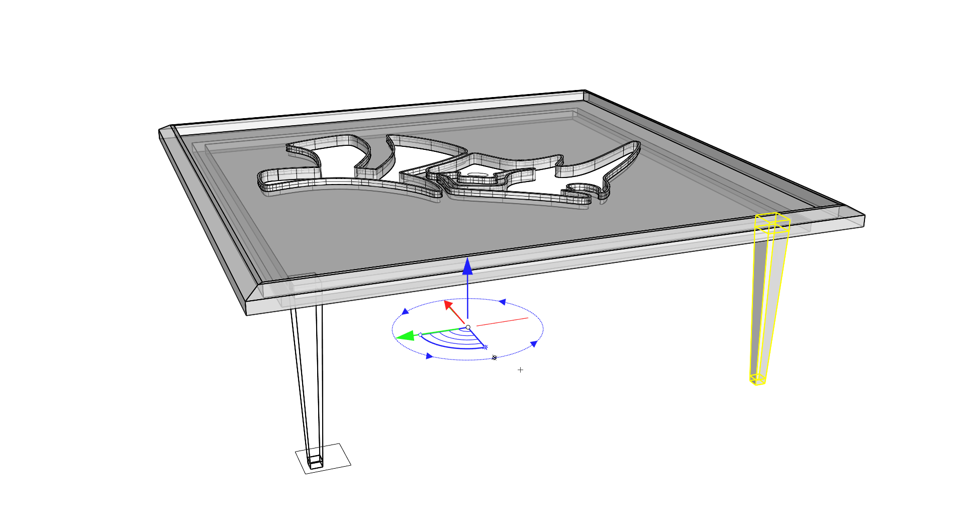
- Repeat this step two more times for the other legs, but do so while the objects are still selected.
 GumballRelocate
will not persist for multiple selections.
GumballRelocate
will not persist for multiple selections.
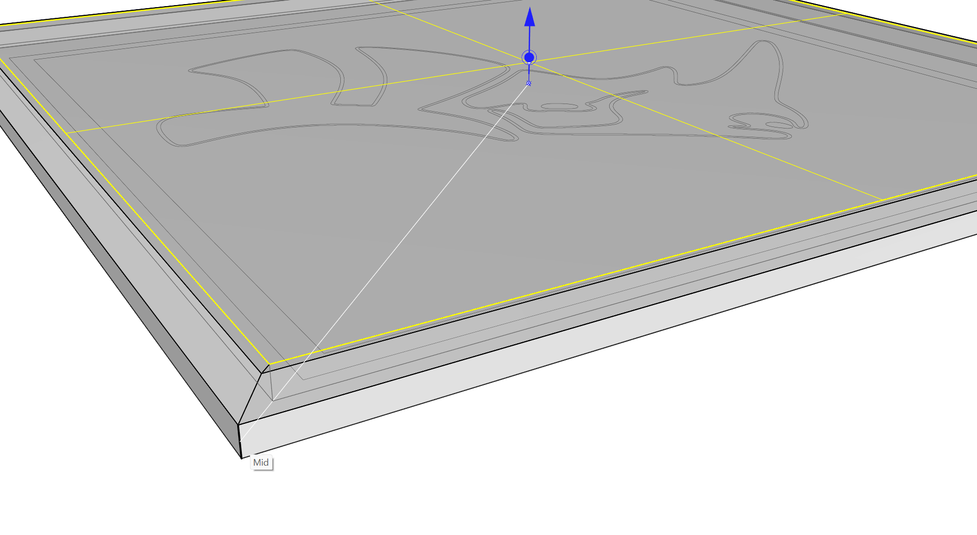
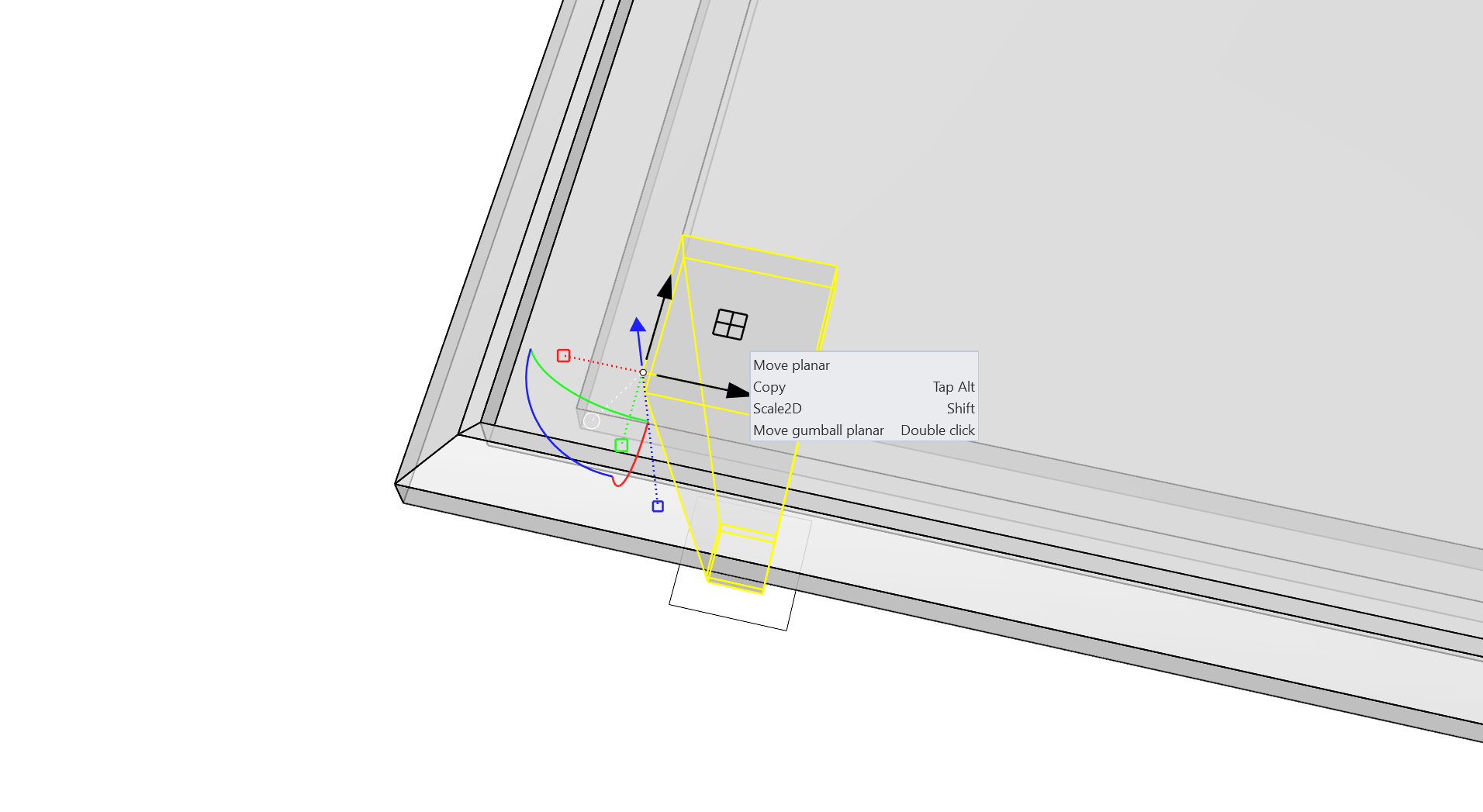
- Sub-object select an edge along the pocket of the table.
Creating the Glass
This will be the easy part after all we’ve learned in the past steps! We’ll use a straight edge of the table as the starting point for creating the glass top.
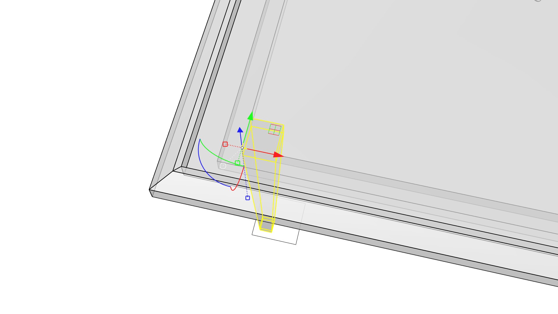
- Use the Y axis Extrude handle to extrude the edge into a surface ending at an End Osnap at the other end of the pocket in the tabletop.
- This creates a new plane that we can use to model the inset glass top for the table.
- Select the new planar surface and use the Z axis Extrude handle to extrude it down ending at a Mid Osnap along an edge defining the depth of the pocket.
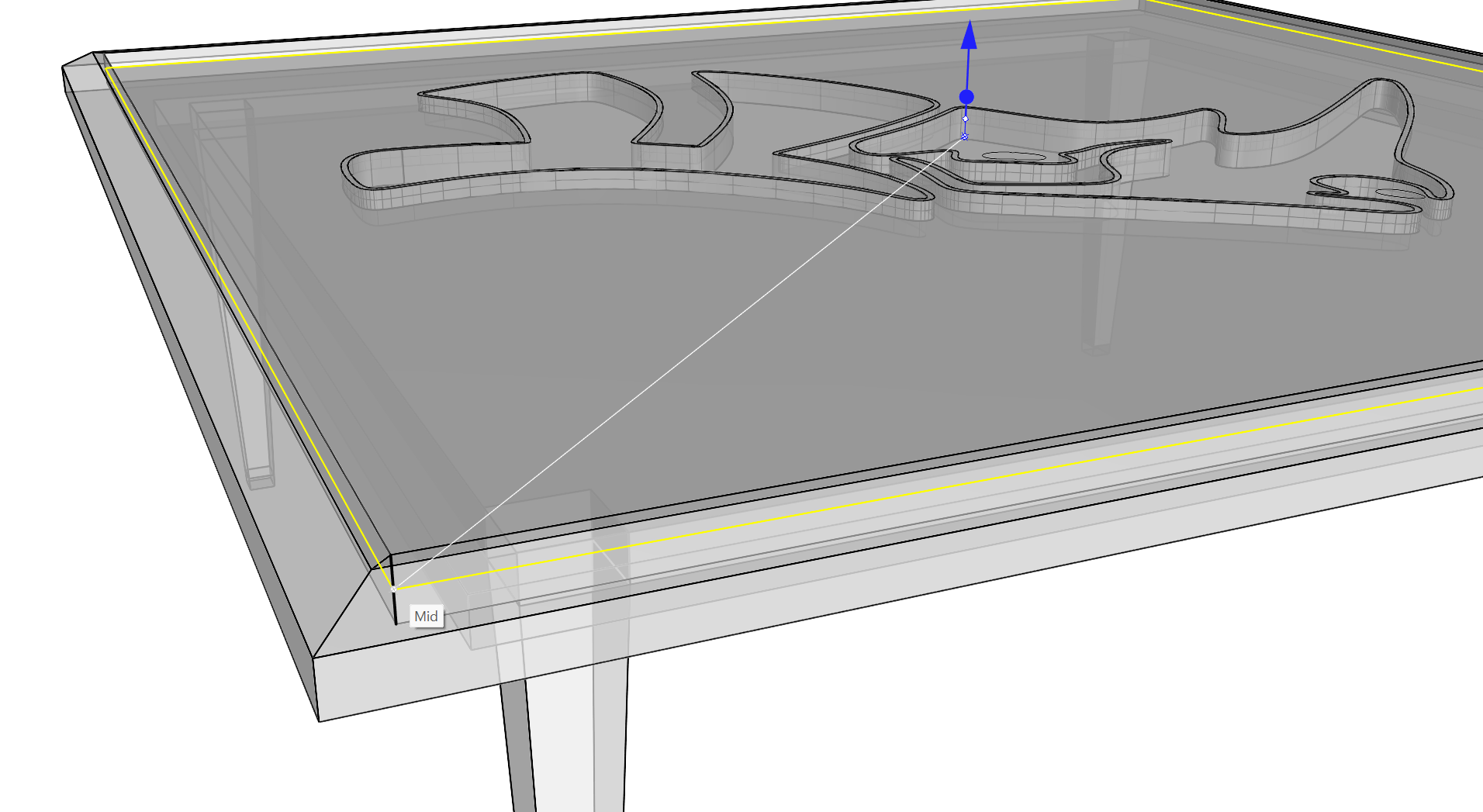
- This new extrusion will rest on the Rhino logo Boss created earlier as both meet at the Midpoint Osnap of the pockets depth.
- Select the Rhino logo eye and nostril curves and click and drag them up using the Z axis Cut handle. Release the drag once the cursor is through the extrusion.
- This creates a couple of holes in the glass top of the table.
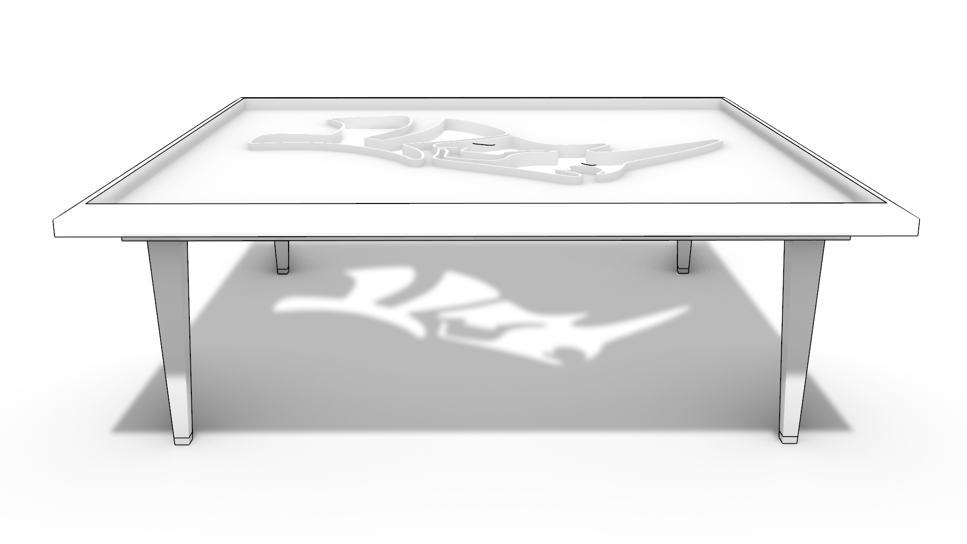
- Switch the viewport to the Monochrome display mode to visualize the design.