What you will learn
In this tutorial, learn how to create a 3DM file that contains team or project-specific settings. Create custom annotation styles, hatch and linetype definitions, as well as “layer templates” for drawings. Start each projcet with this custom template file. Share with colleagues and keep consistency across your design deliverables.
- Create and add custom hatch patterns
- Create and add complex linetypes to define electricity, batting or piping
- Set linewidths for printing
- Create Section Style definitions that can be applied and edited across objects and layers
- Create a template of layers
- Set your views custom view
Introduction
In this tutorial, you will learn how to develop a custom Rhino 3DM template that establishes a consistent graphic and documentation framework for your team or project. We will configure annotation styles, hatch patterns, linetypes, and layer structures to create a coordinated drawing environment - one that reflects your project’s graphic language and documentation standards. The resulting template can then serve as the base file for new Rhino projects, providing a consistent organizational and visual framework from the outset.
By the end of the tutorial, you will have a reusable 3DM template that streamlines project setup, minimize repetitive configuration, and establish a shared standard for drawings and design documentation across your team.
Setting Up the Template
Before defining individual graphic elements, we’ll first establish the basic structure of the template. The goal is to create a clean starting point that is organized, easy to navigate, and flexible enough to adapt to different projects.
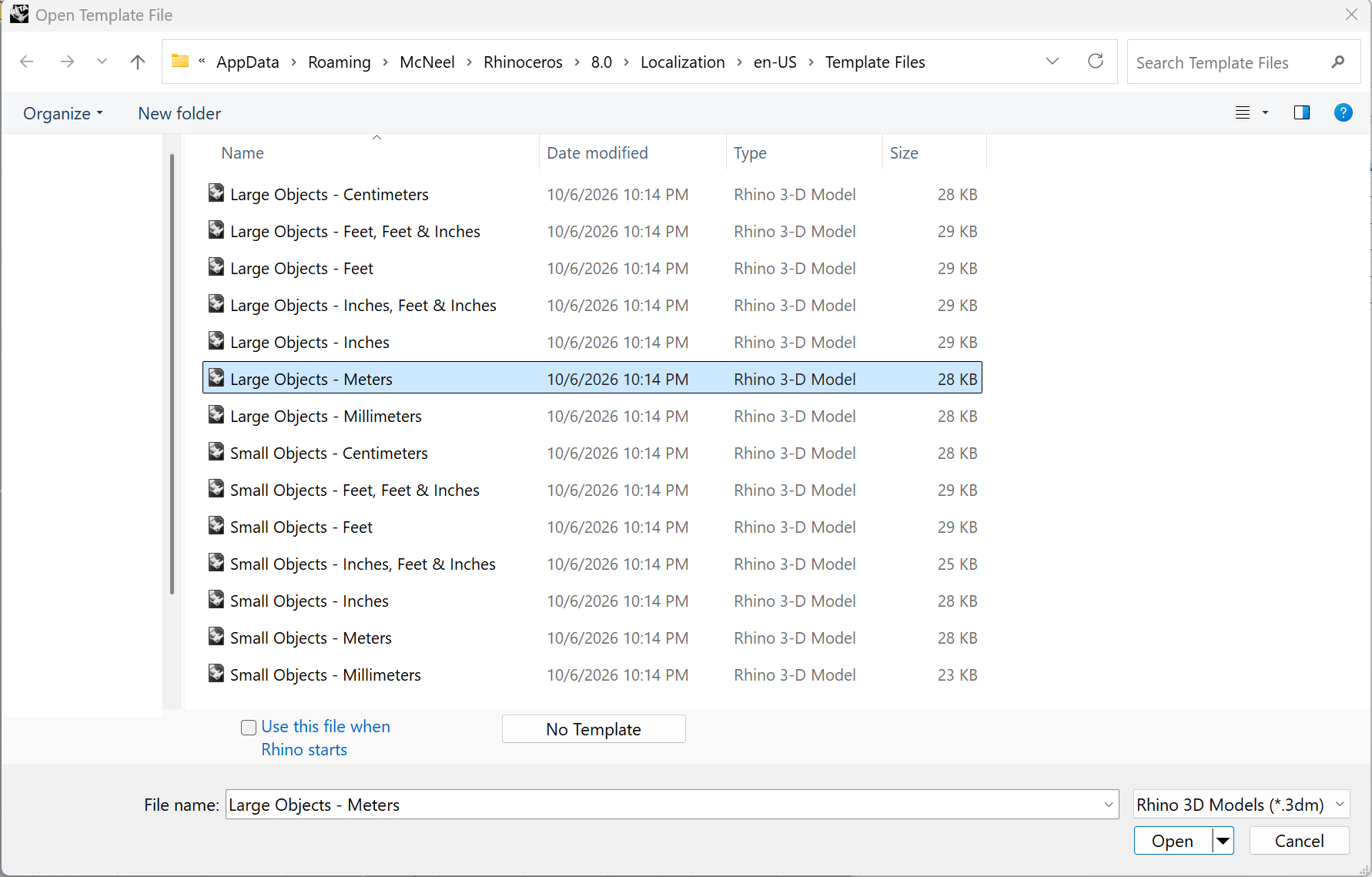
A practical way to create a custom template is to begin with one of the default templates provided with Rhino. These templates already include basic document settings, units, tolerances, and other useful configurations that can be adjusted to suit your workflow. For this example, we will start with Large Objects - Meters template and use it as a foundation for creating our own architecture template.
Start by opening a new Rhino file File > New and choose Large Objects - Meters template file.
When you save a .3DM file as a Rhino template, the template can preserve many document-level settings, including:
- Units and tolerances
- Annotation styles
- Dimension styles
- Hatch Patterns
- Linetypes
- Layers
- Layouts and page settings
- Grid and snap settings
01 – Establish the Layer Structure
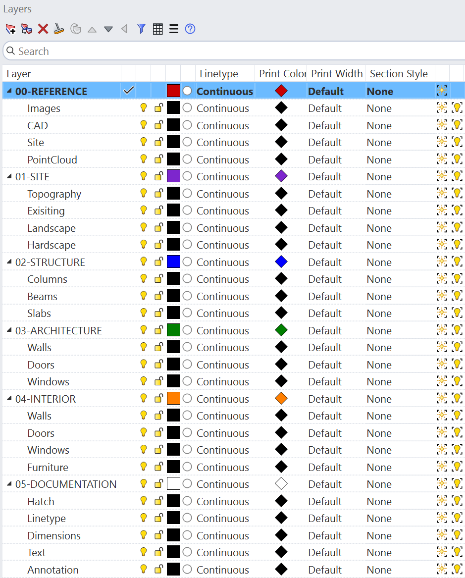
The layer structure forms the organizational backbone of the template. Rather than creating layers on a project-by-project basis, we’ll establish a standardized hierarchy that can be reused across projects.
Consider organizing layers according to the way your team typically develops and documents a project.
A good layer structure keeps your Rhino model organized and makes it easier to find and manage objects.
1. Start with the main categories
Create a small number of main layers based on the type of information in your project.
For example:
 00 - REFERENCE
 01 - SITE
 02-  STRUCTURE
 03 _ ARCHITECTURE
 04 _ INTERIOR
 05 _ DOCUMENTATION
2. Add sublayers for specific element
Each main layer can contain sublayers for the individual elements within that category.
For example:
    00 - REFERENCE
    - Images
    - CAD
    -Site
    -PointClouds
    01 - SITE
    - Topography
    - Exisiting
    - Landscape
    - Hardscape
    02 - STRUCTURE
    - Columns
    - Beams
    - Slabs
    03 - ARCHITECTURE
    - Walls
    - Floors
    - Doors
    - Windows
    04 - INTERIOR
    - Walls
    -  Doors
    - Windows
    - Furniture
    05 - DOCUMENTATION
    - Dimensions
    - Text
    - Annotation
    - Hatch
    - Title Block
3. Keep the hierarchy simple
Keep the layer stucture simple, clear, and streamlined, with a hierarchy that reflects your workflow and project requirements. The template should provide a flexible framework rather than trying to anticipate every layer a future project may need. Use a consistent naming convention for layers and sublayers so the file remains easy to navigate and team members can quickly understand where new geometry belongs.
Set Up the Core Documents Properties
Now, from the Document Properties we begin to define the settings that should be consistent across every project created from this template.
To access Document Properties, Go to Tools > Options, or run the  Options
command.
Options
command.
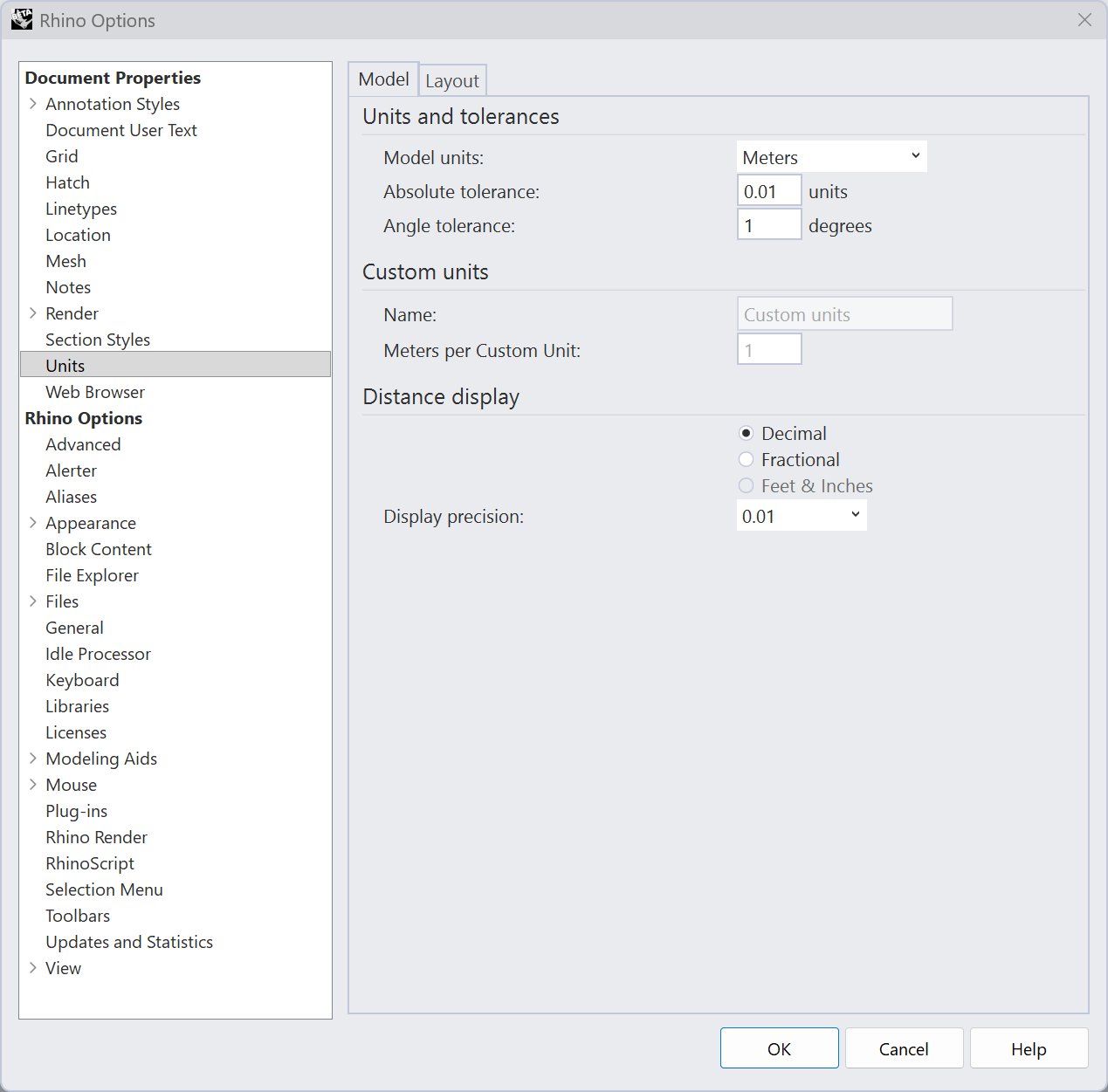
02 – Set the Units
The model units are particulary important because Rhino uses them to interpret all numerical input. For example, entering 10 with the document set to meters creates a 10m distance. Changing the units later can affect how geometry and numerical values are interpreted.
Set the Absolute Tolerance
Within the Units settings, define the Absolute Tolerance. Tolerance determines how precisely Rhino calculates and joins geometry. For most architecture and interior projects, a tolerence of: 0.01mm provides a suitable starting point.
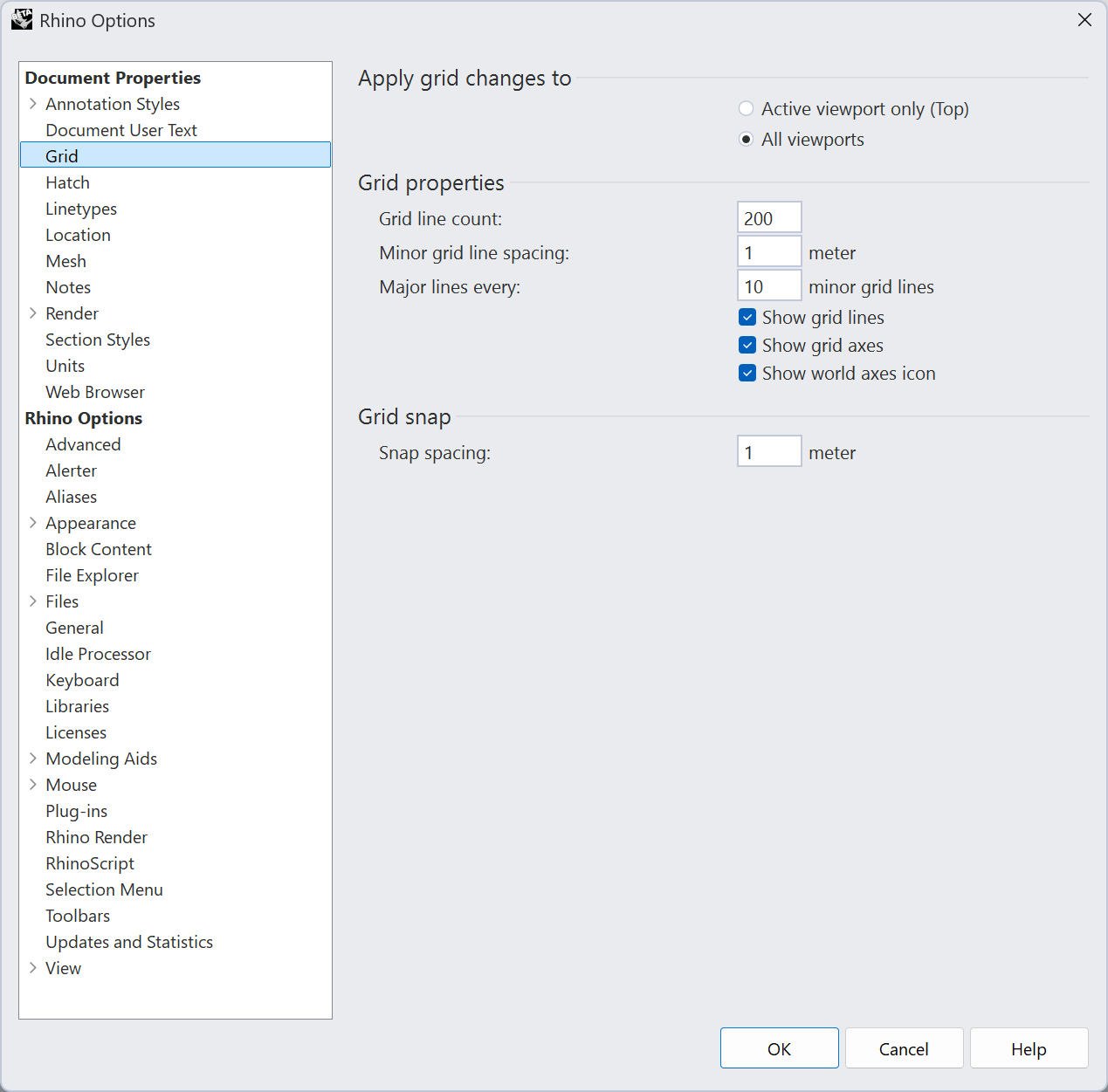
Configure the Grid
The Grid should support the scale at which your team typically works.
For a meters-based architecture template, you might establish:
- Grid line count:
200. - Minor grid spacing:
01 meter. - Major grid line spacing:
10 minor grid lines. - Snap spacing:
01 meter.
03 – Linetypes
Rhino includes a number of predefined linetypes, but a project may require patterns that are not available by default.
Creating custom linetypes allows you to define a graphic language that is specific to your documentation standards. More importantly, maintaining these linetypes within the template ensures that the same visual conventions can be reproduced across projects.
There are multiple way to access the Linetypes Panel, one of the easiest is by typing linetypes in Rhino’s command line.
To create a custom linetype:
- Download and open the template-architecture Rhino file.
- Run the
 Linetypes
command to open the Linetypes panel.
Linetypes
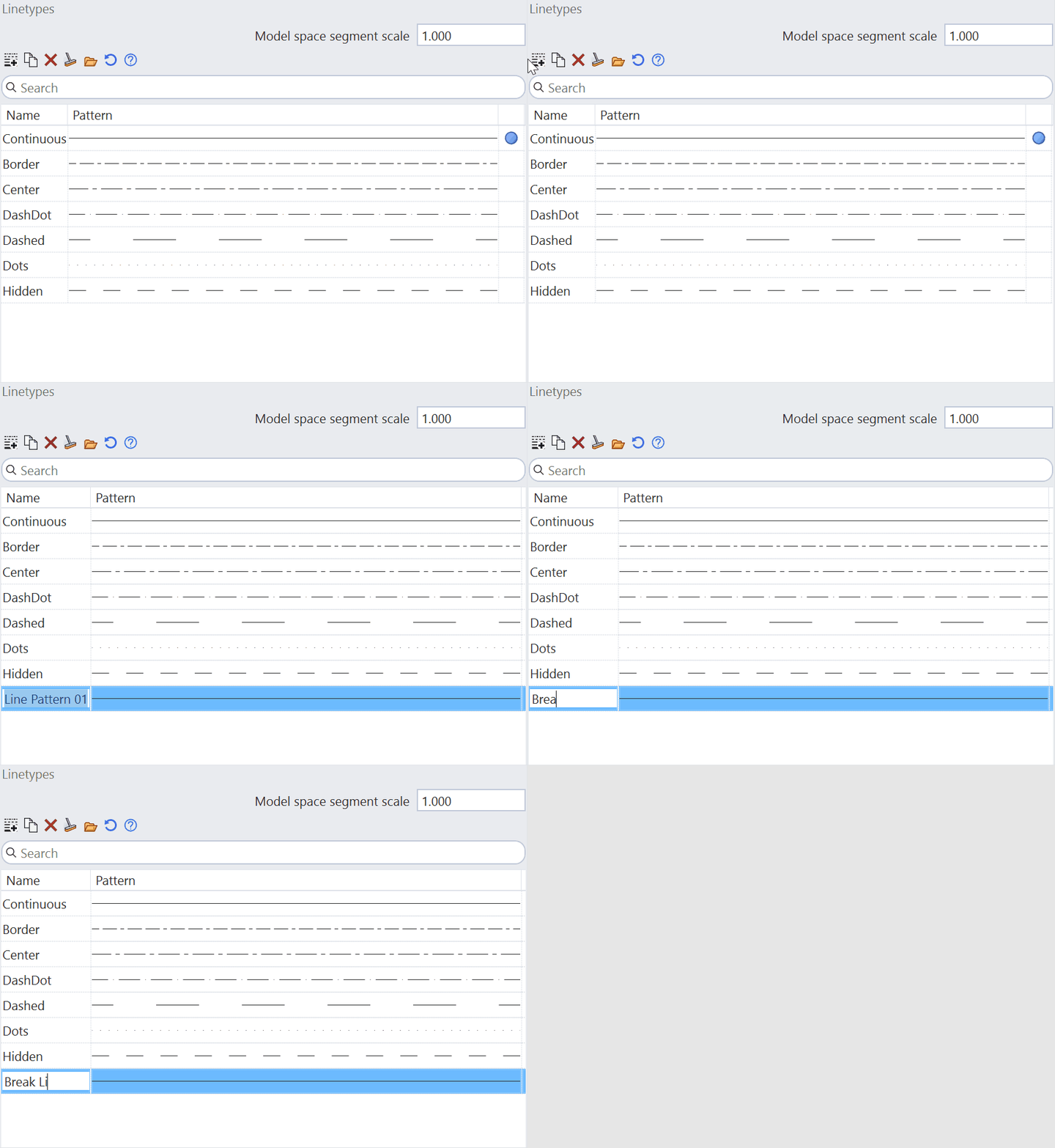
command to open the Linetypes panel. - In the
Linetypes panel, click theNew button linetypes_add
to create a new linetype. (https://docs.mcneel.com/rhino/9/help/en-us/image/icons_v9/linetypes_add.png)
linetypes_add
to create a new linetype. (https://docs.mcneel.com/rhino/9/help/en-us/image/icons_v9/linetypes_add.png) - Name the new linetype Break Line. Press .
- Maximize the Viewport.
- In the
Linetypes panel, scroll down to theShapessection: - Select
Select Shapes...- Select the Break Line symbol.
- Press .
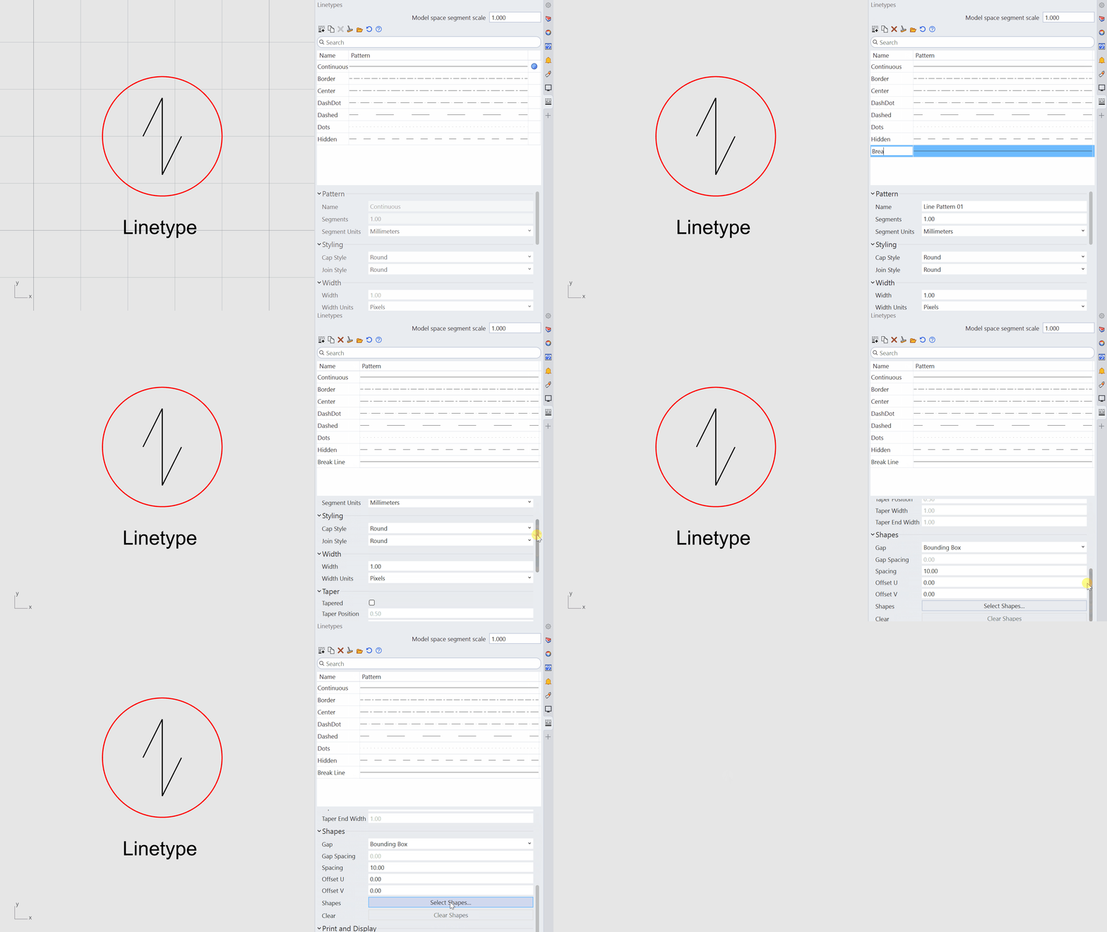
Now your custom linetype has been successfully added and saved as part of your linetype library.
04 – Hatch Patterns
Hatch patterns are an important part of the drawing language. They help communicate materials, construction conditions, cut elements, and areas of emphasis without relying entirely on text and linework.
Just as with linetypes, Rhino provides a library of default patterns. However. you may want to create a cutom library relevant to your documentation standards.
To create a custom Hatch Pattern:
- Download and open the template-architecture Rhino file.
- Run the
 HatchPattern
command. Press
.
HatchPattern
command. Press
. - At
Choose hatch pattern option, selectAdd. - At
Pattern tile rectangle, trace thered rectangle. - At
Select curves and points that define the pattern, select each curve in order to define the pattern. Press . - At
Hatch pattern name:, type: roof_slate. Press . - Press again.
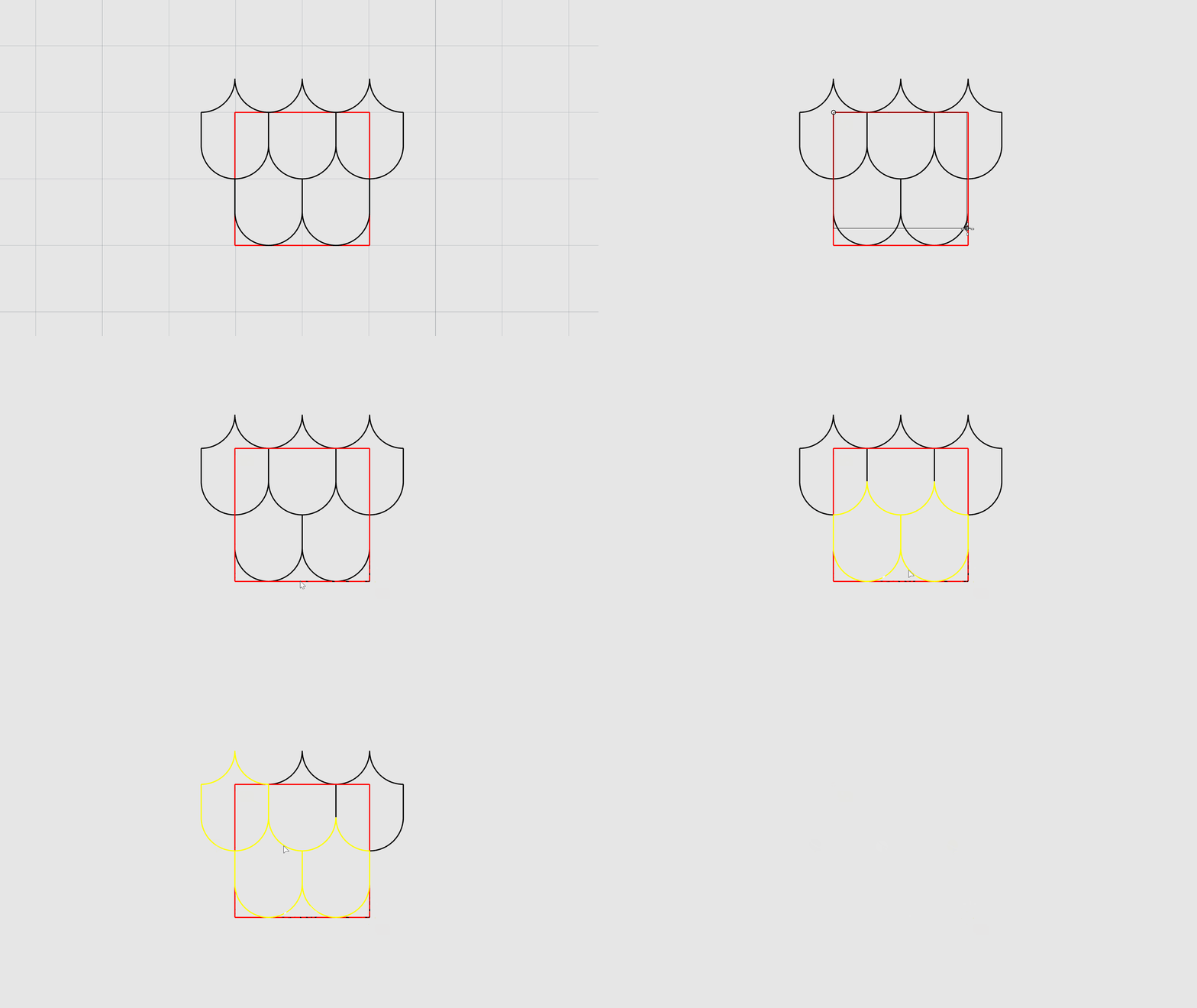
Now your custom Hatch Pattern has been successfully added and saved as part of your Hatch library.
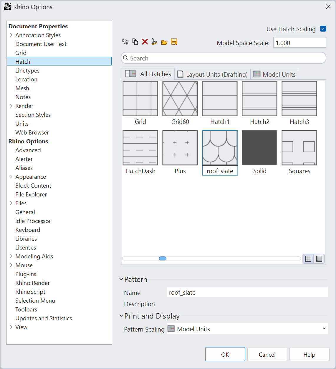
Architecture and Design Studios can now build a custom library of Hatch Patterns tailored to their standards and workflows. The new custom hatches are saved within the Document Properties and can be included in the Template File, making them readily available for future projects and easy to share across the team.
05 – Section Styles
One of the most usefule features for standardized Rhino documentation workflow in Rhino 9 is the Section Styles system. A Section Style controls how an object appears when it is cut by a clipping plane. Depending on the configuration, it can control properties such as:
- Hatch pattern
- Hatch scale
- Linetype
- Display color
- Print color
- Print width
To create a predefined Section Styles that will be included in your Rhino template:
- Run the options
command.
- Find
Section StylesunderDocument Properties. - Click
Newto create a newSection Style. - Give the style a descriptive name.
- Set the desired Hatch Pattern, Linetype, and Colors.
- Click
Okto save the style.
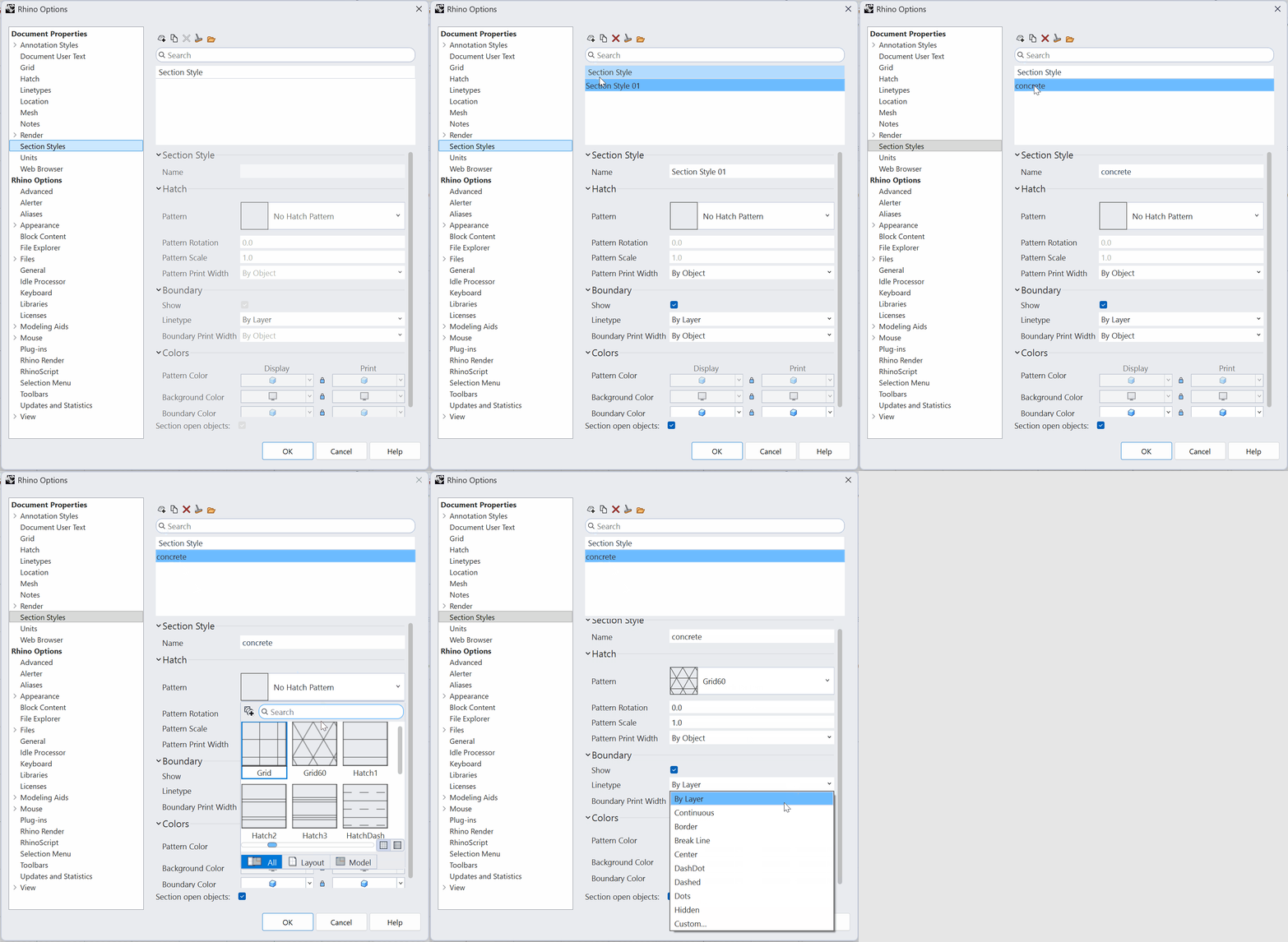 Because the Section Style is associated what the object’s layer, the same graphic treatment can automaticlly be applied to multiple objects using that layer.
You can assign a specific Section Style to each layer, allowing different elements of your model to display with different section graphics.
Here’s how:
- In your
 Layer
panel, find the
Layer
panel, find the Section Stylescolumn. - Find a layer you want to assign a Section Style to.
- Click on
Noneunder theSection Stylecolumn. - A dialog box will appear displaying all the settings and options associated with the section styles.
- Click on the
Document StylesDrop down menu. - Select your predefined style.
06 – Inserting a Title Block Using the Block Content Panel
The Block Content Panel in Rhino 9 allows you to access predefined blocks and insert them into your document. The Title Block library includes ready-made title blocks for use in drawing layouts.
To access the Block Content Panel and the Title Blocks Library:
- Run the
 BlockContent
command in Rhino. Press
.
BlockContent
command in Rhino. Press
. - Find the the
Title Blocksubfolder.
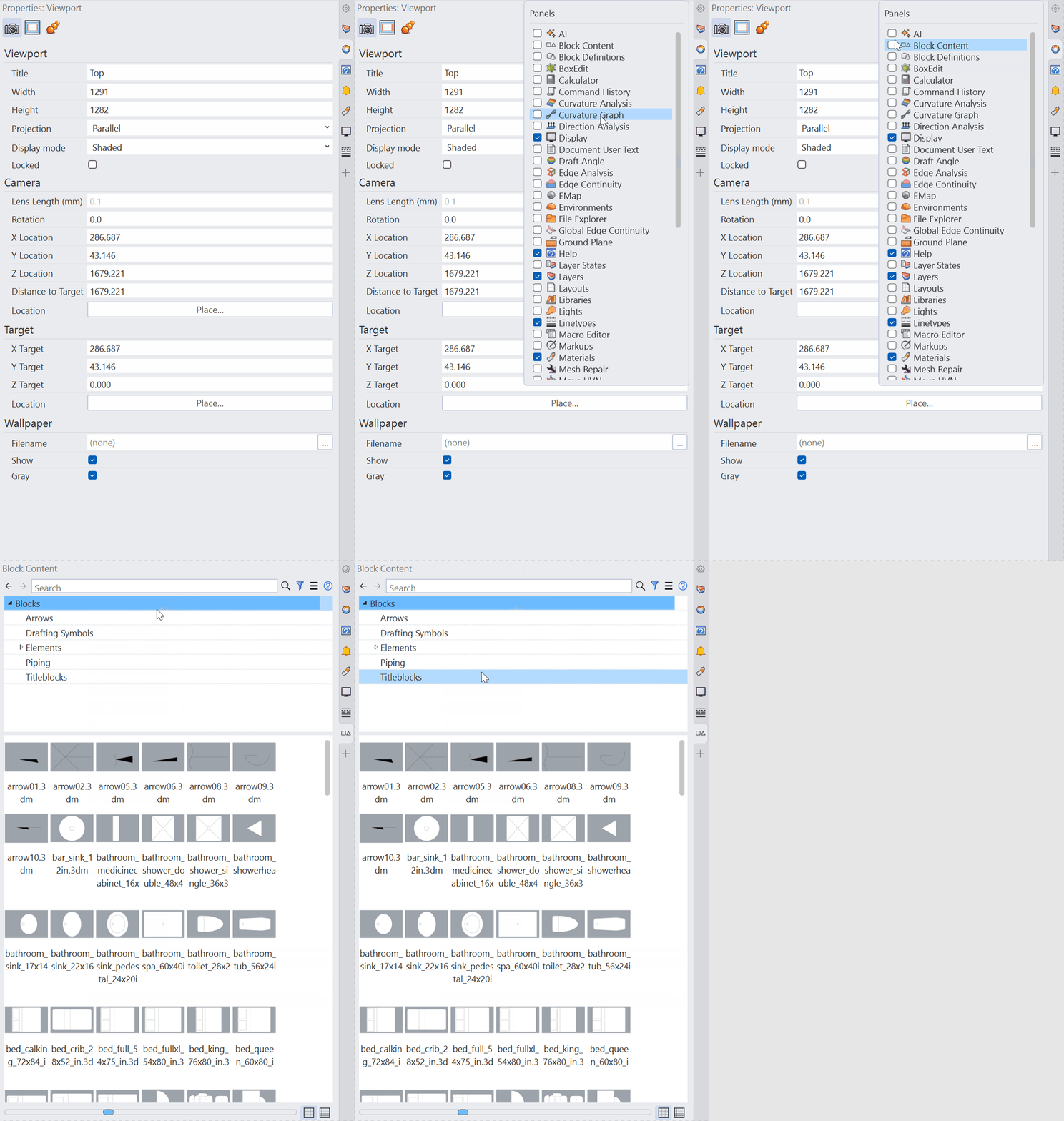
To insert a Title Block from the Block Content Panel:
- Find a Title block size that maches your layout size.
- Drag and drop it into your Layout as a Block Instance.
The Title Block is now ready to use as part of your drawing layout.
Connecting Document User Text to Title Blocks
A Rhino file contains more than geometry and graphic settings. It can also store custom information about the document itself. This is where Docuement user text becomes useful. The main advantage is that it gives the template a place to store information that travels with the project, so instead of manually changing these values in every layout, an automated title block can retrieve the information from the document.
Document User Text allows you to create your own key-value pairs and store information directly inside the .3dm file. This makes it particularly useful when building a standarized project template.
Document User Text is essentially a small metadata system built into the Rhino file.
You define a:
KEY and assign it a VALUE
For example:
| KEY | VALUE |
|---|---|
| Project name | Vill 01 |
| Project number | 0543 |
| Designer | Drew Lynes |
| Date | 10/07/2026 |
To define your own Key-Value pair:
- Run the options
command.
- Find
Document User TextunderDocument Properties. - Click
Add. - Enter a
Keyto identify the information. - Enter a corresponding
Value. - Click
Okto save the information.
At this point, your Rhino template has started to develop several different layers of information:
Layers
Organize geometry.
Linetypes
Define line patterns.
Hatches
Define materials and section graphics.
Section Styles
Define how cut geometry is represented.
Document user text
Stores information about the project and the document itself.
Once you have all your configurations set up, it is time to save the file as a Rhino template so it can be reused andshared across your organization.
- Go to
File>Save As Template. - Give your template a clear, descriptive name.
- Click
Save.
Once saved, it can be used as starting point for new projects, ensuring that your established standards and settings are unified.
Conclusion
A well-structured Rhino template provides a consistent and effecient starting point for every project. By setting up standards in advance, you can reduce repetitive work, improve organization, and maintain consistency across your projects and teams.
The takeaway: Build the standard once, save it as a template, and let it streamline every project that follows.