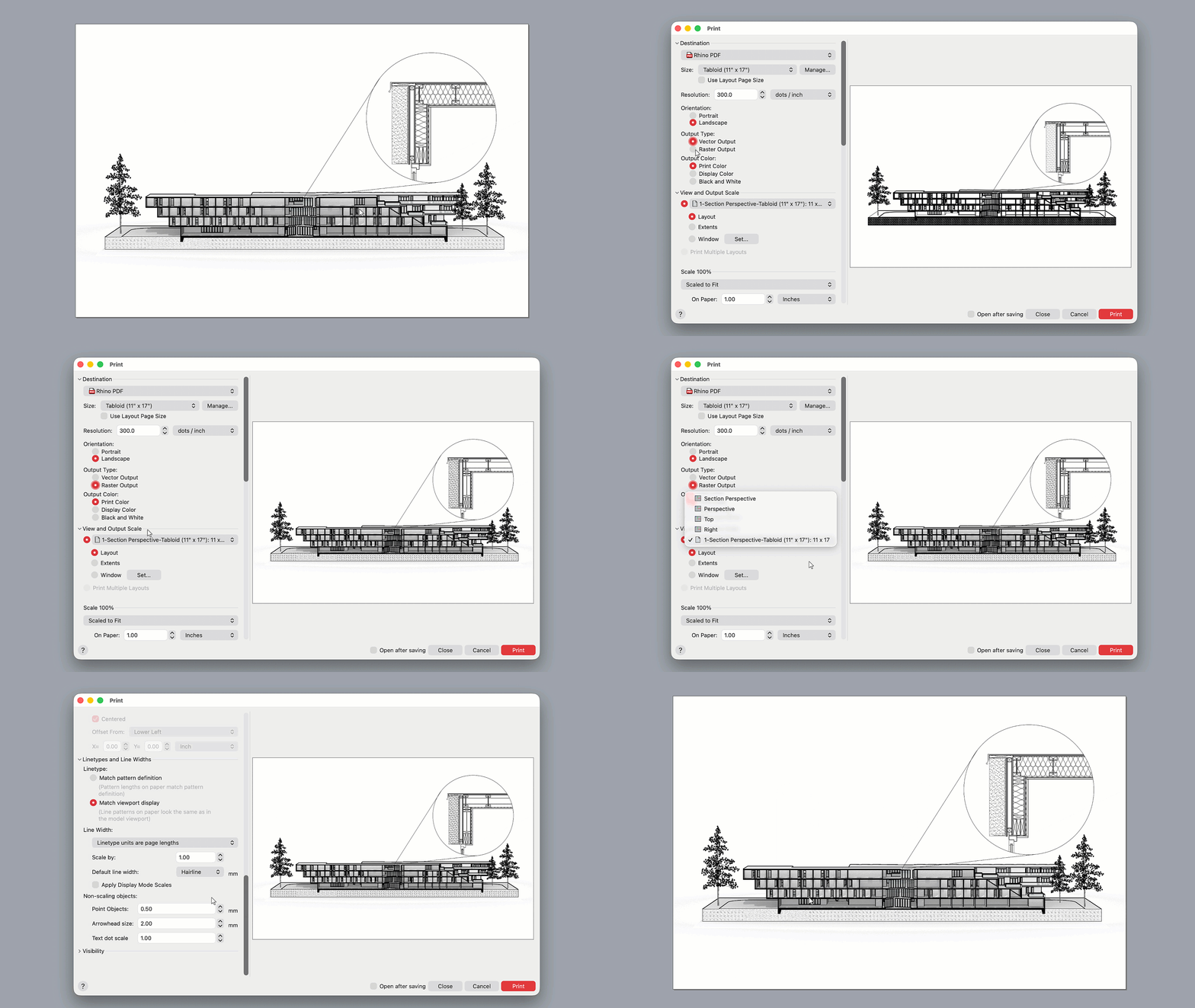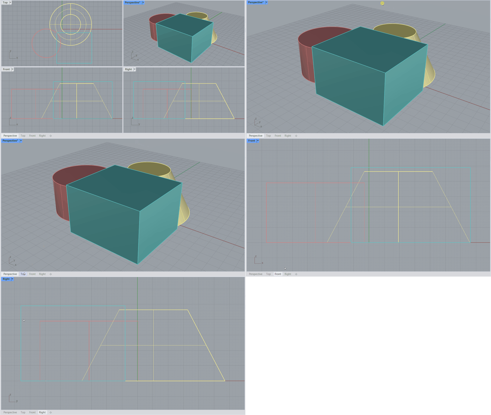
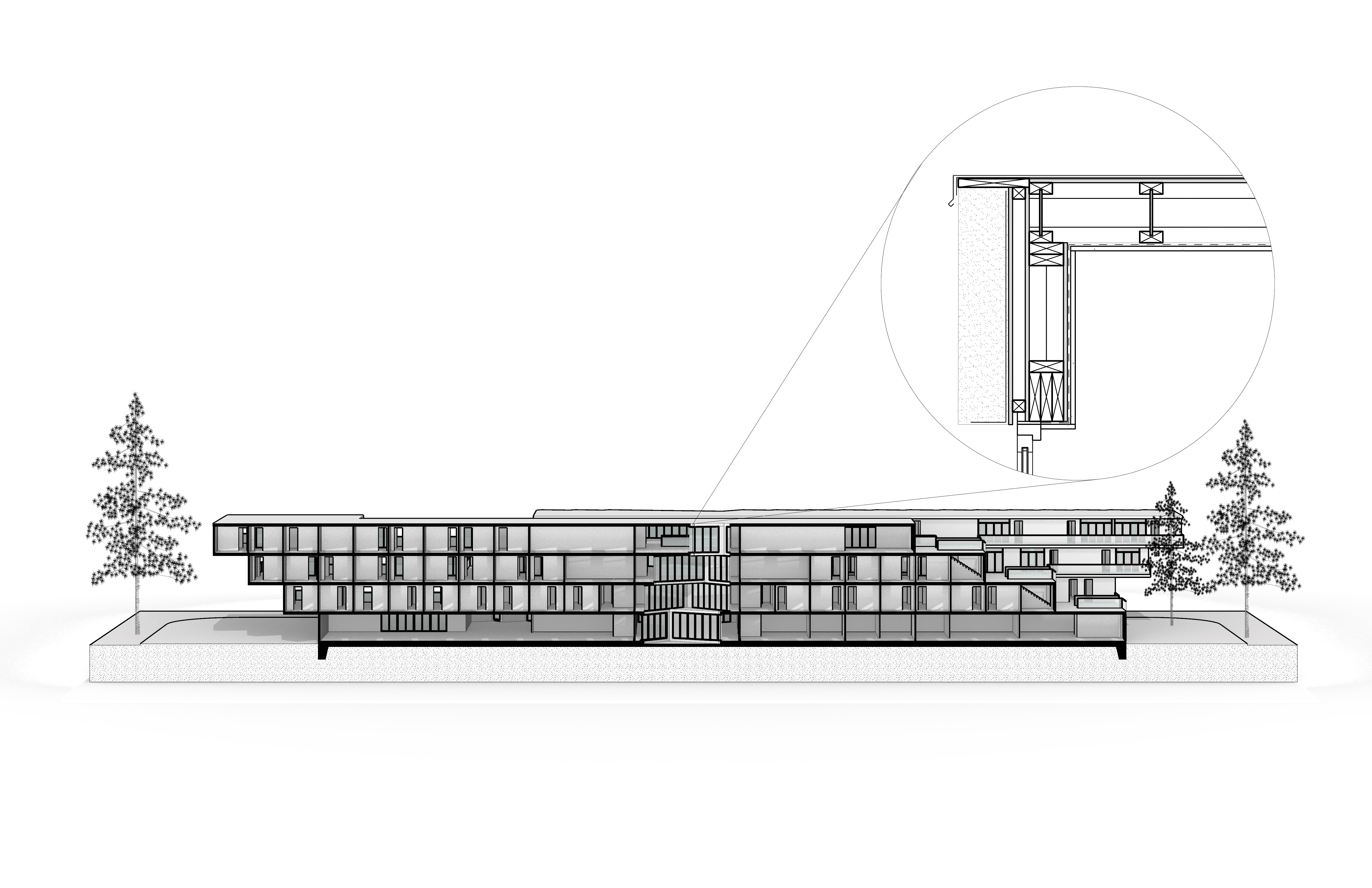
A section perspective is one of the most effective ways to explain a building. It cuts through the model to reveal interior spaces, materials, and levels while preserving the depth and atmosphere of a perspective view. Unlike a conventional flat section, it helps viewers understand not only how the building is organized, but also how the space might feel.
In this guide, we’ll create a live section cut using  ClippingSections
, generate an in-place Clipping Drawing, and control the appearance of the cut with Section Styles. We’ll then turn the straight-on section into a two-point perspective, apply the Concept display mode, add shadows, and save the composition as a Named View. Finally, we’ll place the section perspective on a Layout, add a supporting top view inside a custom-shaped detail border, bring in trees from Rhino’s Libraries panel, connect a personal symbol library, and export the completed sheet as a PDF.
ClippingSections
, generate an in-place Clipping Drawing, and control the appearance of the cut with Section Styles. We’ll then turn the straight-on section into a two-point perspective, apply the Concept display mode, add shadows, and save the composition as a Named View. Finally, we’ll place the section perspective on a Layout, add a supporting top view inside a custom-shaped detail border, bring in trees from Rhino’s Libraries panel, connect a personal symbol library, and export the completed sheet as a PDF.
What you'll learn
- Cut the model with ClippingSections
.
- Generate a linked drawing with
 ClippingDrawings
and project it in place.
ClippingDrawings
and project it in place. - Apply Section Styles to distinguish the building and ground.
- Compose the section using Two-Point Perspective.
- Apply the Concept display mode and add sunlight and shadows with
 Sun
.
Sun
. - Save the composition with
 NamedView
.
NamedView
. - Place the section perspective on a
 Layout
using a
Layout
using a  Detail
.
Detail
. - Add a supporting top view with a Non-Rectangular Detail
.
- Add trees and connect a reusable symbol library.
- Export the finished Layout
with
 Print
as a PDF.
Print
as a PDF.
Before You Start
Let’s make sure your Rhino’s interface is set up the same way as this tutorial before we begin.
- Go to the Window menu.
- Open the Window Layouts submenu.
- Select Default Window Layout.
This configures the toolbars and panels to the same setup and location used here.
In the Status Bar , disable everything except Osnap and Gumball. On the left, in the Osnap Control , check End, Mid and Near and uncheck the rest. This keeps things predictable as we work.
Set Up the Section Cut
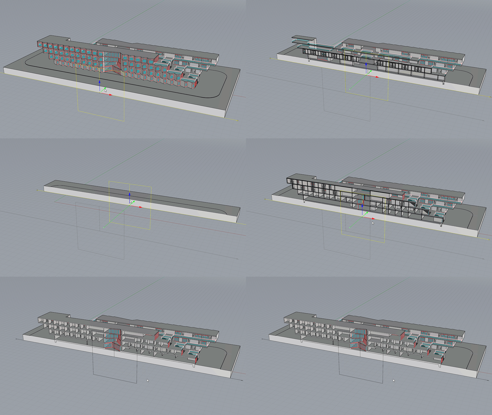
We’ll start by cutting through the building. A Clipping Section is a live plane that slices the model in real time. From it, we’ll extract a 2D Clipping Drawing. Instead of placing that drawing off to the side, we’ll project it in its true 3D location so the rest of the model remains visible behind it.
Create the Clipping Section
-
Download and open the Section Perspective model.
-
Make the
Clipping Planelayer current . -
Run the
ClippingSections
command. -
At the
Select objects to section. Press Enter for allprompt , press . -
With the Mid Osnap , snap the cut to the midpoint of the base.
-
At the
Place sectionprompt, check that the Command Prompt options read:- Dir =
X - CustomDepth =
No - Clip =
Yes - Name =
SEC - LabelMode =
Text - SaveToNamedView =
Yes - Flip =
No
- Dir =
-
Press when done.
-
The model is now clipped, and you can see straight into the interior.
-
If the cut faces the wrong way, select the section and open the
 Properties
panel, then select Flip Direction.
Properties
panel, then select Flip Direction. -
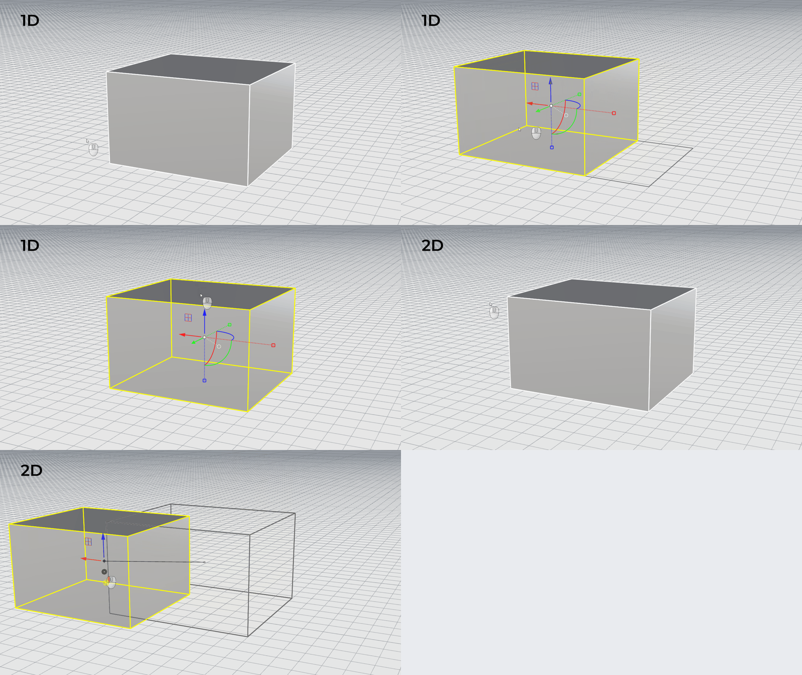
Select the Clipping Plane.
-
Move with the Gumball to the desired cut position you want to show.
Project the Drawing In-Place
Normally, ClippingDrawings
asks for a placement point and drops the 2D linework somewhere on the flat World plane. For a section perspective, we want the opposite: The drawing should stay exactly where the cut is, in 3D space, so the rest of the model reads behind it. That’s what Project in-Place does.
- Continue with your file or download the Section-Perspective-2 model.
- Select the Clipping Plane you just created.
- Run the ClippingDrawings
command.
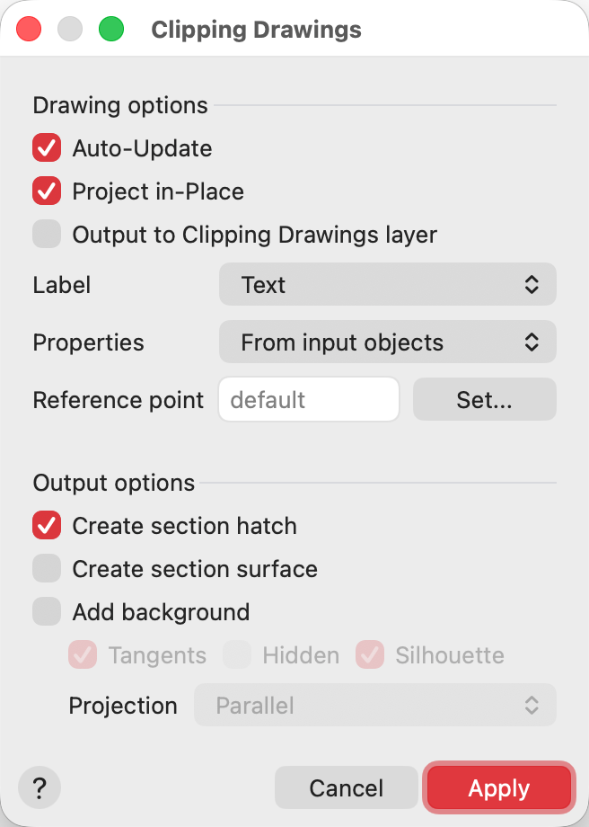
- In the Clipping Drawings dialog, set the options like this:
- Auto-Update =
Yes - Project in-Place =
Yes - Output to Clipping Drawings layer =
No - Label =
Text - Properties =
From input objects - Create Section Hatch =
Yes - Create Section Surface =
No - Add Background =
No - Add Annotations =
No
- Auto-Update =
- Click Apply.
- Notice that Rhino does not ask for a placement point. Rhino generates the drawing directly on the section plane, in its true 3D location.
- Select the Clipping Plane and move it a short distance. Watch the in-place drawing follow the plane and re-cut the model live.
 Block
: copy, move, or rotate it as one associated set, double-click it (or run
Block
: copy, move, or rotate it as one associated set, double-click it (or run  EditClippingDrawings
) to edit it in place, or explode it to cut its link to the 3D model. A static drawing can help create rich illustrations, as you can further refine the linework.
EditClippingDrawings
) to edit it in place, or explode it to cut its link to the 3D model. A static drawing can help create rich illustrations, as you can further refine the linework.Assign Section Styles
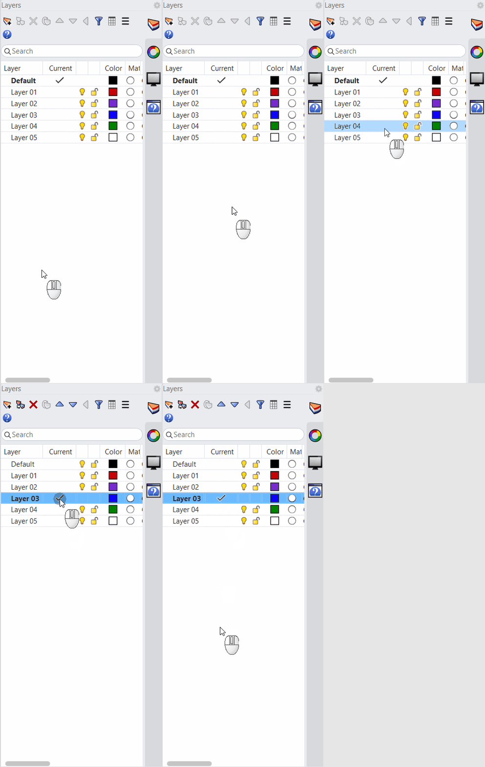
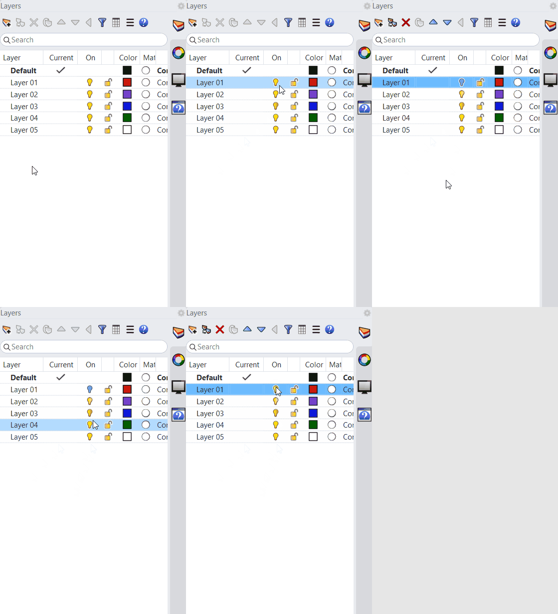
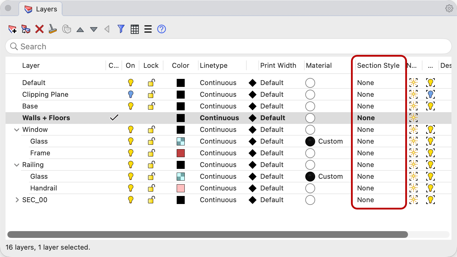
A Section Style controls the cut face’s appearance, including its hatch, fill, and color. Assigning a style to each layer helps the materials read at a glance, with a solid poché for the cut floor and walls and a looser fill for the ground beneath them. You can set these in the Section Style column of the Layers panel.
- Continue with your file or download the Section-Perspective-3 model.
- Open the
 Layer
panel.
Layer
panel. - Make the
Walls + Floorslayer current -
Turn off
the
Clipping Planelayer. - Find the Section Style column (you may need to widen the panel to see it) for the
Walls + Floorslayer. -
Select
the
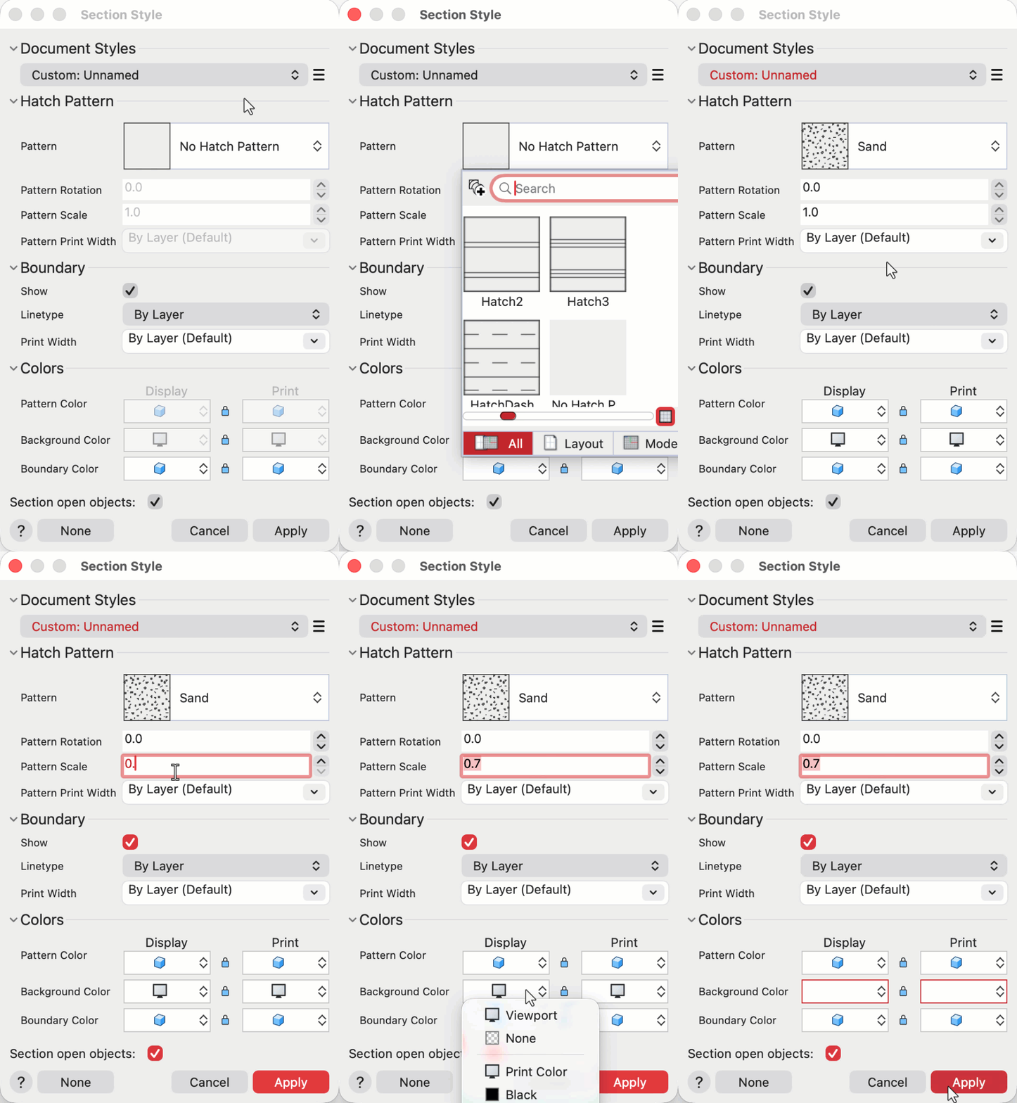
NoneSection Style cell for this layer, top open the dialog. - Assign a style with a Solid black hatch. This gives the cut a solid black poché.
- For the
Baselayer, open the Section Styles dialog:- Assign a style with the Sand hatch, so the ground reads as a lighter, granular fill.
- Adjust its scale so the grain reads at your drawing size.
- Add a white background color to it.
- Select Apply.
- For the
Window / FrameandRailing / Handrailsub-layers:- Assign the same Solid fill.
- Change its Pattern Color from By Object to Black.
- Select Apply.
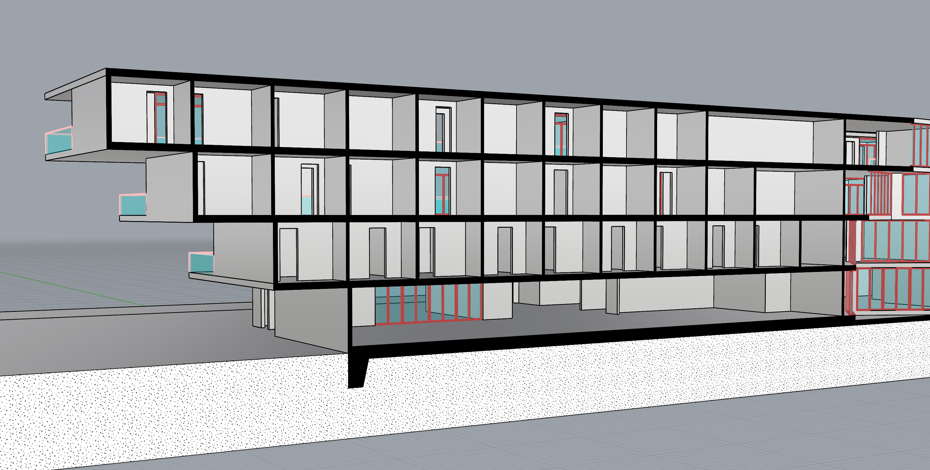
- The clipping section updates live and displays the added Section Styles.
Compose the Section Perspective
Here’s the move that turns a flat section into a section perspective: we start from a straight-on view, then switch that viewport to two-point perspective so the space gains depth while the verticals stay vertical. We’ll present it with the Concept display mode and save the framing as a Named View.
Frame the View in Two Point Perspective
- Continue with your file or download the Section-Perspective-4 model.
- Maximize the viewport.
-
Turn on
Clipping Planelayer. - Select the Clipping Plane.
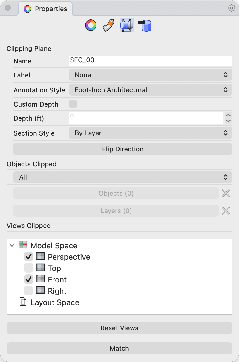
- In the Properties
panel, under Views Clipped, enable
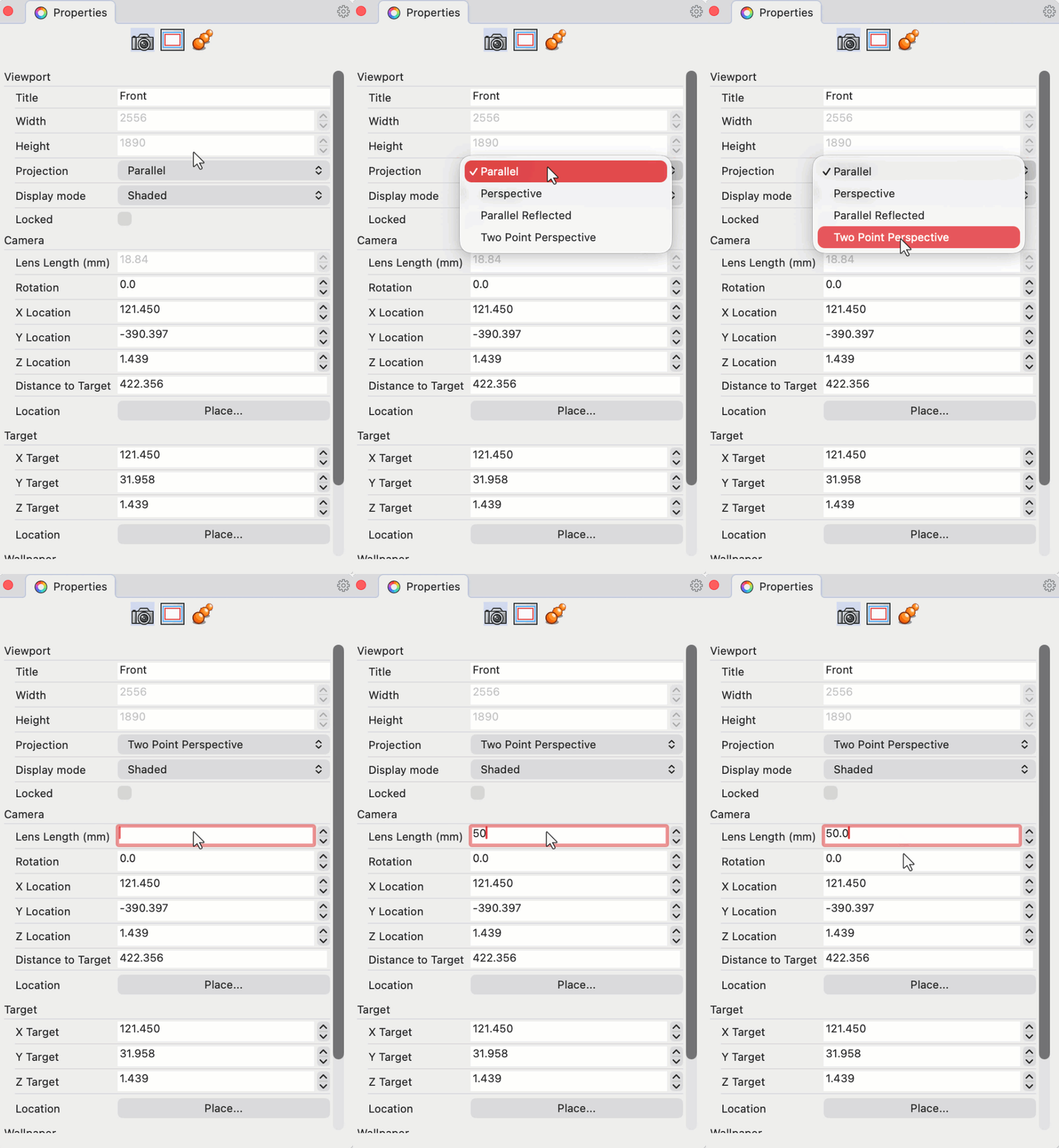
Front. Then turn off theClipping Planelayer. - With nothing selected, go back to the Properties panel to access Viewport Properties:
- Set Projection to
Two-Point Perspective. This adds depth to the straight-on section view while keeping all vertical lines upright. - Adjust the Lens Length until the perspective and framing look right.
- Set Projection to
- To adjust the composition without losing the section’s parallel alignment:
- For zooming with precision, hold + right-click.
- For panning, hold + right-click.
Apply the Concept Display Mode
- Continue with your file or download the Section-Perspective-5 model.
- In the viewport, Display Mode to Concept. The model now appears as a soft, sketch-style presentation view, while the in-place section drawing remains crisp against the cut model.
- Run the
 PrintDisplay
command.
PrintDisplay
command. - At the
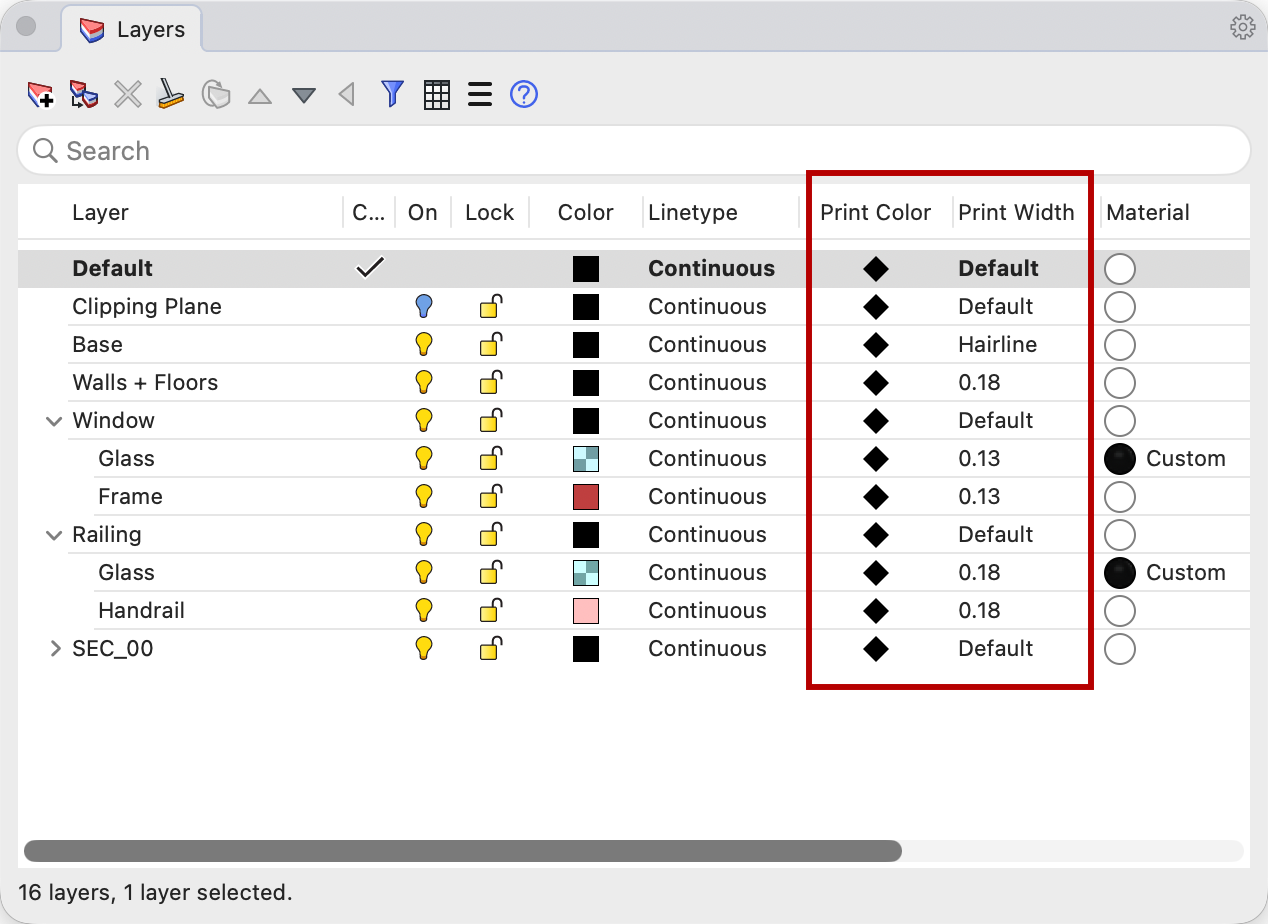
Print Display (Model Viewports)prompt , setState=On. Press Enter. Now, you can preview the Print Color and Print Width settings assigned to the rest of your linework. - To add shadows and depth, run the
 Grid
command and set
Grid
command and set ShowGrid=No,ShowGridAxes=No, andShowWorldAxes=Noin the prompt . Press Enter. The grid should now disappear from the viewport. - Run the Sun
command to open the Sun panel:
- Turn the sun On
- Under Date and Time, adjust the date, time, and location until the shadows fall as desired. Concept mode displays the changes immediately.
Save the View
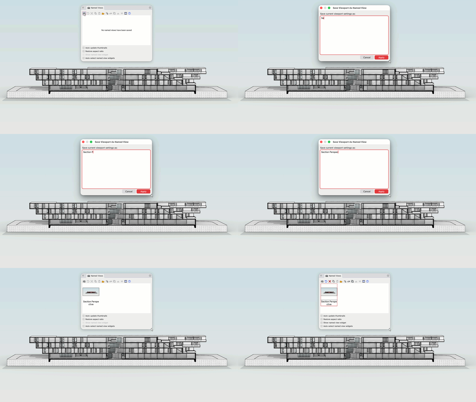
We’ll reuse this exact framing on a Layout later, so let’s save it as a Named View.
- Frame the view the way you want it presented.
- Run the NamedView
command to open the panel.
- Select the + (Save As) button.
- Name the view
Section Perspectiveand press .
Compose the Layout
Now we’ll place the section perspective on a page for presenting or printing. A Layout
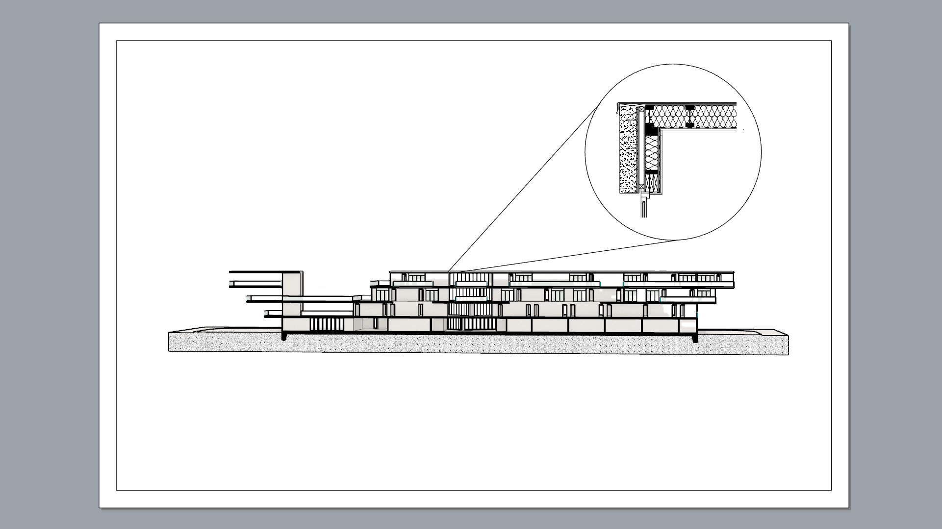
is a paper space sheet that looks into your model through a viewport called a Detail. To give the drawing an editorial feel, we’ll frame it with a Non-Rectangular Detail, a detail border shaped by a curve instead of a plain rectangle.
Create the Layout
- Continue with your file or download the Section-Perspective-6 model.
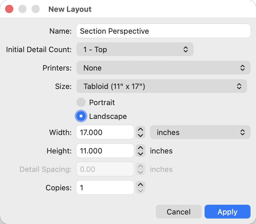
- Run the Layout
command to open the New Layout dialog.
- Name =
Section Perspective - Initial Detail Count =
1 – Top - Printers =
None - Size =
Tabloid (11" × 17"), Landscape - Copies =
1 - Select Apply.
- Name =
- The new Layout opens containing the Detail
window, showing the model from the
Topview. - Double-click inside the Detail to activate it. A Detail is essentially a window into Model Space from your Layout or “sheet”.
- With the Detail active:
- In the NamedView
panel, double-click on the
Section Perspectiveview you saved earlier. - In the
, change the
Display Mode
to
Concept. - Double-click outside the detail to deactivate it and return to the Layout.
- In the
- To change the Layout’s background color to white:
- Run the
 Options
command.
Options
command. - Browse to the Appearance page.
- In the
Layoutsection, select the color swatch and change it to White - Select Apply to close the dialog.
- Run the
- Run PrintDisplay
and set it to
Offfor now.
Frame with a Non-Rectangular Detail
A rectangular frame is fine, but a shaped border turns the drawing into a vignette and draws the eye to what matters. Non-Rectangular Details can follow any closed curve.
- Continue with your file or download the Section-Perspective-7 model.
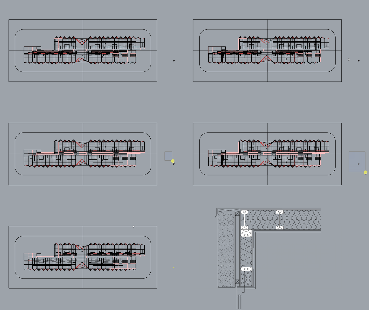
- Using the Viewport Tabs to switch to the Top viewport.
- Select to the wall/roof assembly detail to the right of the view.
- In the prompt , type ZS and press Enter. This the will zoom-in to the selection.
- Save a NamedView called:
wall-roof assembly. - Using the Viewport Tabs , return to the Section Perspective layout.
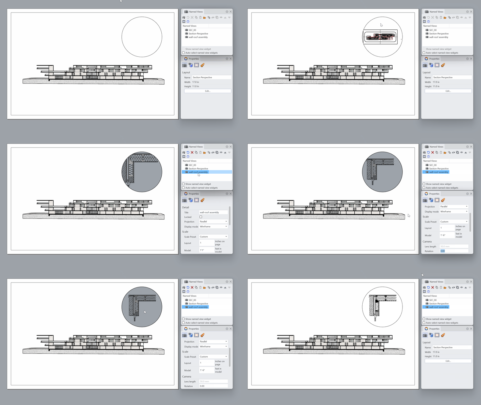
- Run the
 Circle
command:
Circle
command:
- At the
Center of circleprompt , select a point in the top right corner of the Layout. - Then type 2 for the radius.
- At the
- Run the
 Detail
command:
Detail
command:
- At the
Detail Viewportprompt, selectFromCurve - At the
Select borderprompt, select the circle you just created.
- At the
- Double-click inside this Detail to activate it.
- In the NamedView
panel, double-click on the
wall-roof assemblyto restore this view. - Zoom-in and Pan to adjust or use the Properties
panel to set the scale.
- Double-click outside the view to deactivate it.
- Run the
 Line
command to create the callout lines.
Why Non-Rectangular Details?Real designs are rarely rectangular, and neither are the best drawings of them. Shaped borders let you highlight an element, create focus, or cleanly mask out areas you don’t want shown, no manual cropping.
Line
command to create the callout lines.
Why Non-Rectangular Details?Real designs are rarely rectangular, and neither are the best drawings of them. Shaped borders let you highlight an element, create focus, or cleanly mask out areas you don’t want shown, no manual cropping.
Add Symbols and Finish the Sheet
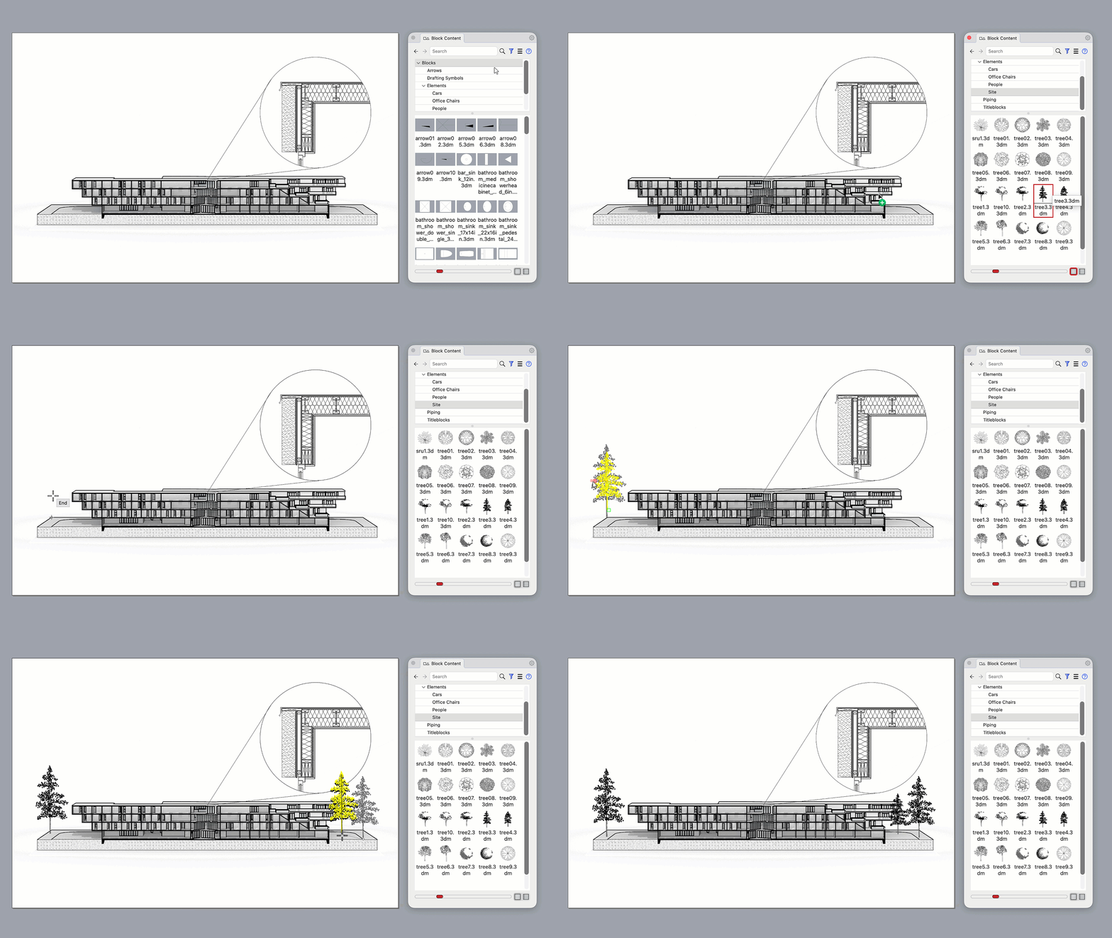
Finish the composition by adding a few drafting symbols. For this example, we’ll add trees to provide context, but you can use the same process for scale figures, furniture, north arrows, and other symbols.
- Continue with your file or download the Section-Perspective-8 model.
- Make the
Treeslayer current . - Open the
 BlockContent
panel.
BlockContent
panel. - Browse the drafting-symbol folders and select a tree.
- Drag and drop the tree directly onto the Layout, placing it over the section perspective detail.
- Press Apply through the Insert File Options and Insert dialogs.
- At the
Insertion pointprompt, click to place the tree on the sheet. - Use Move, Rotate, Scale, or Mirror to adjust its position and size.
- Repeat the process to add more trees as needed.
Bring in Your Own Symbol Library
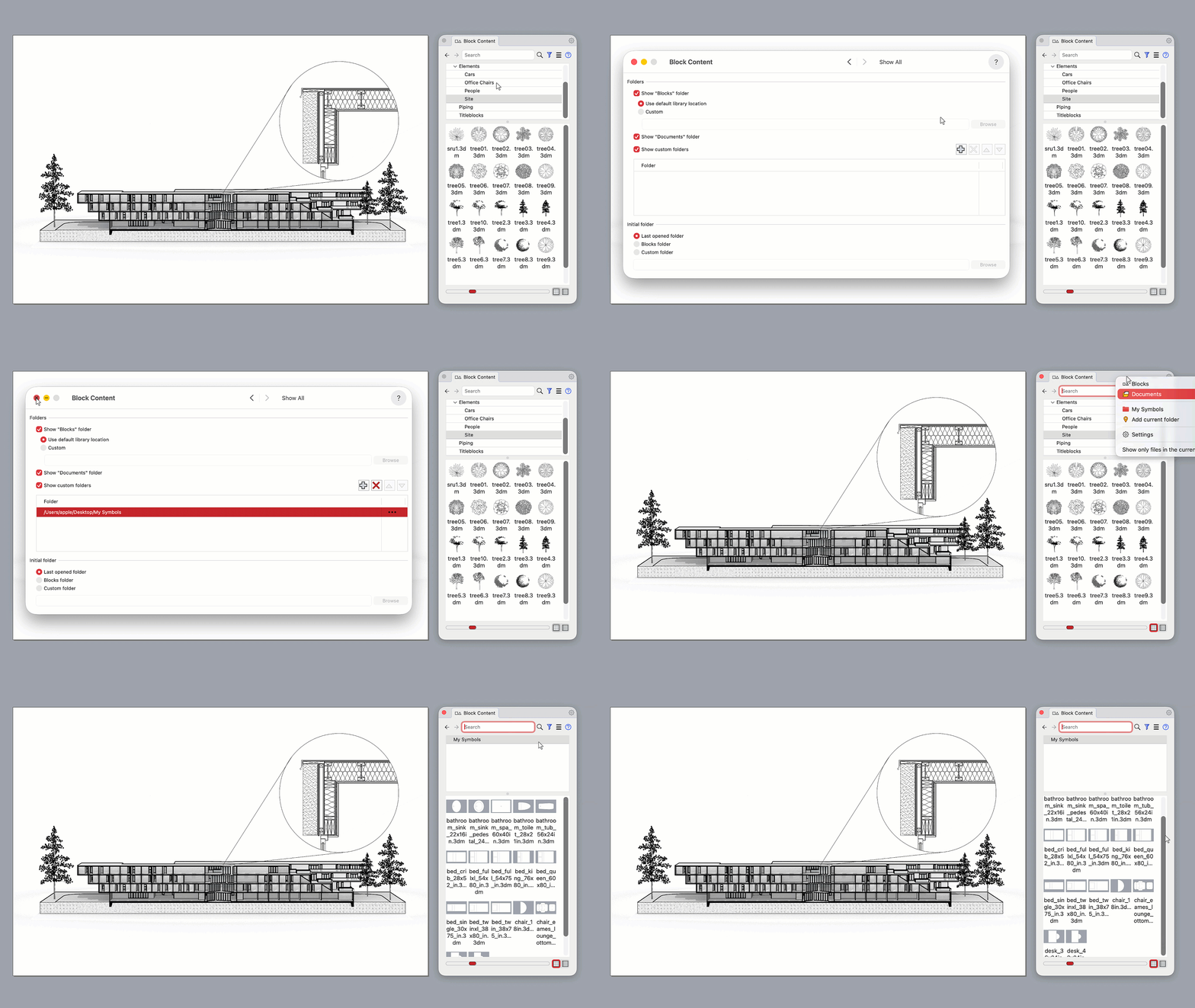
You can connect a folder containing your own studio symbols, making them easily accessible across Rhino files.
- In the Block Content panel, open the Block Content menu and select Settings.
- Click the Add (+) button, then select the folder containing the symbols you want to add.
- Return to the Block Content menu. Your folder should now appear as an available content source. Select it to display its contents.
- You can now drag and drop these symbols into your current and future Rhino drawings.
Export the Drawing
With the Layout complete, export it as a shareable, print-ready PDF.
- Continue with your file or download the Section-Perspective-Final model.
- With the
Section PerspectiveLayout open, run the Print
command. - Under Destination, select
Rhino PDF. - Set the following print options:
- Size:
Tabloid (11" × 17") - Resolution:
300 dots/inch - Orientation:
Landscape - Output Type:
Raster Output. This preserves the shading, shadows, and other visual effects from the Concept display mode. - Output Color:
Print Color. This uses the print colors assigned to your layers and objects, preserving the graphic hierarchy you established for the drawing.
- Size:
- Under View and Output Scale, select the
Section PerspectiveLayout and choose Layout rather than Extents or Window. - Under Scale, select
Scaled to Fit. The scale should display as100%. - Check the preview to confirm that the complete Layout fits correctly on the sheet.
- Click Print.
- Choose a file name and destination, then click Save to export the PDF.