The editing operations in this section break objects apart, cut holes in them, and put them back together. Some of these commands join curves to curves, or surfaces into polysurfaces, and break a composite curve or polysurface into its components.
The commands:
![]() Join
,
Join
,
![]() Explode
,
Explode
,
![]() Trim
and
Trim
and
![]() Split
apply to curves, surfaces, and polysurfaces.
Split
apply to curves, surfaces, and polysurfaces.
Join
The
![]() Join
command connects curves or surfaces together into one object.
Join
command connects curves or surfaces together into one object.
Join turns:
- Lines that touch end to end into polylines.
- Curves that touch end to end into polycurves.
- Surfaces and polysurfaces that touch on an edge into polysurfaces or solids.
When a curve is selected first, surface edges or mesh edges can be joined with the curve to create a polyline or polycurve.
Join Curves into a Polycurve:

- Window-select all the curves. The Command History displays 5 curves added to selection.
- On the Edit menu, select
 Join
. The
Command History
displays 5 curves joined into one closed curve.
Join
. The
Command History
displays 5 curves joined into one closed curve.

The separate curves have been assembled into a single closed polycurve.
Join Surfaces into a Polysurface:

- Window-select both surfaces. The Command History displays 2 surfaces added to selection.
- Run the
Join
command. The
Command History
displays 2 surfaces or polysurfaces joined into one open polysurface.

The separate surfaces have been assembled into an open polysurface.
Join Surfaces into a Solid Polysurface:

- Window-select both surfaces. The Command History displays 6 surfaces added to selection.
- Run the
Join
command. The
Command History
displays 6 surfaces or polysurfaces joined into one closed polysurface.

The separate surfaces have been assembled into a closed polysurface (solid).
Explode
The
![]() Explode
command removes the connection between joined curves and polysurfaces. Once exploded, you retrieve the individual components. Explode only works on any object that can be reduced to its component parts.
Explode
command removes the connection between joined curves and polysurfaces. Once exploded, you retrieve the individual components. Explode only works on any object that can be reduced to its component parts.
Explode a Polycurve into Individual Curves

- Select the red curve. The Command History displays 1 curve added to selection.
- On the Edit menu, select the
 Explode
command. The
Command History
displays Exploded a curve into 5 segments.
Explode
command. The
Command History
displays Exploded a curve into 5 segments. - Click and drag the curves apart.
The polycurve has been disassembled into its individual curve components.
Explode a Polysurface into Individual Surfaces

- Select the polysurface. The Command History displays 1 polysurface added to selection.
- Run
Explode
command. The
Command History
displays Exploded a polysurface into 3 surfaces.
- Click and drag the surfaces apart.
The polysurface has been disassembled into its individual surface components.
Trim & Split
![]() Trim
and
Trim
and
![]() Split
commands are similar. They both cut objects with other objects. When you trim an object, you select the parts to remove and they are deleted. When you split an object, no parts are deleted.
Split
commands are similar. They both cut objects with other objects. When you trim an object, you select the parts to remove and they are deleted. When you split an object, no parts are deleted.
Trim
The
![]() Trim
command cuts and deletes selected portions of an object at the intersection with another object used as a cutter.
Trim
command cuts and deletes selected portions of an object at the intersection with another object used as a cutter.
Trim Curves

- On the Edit menu, select the
 Trim
command.
Trim
command. - At the Select cutting objects prompt , select the blue curve and press or right-click.
- At the Select objects to trim prompt , select the right side of the red circle and the black rectangle. Press .

The red and black curves have been cut and deleted at the intersection with the blue curve.
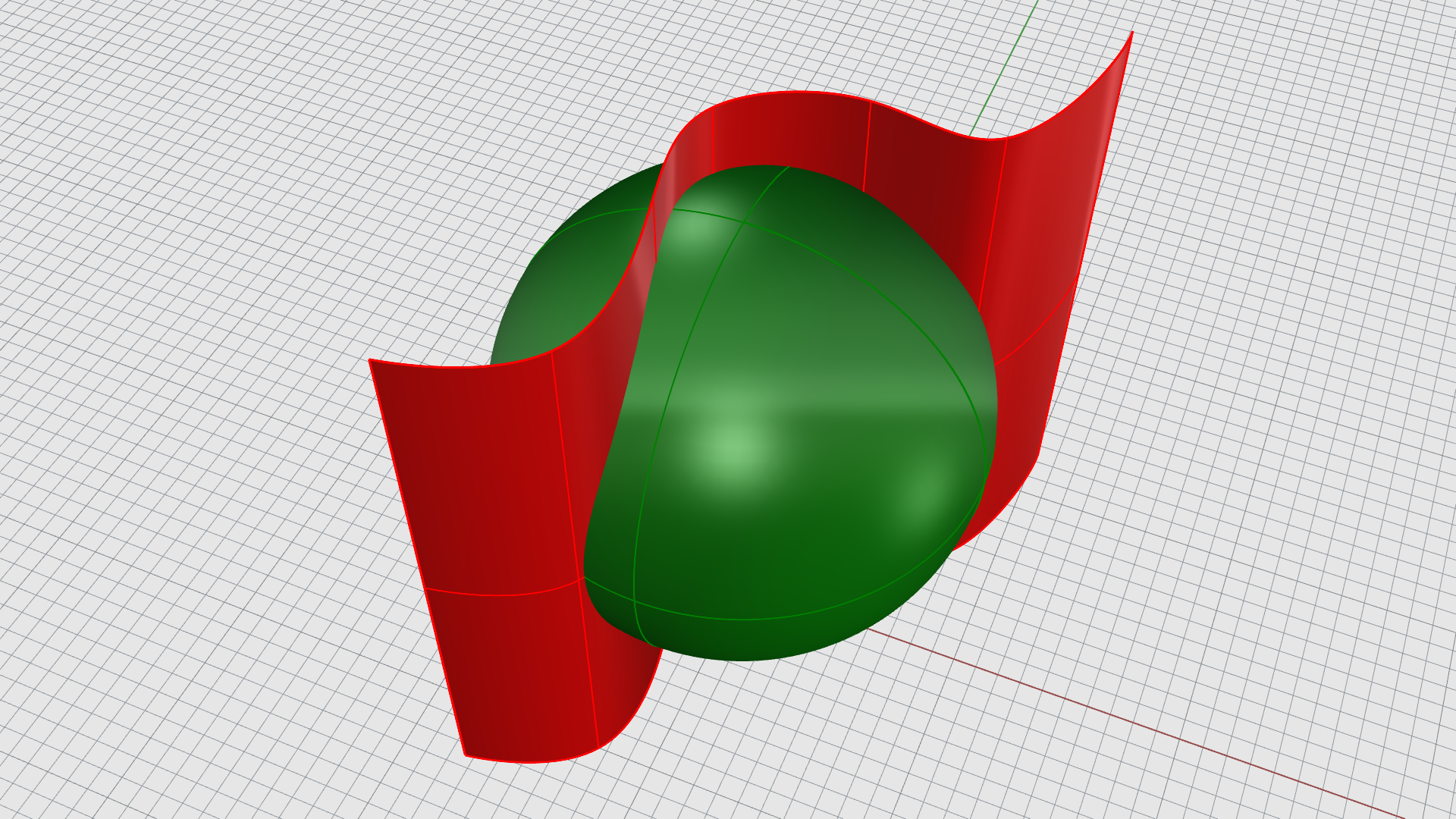
Trim Surfaces

- Run the
Trim
command.
- At the Select cutting objects prompt , select the red surface and press .
- At the Select objects to trim prompt , select the right side of the green sphere. Press .

The sphere has been cut and deleted at the intersection with the red surface.
Split
The
![]() Split
command divides objects into parts using other objects as cutters.
Split
command divides objects into parts using other objects as cutters.
Split Curves

- On the Edit menu, select the
 Split
command.
Split
command. - At the Select objects to split prompt , select the red circle and the black rectangle. Press .
- At the Select cutting objects prompt , select the blue curve. Press when done.

The red and black curves have been divided in two at the intersection with the blue curve.
Split Surfaces
- On the Edit menu, select the
Split
command.
- At the Select objects to split prompt , select the green sphere. Press .
- At the Select cutting objects prompt , select the red surface. Press when done.
The green sphere has been divided in two at the intersection with the red surface.
Untrim
The
![]() Untrim
command removes trims from a surface restoring the underlying untrimmed object.
Untrim
command removes trims from a surface restoring the underlying untrimmed object.
Untrim Surfaces

- Select the green sphere.
- Press on your keyboard to turn Control Points on.

- Run the
 Untrim
command.
Untrim
command. - At the Select edge to untrim prompt , select the edge of the inner hole. The hole is removed.
- At the Select edge to untrim prompt , select the boundary edge.

Rebuild
The
![]() Rebuild
command reconstructs curves or surfaces to a certain number of
Control Points
and Degree.
Rebuild
command reconstructs curves or surfaces to a certain number of
Control Points
and Degree.
Control Point editing is an important part of form finding. Moving control points around allows you to modify the shape of your product / project.
![]() Rebuild
allows you to adjust the number of control points as needed.
Rebuild
allows you to adjust the number of control points as needed.
Rebuild Curves
- Open Rebuild-Curve.3dm in Rhino .
- Select the black curve. Notice the control points at each end of the line.
- Select one and drag it around. The line changes direction but stays a line.
-
 Undo
the changes.
Undo
the changes. -
Select
the line again and run the
 Rebuild
command.
Rebuild
command. - In the
Rebuild
dialog box, set the: Point count to 3, Degree to 2, select Delete input. Press OK.
- Select the black curve. You’ll notice 3 control points now.
- Select the middle point and drag it. Notice how we’ve introduced a bend.

-
Rebuild
it again. This time, set the: Point count to 4, Degree to 3, select Delete input. Press OK.
Rebuild Surfaces
![]() Rebuild
works for both curves and surfaces. Surfaces have two directions called
U
and
V
. This will be reflected in the Rebuild dialog box.
Rebuild
works for both curves and surfaces. Surfaces have two directions called
U
and
V
. This will be reflected in the Rebuild dialog box.
- Open Rebuild-Surface.3dm in Rhino .
- Select Select the black surface.
- Press
on your keyboard or type the
 PointsOn
command to activate the
Control Points
.
PointsOn
command to activate the
Control Points
. - Activate the Gumball and select one Control Point .
- Move it upward. You’ll notice some stretching in the surface but not a lot of bend.
-
Undo
the move.
- Select the black surface.
- Run the
Rebuild
command.
- In the Rebuild Surface dialog box, make sure the options are as follows, and press :
( UPointCount=3 VPointCount=3 UDegree=2 VDegree=2 DeleteInput=Yes OutputLayer=Input ReTrim=Yes )
- Select the black surface and press to turn Control Points on.
- Double-click the middle control polygon to select the whole row of points.
- Drag it upward. You’ve created one bend.
- Double-click the perpendicular control polygon to select the opposite row of points.
- Drag it upward. You’ve created a dome.
