1. Introduction
The fundamental geometric objects in Rhino are points, curves, surfaces, polysurfaces, solids, lightweight extrusion objects, subdivision surfaces, and polygon mesh objects. This chapter goes into some detail to explain the mathematical basis for Rhino modeling.
This guide covers the different types of geometry supported by Rhino. Essentially, it’s the objects Rhino can read (open), create, and write (save).
Geometry Types
In this context, geometry types are different ways of representing 3D shapes in a CAD modeler using different mathematical functions. Different modelers support various geometry types. The most common ones are NURBS and meshes. There are two main advantages of supporting many different geometry types:
- Different need: Each geometry has its advantages and is easier to use to create specific shapes or use downstream for other purposes such as digital sculpting or manufacturing.
- Communicating with other programs: Importing or saving files from and to other applications supporting only a specific geometry type.
The geometry types supported in Rhino are:
- NURBS Geometry
- Subdivision Surfaces (SubD)
- Polygon Meshes
Rhino can move back and forth between its different geometry types. Some of these transformations are made easy, and others require more work.
It is the primary geometry type in Rhino, enabling high-precision freeform modeling with tight tolerances. It gives you the freeform to design while using the geometry for manufacturing. Next, we will look into NURBS object types in detail.
NURBS Geometry
NURBS (non-uniform rational B‑splines) are mathematical representations that can accurately model any shape from a simple 2D line, circle, arc, or box to the most complex 3D freeform organic surface or solid. Because of their flexibility and accuracy, NURBS models can be used in any process, from illustration and animation to manufacturing.
NURBS geometry is an industry standard for designers working in 3D where forms are free and flowing and where both form and function is important. Rhino is used in marine, aerospace, and automobile interior and exterior design. Makers of household and office appliances, furniture, medical and sports equipment, footwear, and jewelry use Rhino to create freeform shapes.
Points
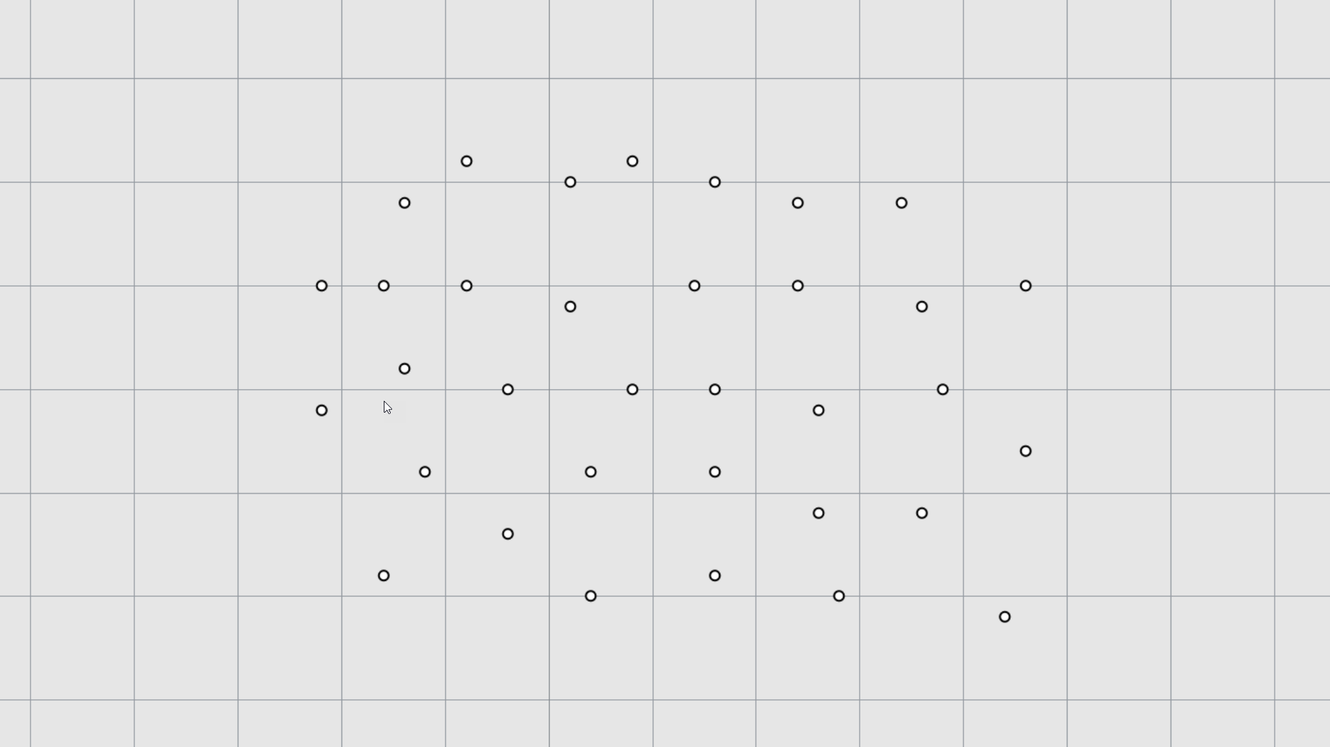
Point
objects mark a single point in 3D space. They are the simplest objects in Rhino. Points can be placed anywhere in space. They are defined by an X, Y and Z coordinate. They are most often used as placeholders. Generally, surface/mesh/SubD control points/vertices are equivalent. Use the
![]() Point
command to create this object type in Rhino.
Point
command to create this object type in Rhino.
Curves (NURBS)
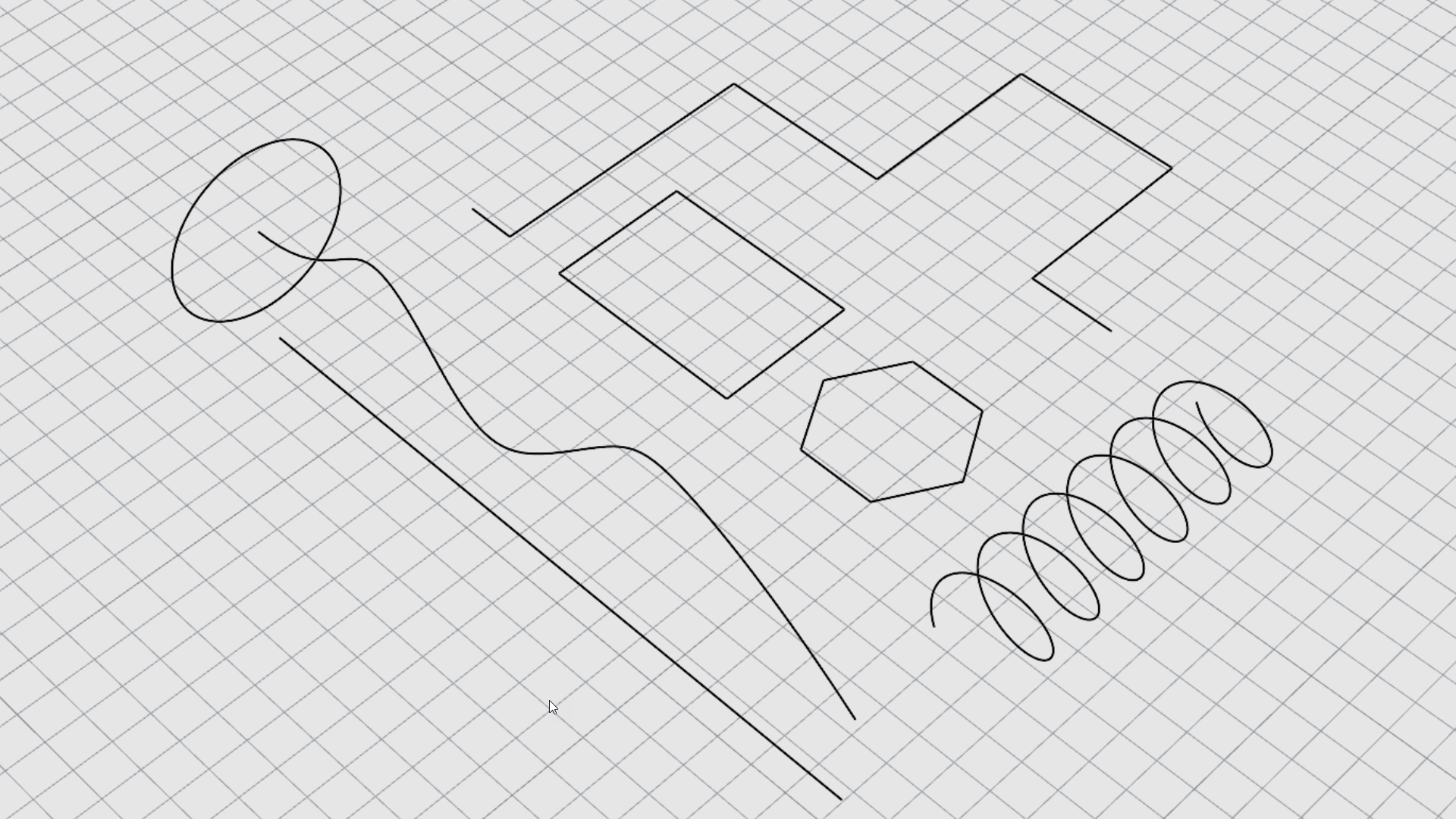
A Rhino curve is similar to a piece of wire. It can be straight or wiggled, and can be open or closed. A polycurve has several curve segments joined together end to end.
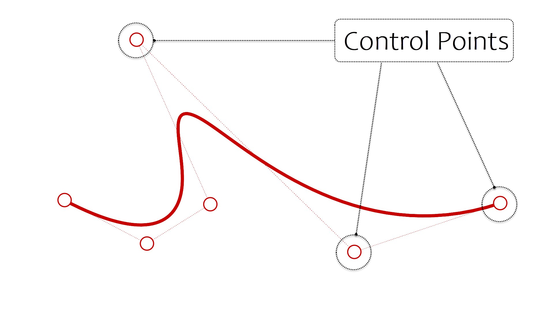
You can also draw curves using curve control points and draw curves that pass through selected points.
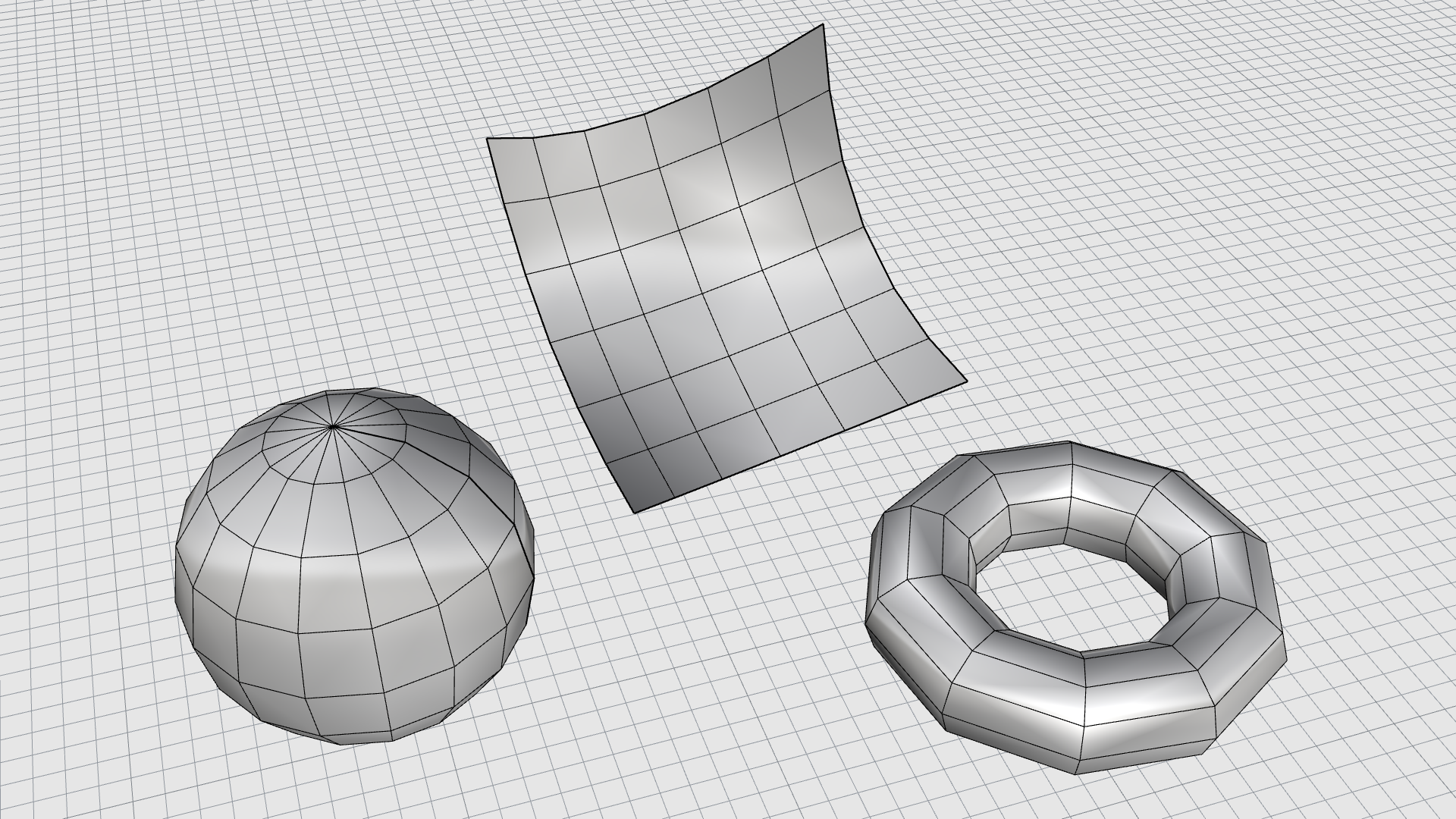
Surfaces (NURBS)
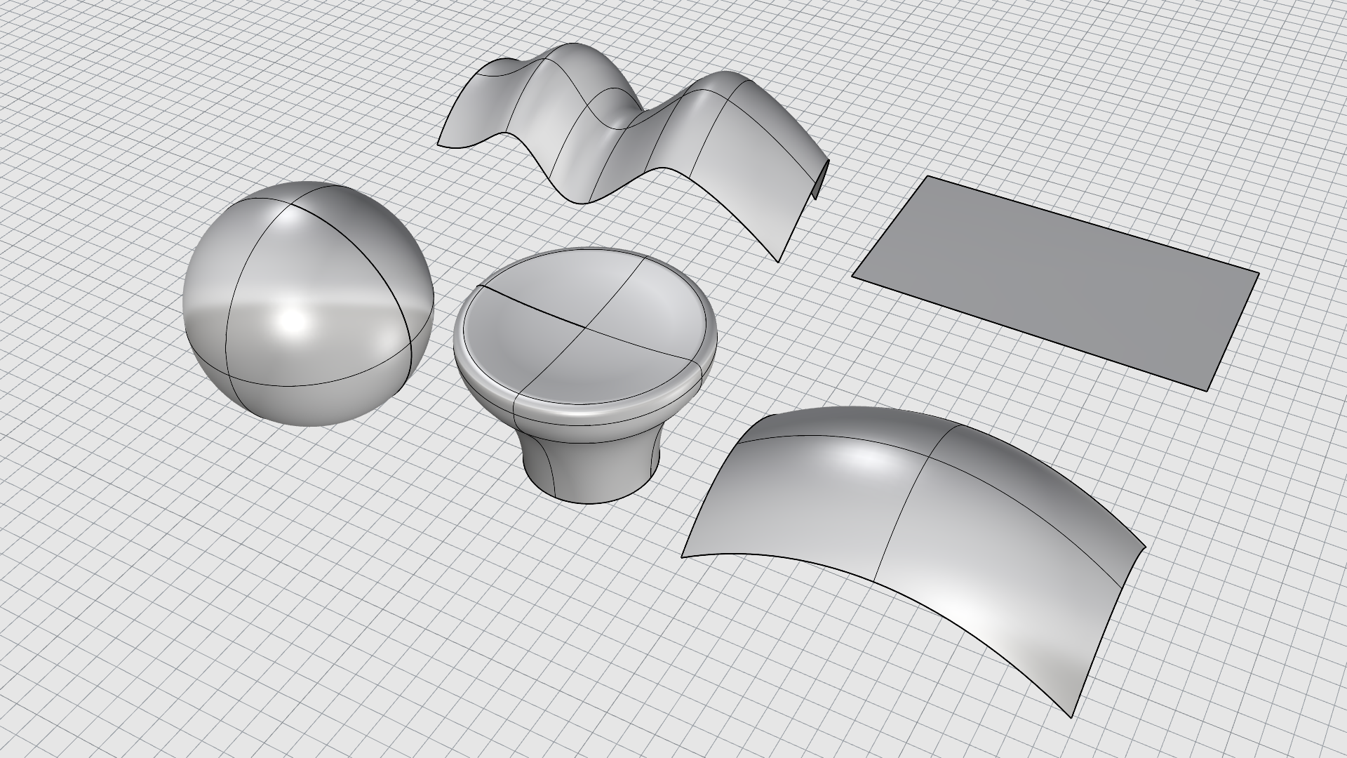
A surface is like a rectangular, stretchy rubber sheet with no thickness. The NURBS form can represent simple shapes, such as planes and cylinders, as well as free-form, sculptured surfaces. Surfaces can be open or closed. When closed, they can also be called a solid since they can calculate a volume.
There are essentially two ways of creating surfaces in Rhino:
- Start from a primitive.
- Start from existing curves.
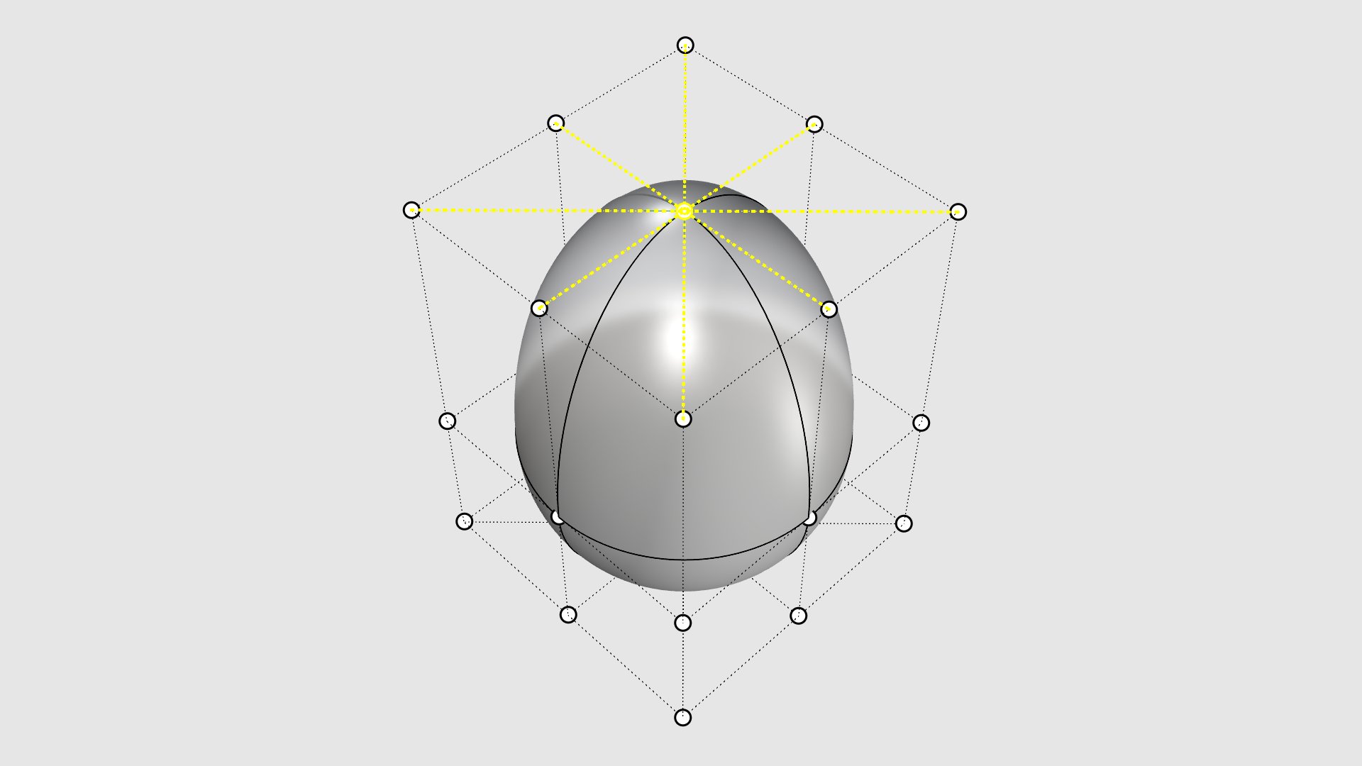
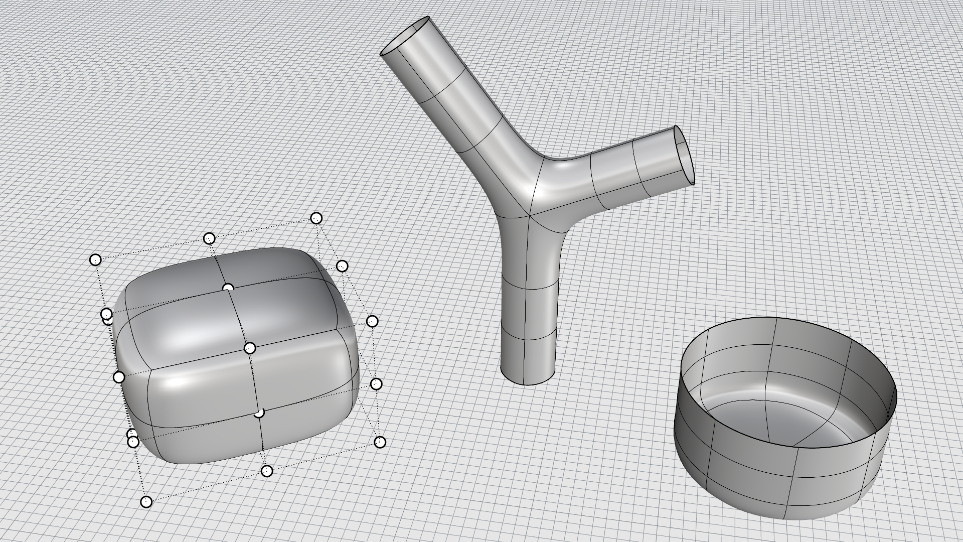
Anatomy of a Surface
Let’s talk about the visible elements of a surface. An essential part of a surface is its Control Points structure. **To visualize Control Points, select the object and press the key.
-
Control Points define the shape of a NURBS curve or surface. Most of the time, the control points don’t touch the surface. They are arranged in a grid-like pattern that holds the surface in place. Moving these control points around will change the shape of the object.
-
Isoparametric curves are a network of visible lines that go through the surface to help us understand its flow and shape in space. Commonly called isocurves. These curves help you visualize the shape of the surface. Isoparametric curves do not define the surface. They are merely a visual aid that allows you to see the surface on the screen. When a surface is selected, all of its isoparametric curves are highlighted.
-
Edge curves delimit the surface boundaries. You’ll recognize them because they are displayed slightly darker than the isocurves. In a polysurface , they define the outer boundary of each surface patch that composes the polysurface.
-
A surface seam is a special edge case of a surface of revolution or the surface resulting from the extrusion of a closed curve. Essentially, the surface of an edge that wraps around itself to close the surface where it started.
Properties of a Surface
Surface Directions
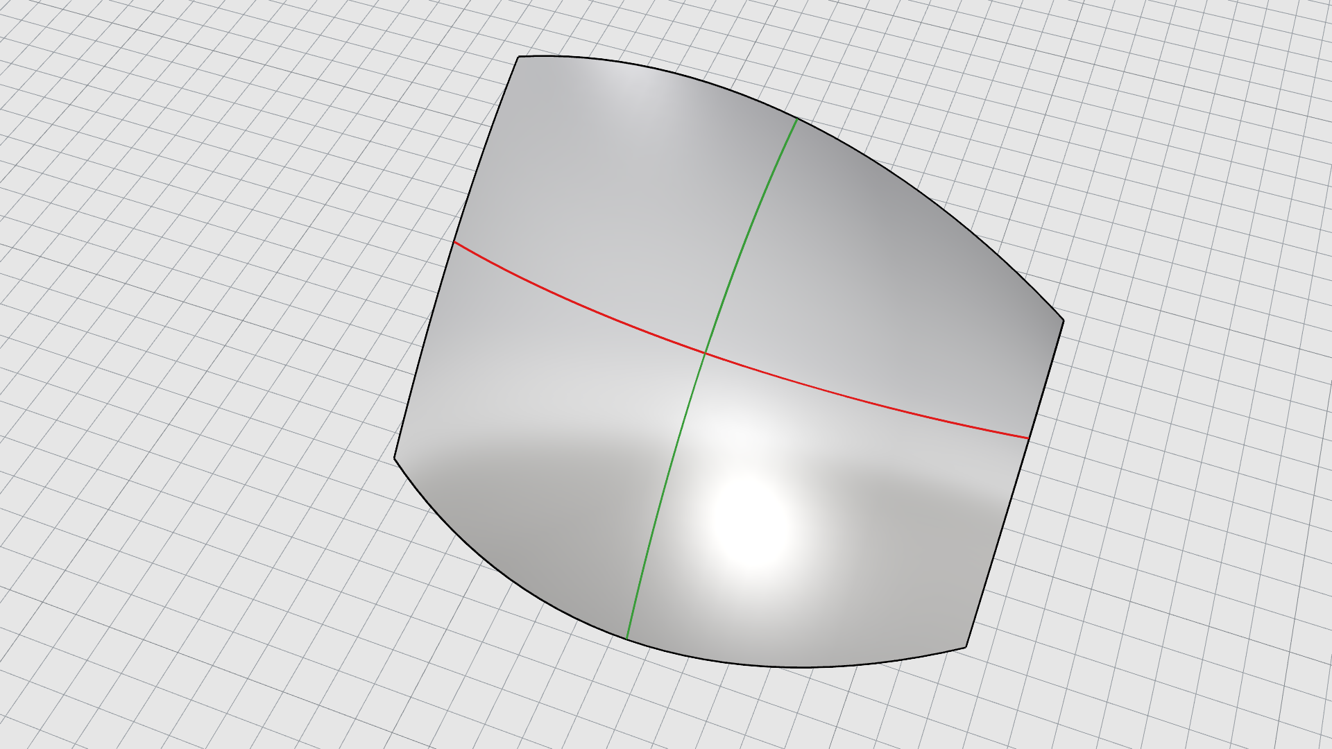
A NURBS surface has a 4-sided nature. You’ll notice this by how their Control Point structure and Isocurves are oriented. Therefore, we talk about two directions, commonly called U and V .
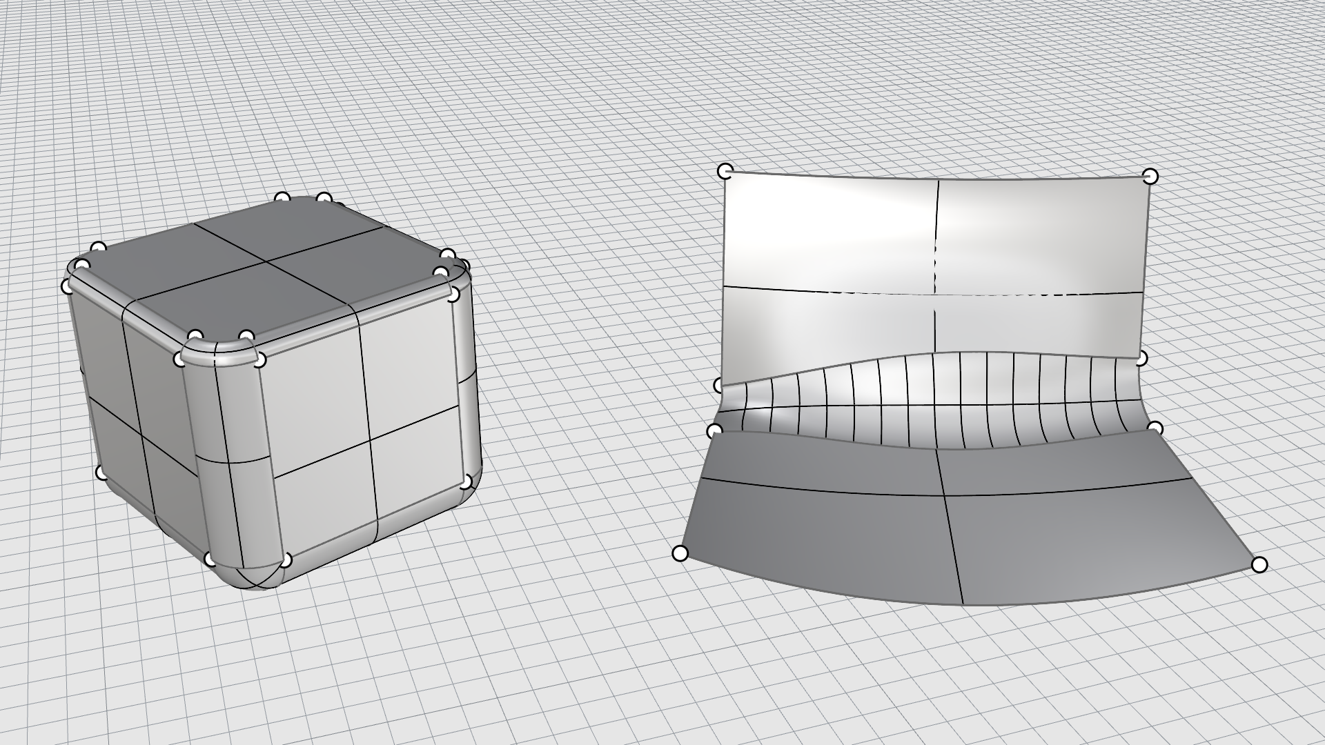
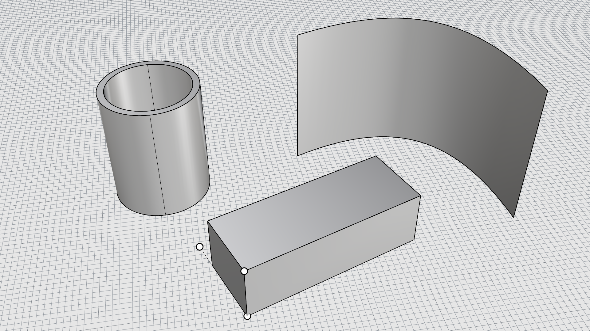
Open vs Closed Surfaces
Open Surface
Closed Surface
A surface can be open or closed. An open surface is a thin piece of geometry representing a shape, yet it has no thickness. Think of a piece of rubber or paper. You can see this surface from above and also its underside (in blue - image left). Although you cannot see the inside of a closed surface, it is a void object. Think of an inflated balloon (image right).
Untrimmed vs Trimmed Surfaces
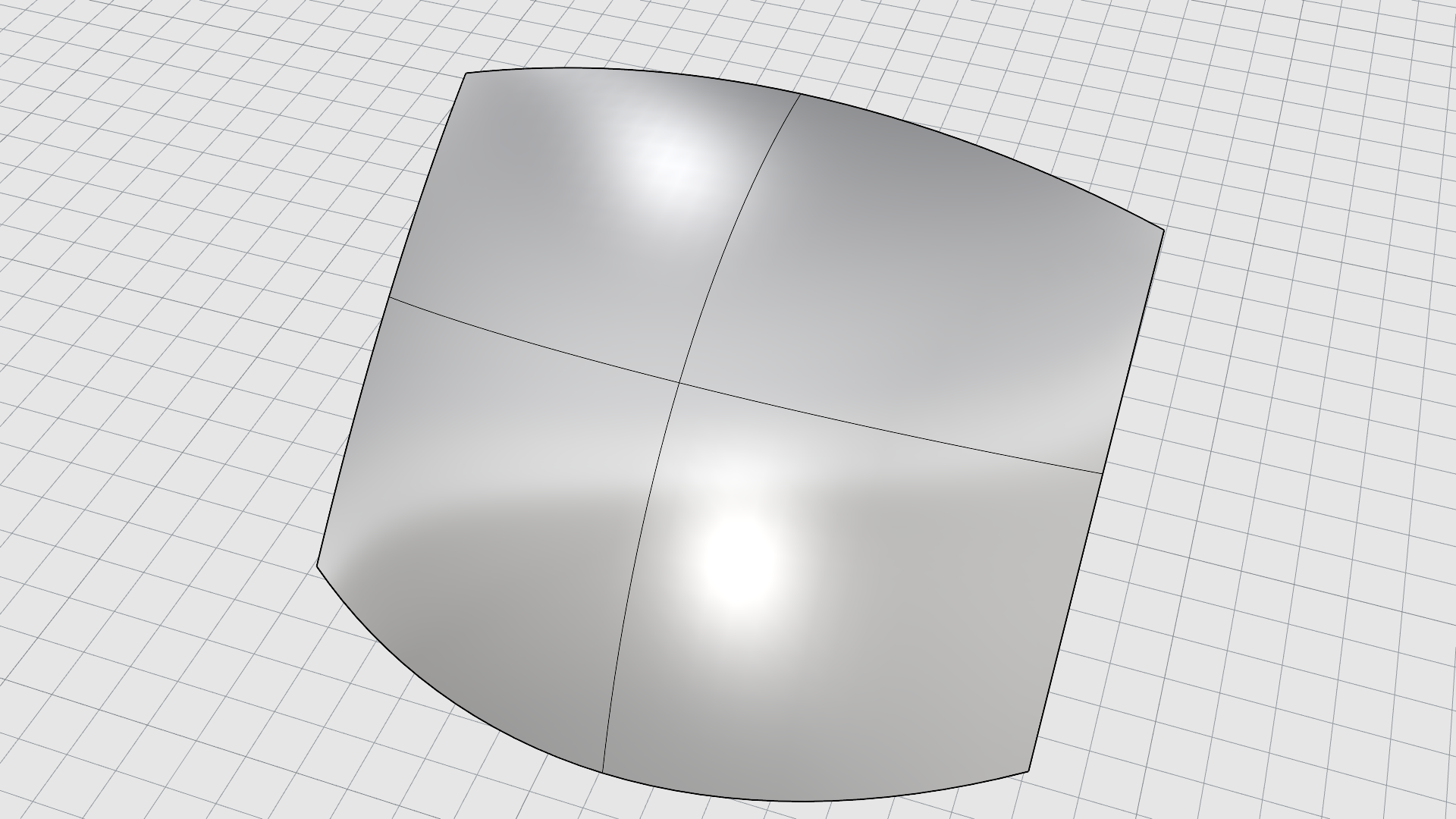
Untrimmed Surface
Trimmed Surface
Untrimmed surfaces are ones where all edges are “native”
NURBS
edges. An untrimmed surface, except for singularities, will always have four edges. These are true mathematical edges. The advantage of modeling with untrimmed surfaces is that some commands in Rhino, such as
![]() MatchSrf
or
MatchSrf
or
![]() MergeSrf
only accept untrimmed geometry.
MergeSrf
only accept untrimmed geometry.
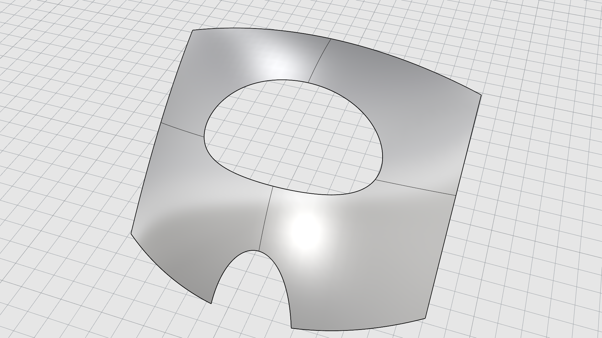
Trimmed surfaces are created when you
![]() Trim
or
Trim
or
![]() Split
a surface with a curve or another surface. Some commands, such as
Split
a surface with a curve or another surface. Some commands, such as
![]() PlanarSrf
, can create trimmed surfaces directly.
The shape of a surface is still defined by a set of
Control Points
arranged in a rectangular pattern.
PlanarSrf
, can create trimmed surfaces directly.
The shape of a surface is still defined by a set of
Control Points
arranged in a rectangular pattern.
Since it is important to know if a surface is trimmed, the
![]() Properties
command lists its trimmed or untrimmed state.
Properties
command lists its trimmed or untrimmed state.
This surface may be larger than the trimmed edge, but you will not see the underlying surface because Rhino does not draw the part of the surface that is outside the trim curves. Every trimmed surface retains information about its underlying surface geometry. You can remove the trimming boundary to recover the “native” or “natural” edges using the
![]() Untrim
command.
Untrim
command.
If you have a trimming curve that runs across a surface, the trimming curve itself does not have any real relationship to the control point structure of the surface. You can see this if you select a trimmed surface and turn its control points on (select it and press ). You will see the control points for the whole underlying surface.
Singularity
A singularity is an edge that is collapsed into a single point. Often surfaces formed by revolving a curve around an axis have singularities at the revolve axis. Think of the poles of a sphere.
Degree (Curve or Surface)
Four things define NURBS geometry:
- Degree
- Control Points
- Knots
- Evaluation Rule
NURBS functions are rational polynomials. The degree of the NURBS is the degree of the polynomial. A polynomial is a function like y = 3x3 –2x +1. The “degree” of the polynomial is the largest power of the variable. For example, the degree of 3x3 –2x + 1 is 3; the degree of –x5 + x2 is 5, and so on.
From a NURBS modeling point of view, the (degree –1) is the maximum number of “bends” you can get in each span. This determines how much you can affect the shape of the curve.
For example:
-
A line has degree 1. It has two control points. It has zero bends.
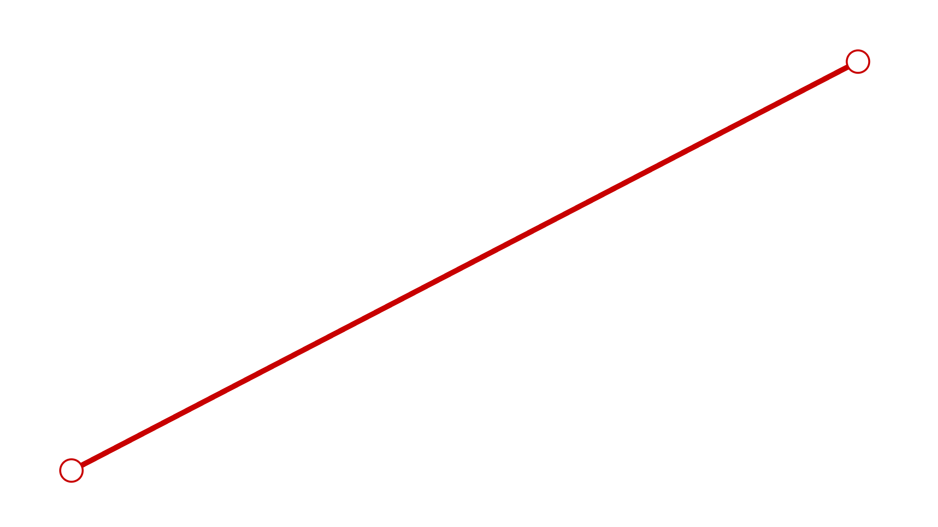
-
A parabola, hyperbola, arc, and circle (conic section curves) have degree 2. They have three control points. They have one bend.
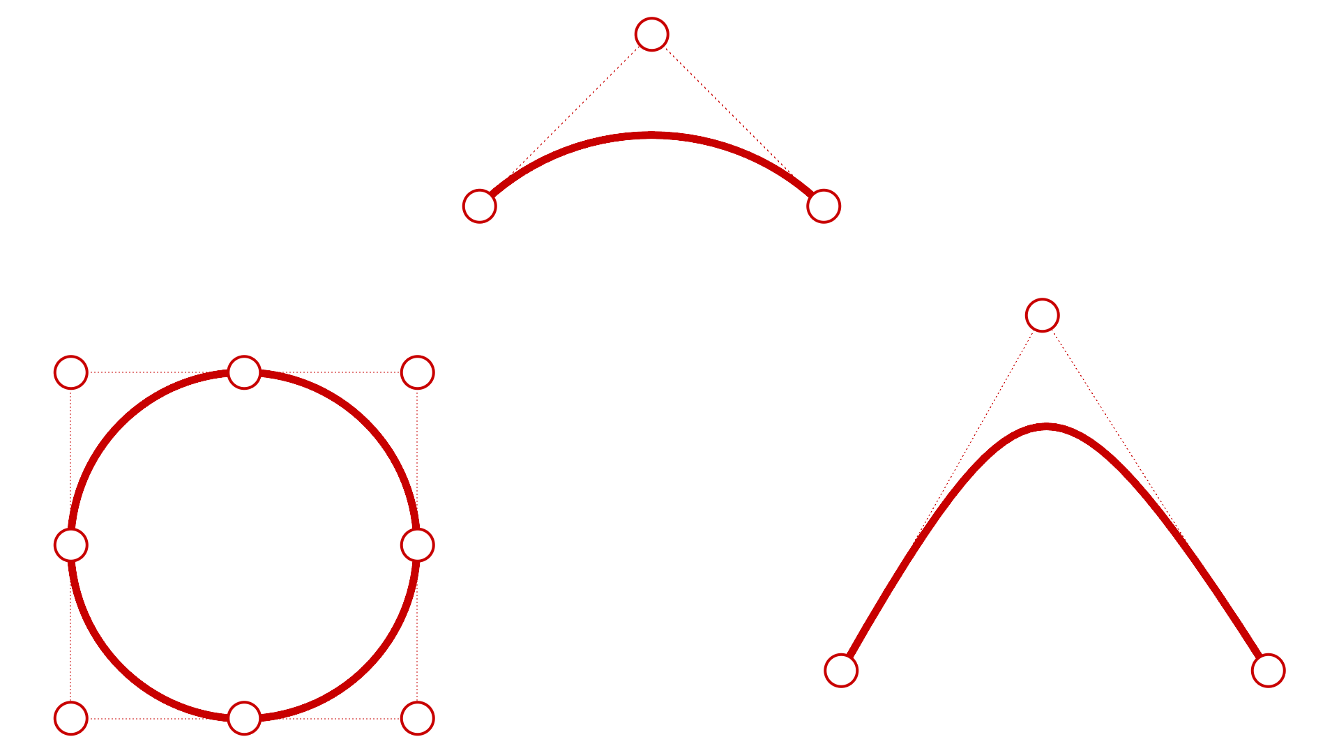
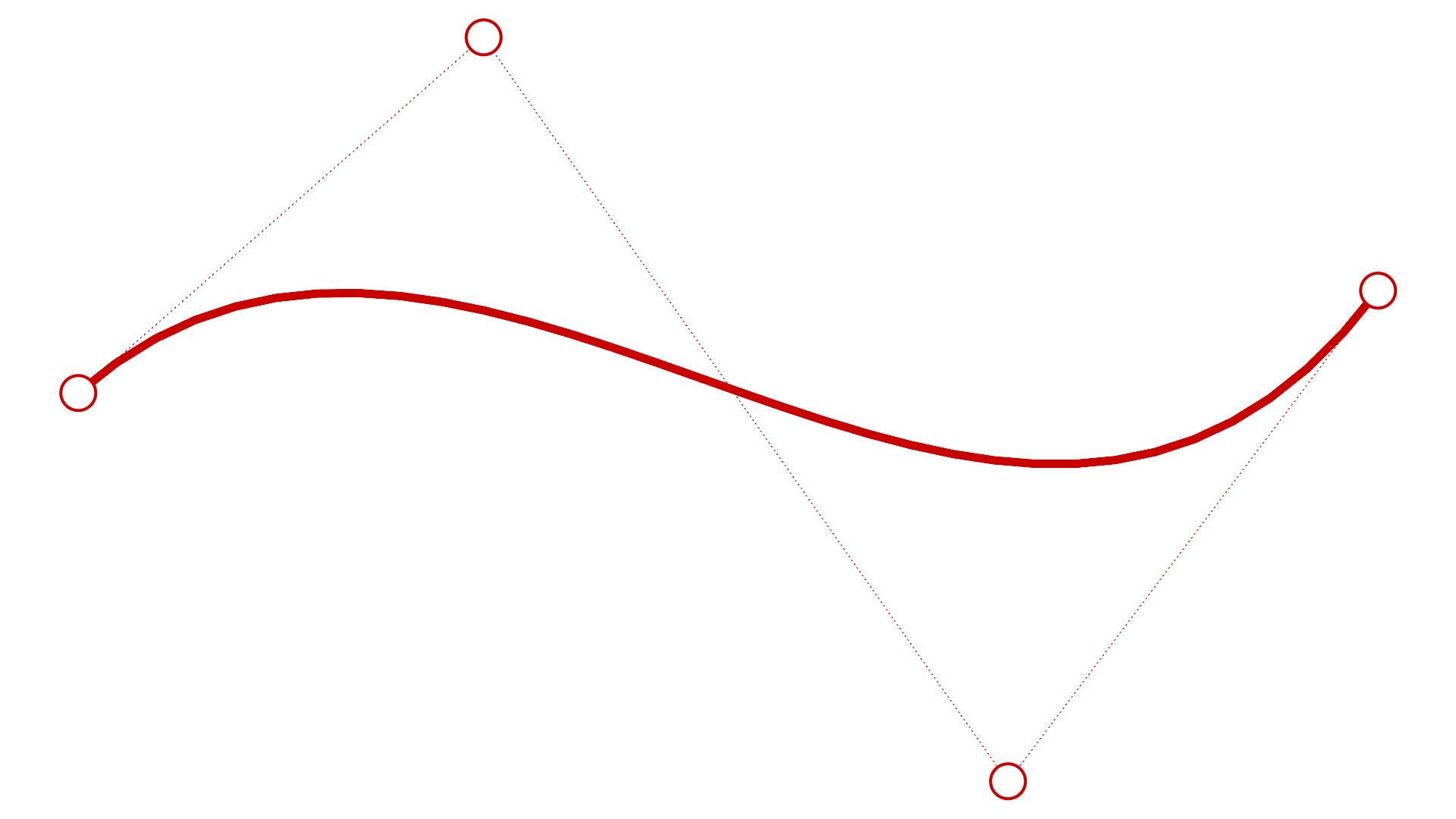
-
A cubic Bézier has degree 3. If you arrange its control points in a zigzag shape, you can get two bends.
Control Points
Control points influence the shape of a curve or surface. The control point holds such information as location, direction, and weight. You can make subtle changes in the curve or surface shape by moving the location of its control points. Rhino offers many tools for editing control points. Some of the later tutorials show control point manipulation.
When you move control points, the curve or surface changes and Rhino smoothly redraws it. Rhino’s transform commands, such as
![]() Move
,
Move
,
![]() Copy
,
Copy
,
![]() Rotate
and
Rotate
and
![]() Scale
can manipulate individual or multiple points.
Scale
can manipulate individual or multiple points.
Polysurfaces (NURBS)
A Polysurface consists of two or more surfaces that are joined together. A polysurface that encloses a volume of space defines a solid.
The
![]() SolidPtOn
command turns on grip points that act like control points for polysurfaces. However, editing these points should be constrained to a linear direction to keep the object’s structure intact.
SolidPtOn
command turns on grip points that act like control points for polysurfaces. However, editing these points should be constrained to a linear direction to keep the object’s structure intact.
Solids
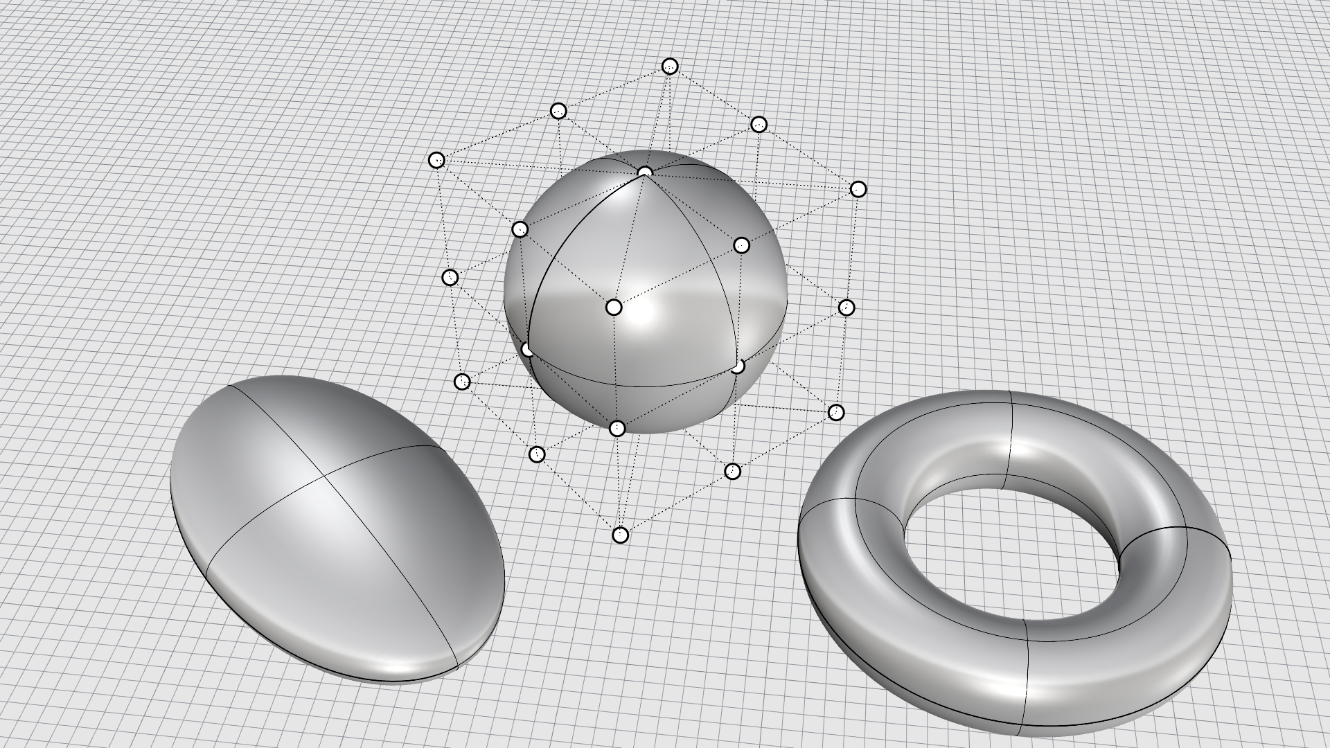
A solid is a surface or polysurface that encloses a volume. Solids are created anytime a surface or polysurface is completely closed. Rhino creates single-surface solids, polysurface solids, extrusion solids, mesh solids, and SubD solids.
A single surface can wrap around and join itself. Example commands include
![]() Sphere
,
Sphere
,
![]() Torus
and
Torus
and
![]() Ellipsoid
.
Control Points
can be displayed on single-surface solids and moved to change the surface.
Ellipsoid
.
Control Points
can be displayed on single-surface solids and moved to change the surface.
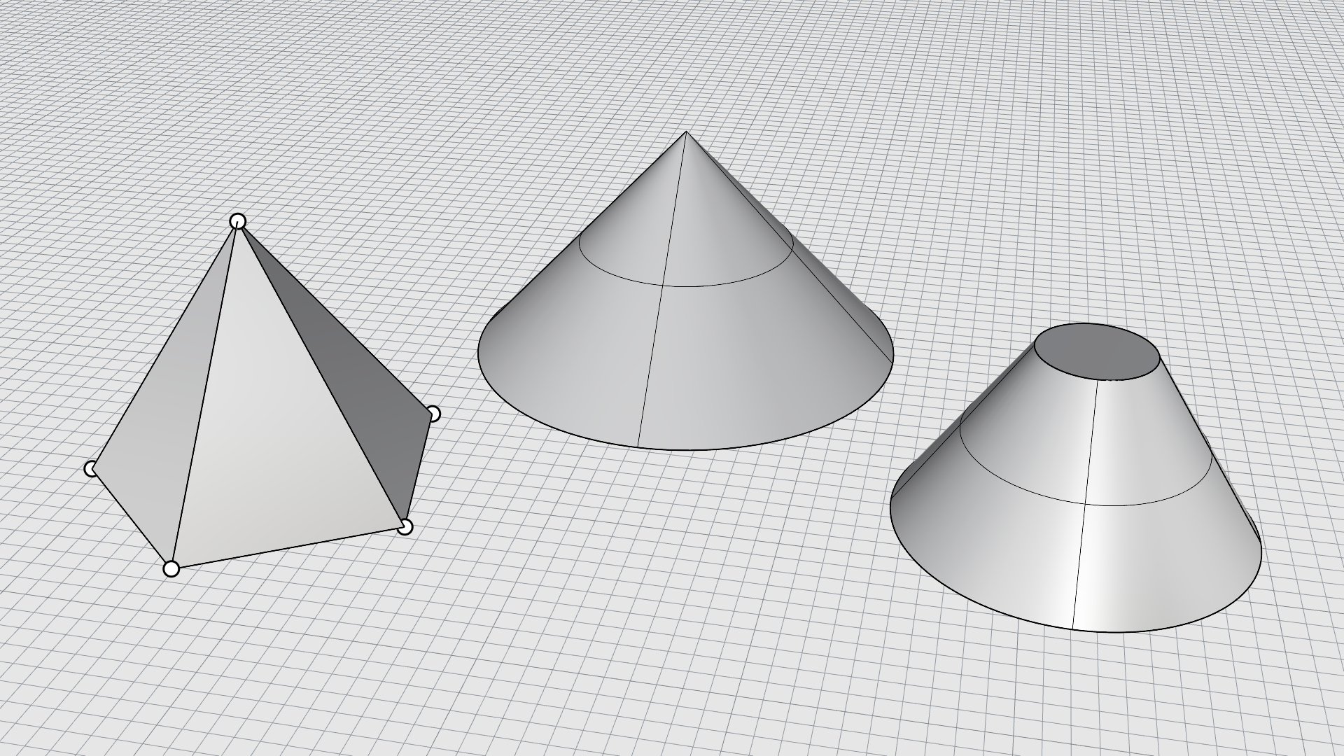
Some Rhino commands create polysurface solids.
![]() Pyramid
,
Pyramid
,
![]() Cone
and
Cone
and
![]() TruncatedCone
are examples of commands that create polysurface solids.
TruncatedCone
are examples of commands that create polysurface solids.
SubD Geometry
Rhino SubD Objects are high-precision Catmull-Clark subdivision surfaces designed to model and edit complex organic shapes quickly.
SubDs in Rhino are composed of vertices, edges, and faces. You can push or pull on these to shape the object. Think of SubD as clay material.
Mesh Geometry
A mesh is a collection of vertices and polygons that define the shape of a polyhedral object. Meshes in Rhino consist of triangles and quadrilaterals. Just like NURBS , meshes can be open or closed (solid).
Many programs use polygon meshes to represent geometry for rendering, animation, digital manufacturing, visualization, and finite element analysis. The
![]() Mesh
command translates
NURBS
geometry into polygon meshes. Rhino can read and write many mesh format files. To draw mesh objects, use commands such as
Mesh
command translates
NURBS
geometry into polygon meshes. Rhino can read and write many mesh format files. To draw mesh objects, use commands such as
![]() MeshSphere
,
MeshSphere
,
![]() MeshBox
,
MeshBox
,
![]() MeshCylinder
.
MeshCylinder
.
In addition, Rhino has commands that allow you to work with mesh.
Lightweight Extrusions
Lightweight Extrusions
use only a profile curve and a length as input instead of the network of curves normally needed for
NURBS
objects. The
![]() Box
,
Box
,
![]() Cylinder
,
Cylinder
,
![]() Tube
and
Tube
and
![]() ExtrudeCrv
commands create extrusion objects. Extrusion objects can be closed with a planar cap or open.
ExtrudeCrv
commands create extrusion objects. Extrusion objects can be closed with a planar cap or open.
If necessary, these objects will be converted to polysurfaces by some commands to add additional information for editing. Use the
![]() PointsOn
command or press
to turn on Extrusion points.
PointsOn
command or press
to turn on Extrusion points.
