This topic discusses a collection of topological problems, which may render a particular shape invalid under certain circumstances. In this context, topology refers to the fundamental interconnectedness of vertices, edges, loops and faces, which together make up a shape. The topology does not include issues such as zero-length curves, zero-area faces, NaN-coordinates or self-intersections, which are all types of geometric faults.
This topic will use a labeling scheme with different symbol categories for different topological classes. Vertices will be identified by Arabic numerals , edges by Latinate lower-case letters , loops by Greek letters and faces by Latinate capital letters .
All entities apart from vertices can be imagined as an ordered list of references to other entities. For example, edges are defined by the two vertices at their start and end points, loops are defined as chains of consecutive edges, and faces are defined by a set of loops—one outer boundary loop and any additional loops representing holes and slits.
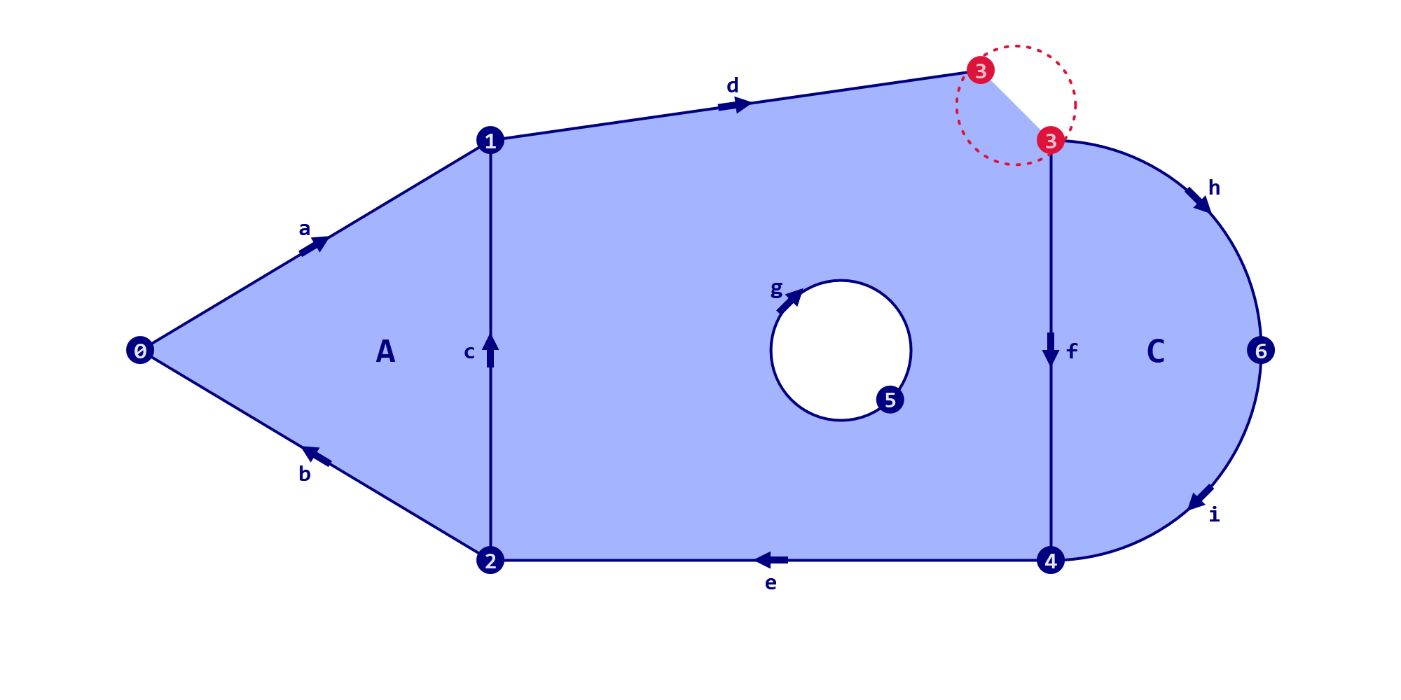
Thus a fully specified edge might be denoted as h(3,6), telling us that edge h starts at vertex 3 and terminates at vertex 6. In a similar vein, describes a loop named which consists of the edges h, i, and f, with the added complication that within the loop the f edge is reversed from its intrinsic direction, hence the additional inversion symbol.
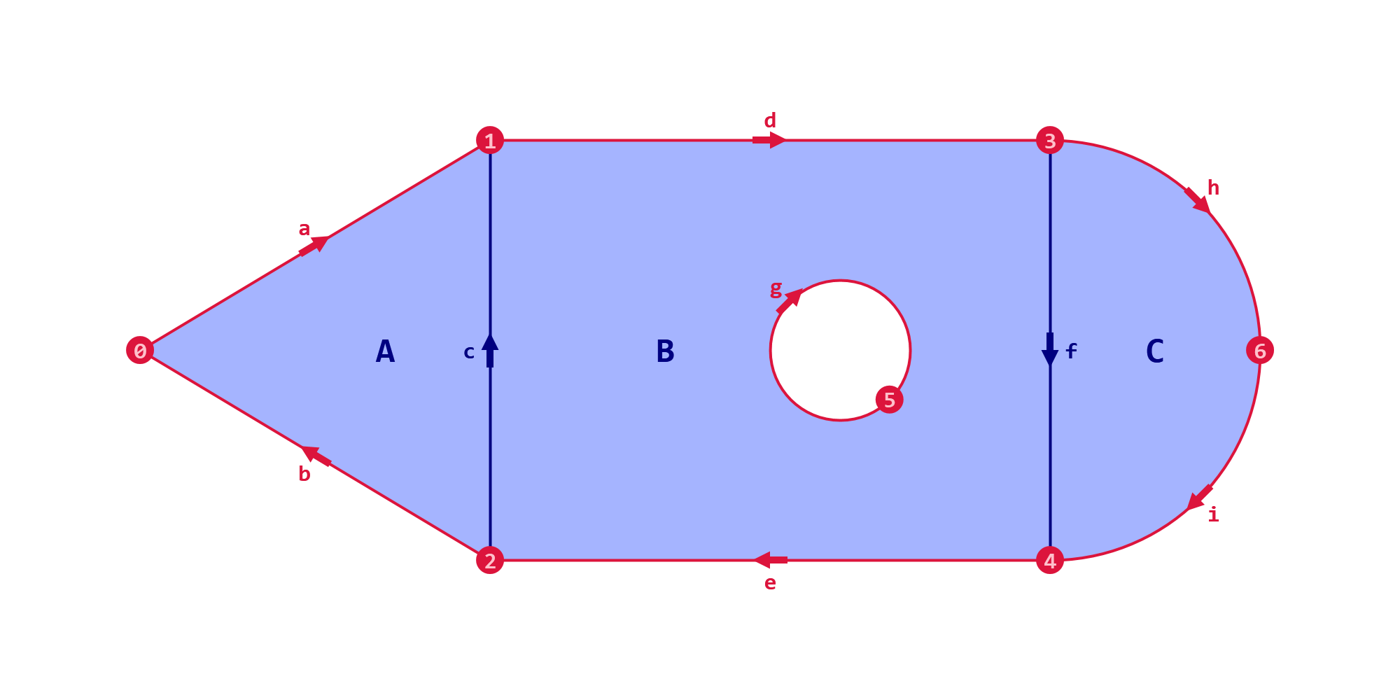
Putting all this together, we can draw a topological diagram of a valid shape consisting of three faces, four loops, nine edges and seven vertices, as shown in Figure 1.
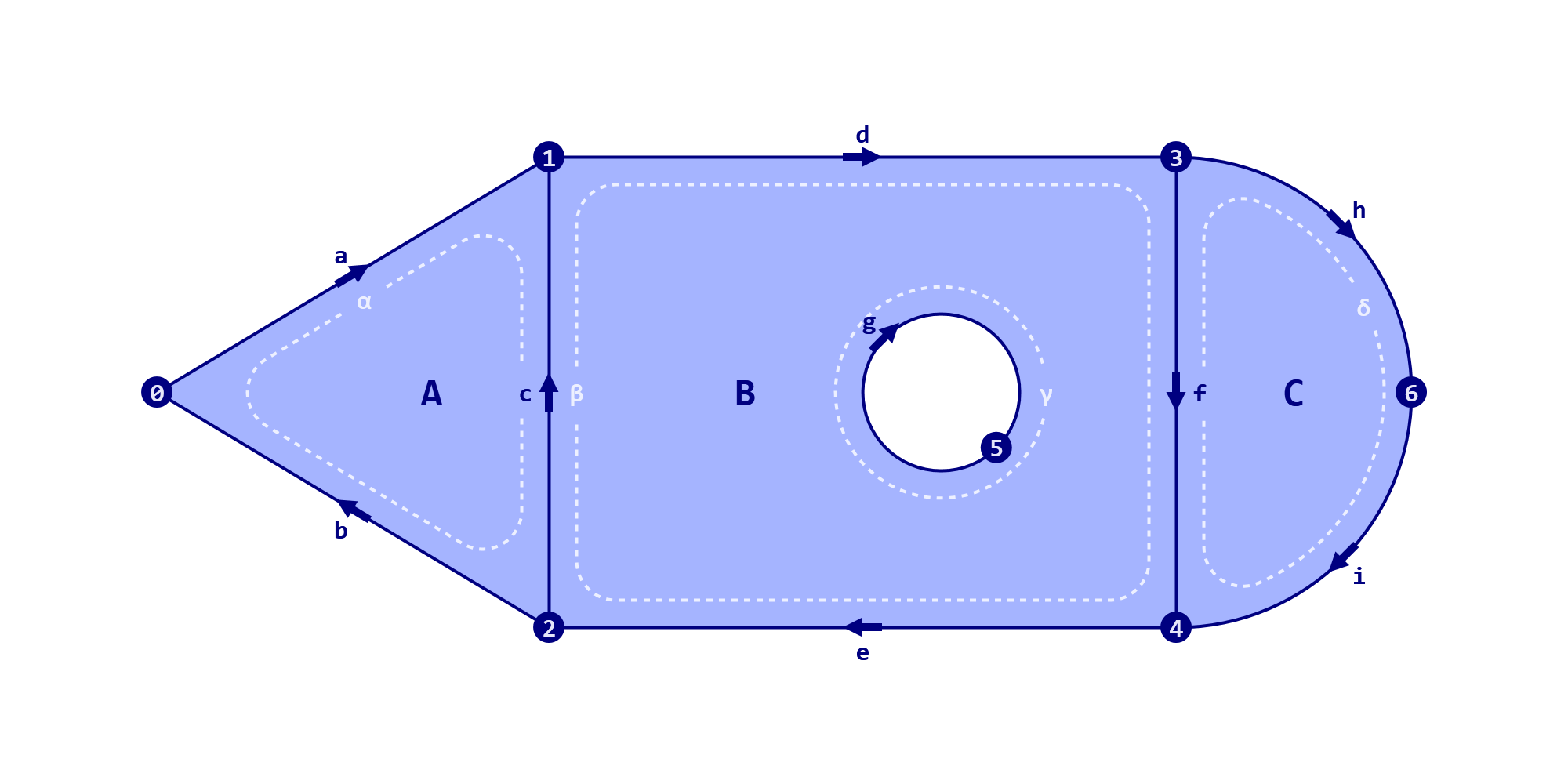
The full topological connectivity of this shape looks like this:
| Entity | Indices |
|---|---|
| Vertices | (0, 1, 2, 3, 4, 5, 6) |
| Edges | a(0,1)b(2,0)c(2,1)d(1,3)e(4,2)f(3,4)g(5,5)h(3,6)i(6,4) |
| Loops | |
| Faces |
Take a moment to convince yourself that the table and Figure 1 indeed describe the same underlying shape.
There are many changes we can make to this specification without changing the geometry of the shape, or indeed without invalidating its topology. Edges can be reversed, vertices re-ordered, and loop seams cycled, to name just a few possible transformations. As long as the connected entities change in unison, a valid topology is maintained.
Yet, as the title implies, there are also many ways in which a topological specification can be faulty. Sometimes these defects are easy to detect and repair, at other times a shape may be beyond salvation. It is even possible for a particular defect to be irrelevant in one context, but prohibitive in another. This topic merely aims to list as many problem categories as one is likely to encounter, along with the associated nomenclature.
Do keep in mind that the scheme of (vertices, edges, loops, faces) adopted here is not universal. Oftentimes the topology of a shape is defined with fewer or different kinds of entities. In Rhinoceros and Grasshopper alone there are differences between mesh and brep topologies. In meshes the edges and loops are implicit, as faces directly reference into the vertex collection. Meanwhile breps add more edge types into the mix in order to maintain both three-dimensional (x,y,z) edges and two-dimensional (u,v) trimming curves.
For current purposes however, our system will suffice to demonstrate the various fault categories.
Indexing Faults
The first defect category we will discuss concerns the indexing of non-existent instances. Indexing means indicating a connection between entities and may also be referred to as "referencing" or "linking" or "pairing". As previously stated, edges can be written as , where and identify specific vertices. If one or both of those vertices are not available then the edge cannot be valid. Similarly, a loop which references a non-existent edge, or a face referencing a non-existent loop also both fall into the indexing fault category.
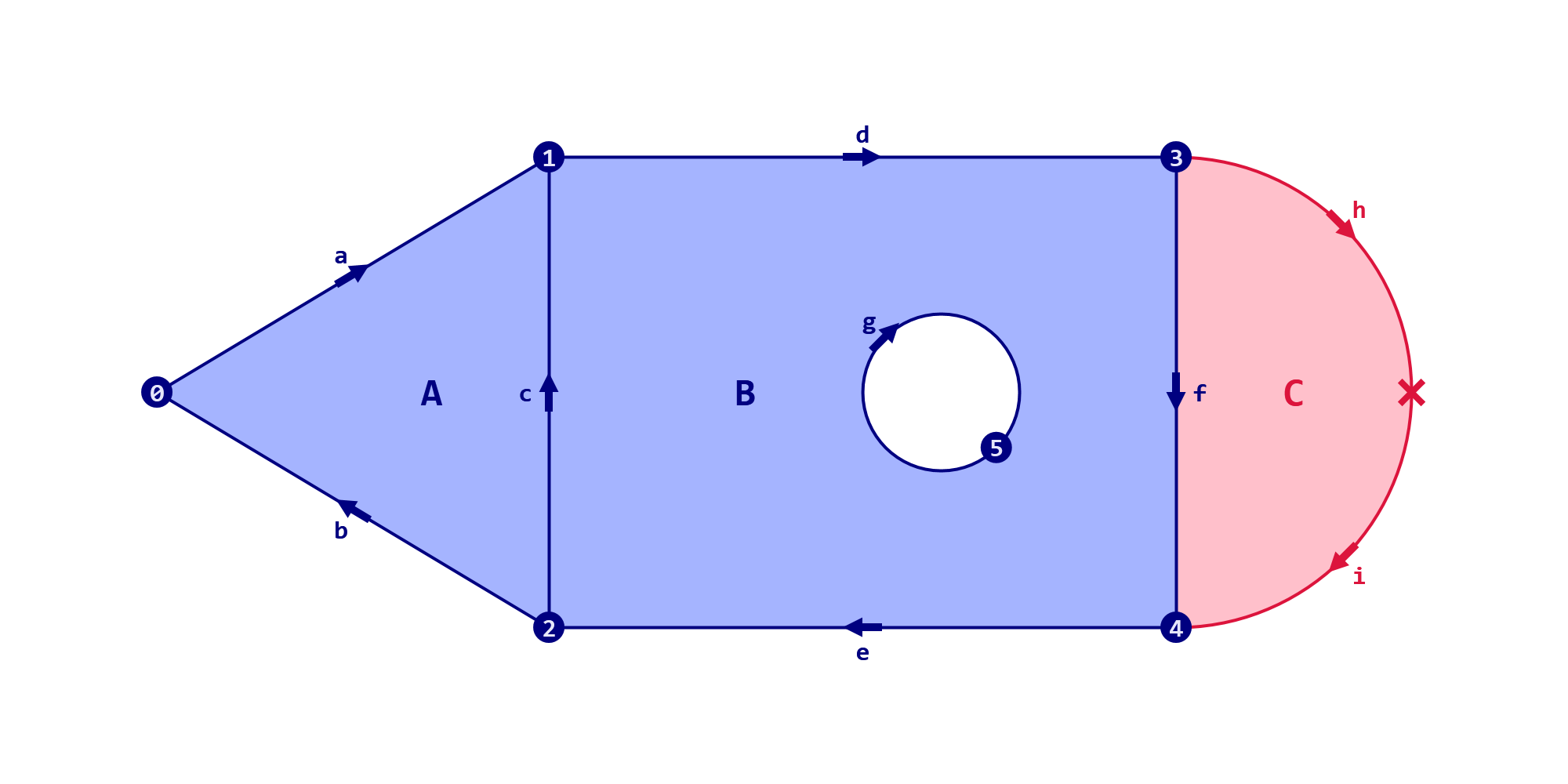
The most common way for indexing faults to arise is the removal of entities from the shape, combined with an incorrect update procedure. For example, imagine we deleted vertex 6 from our topology as per Figure 2, but forgot to also delete the edges, loops and faces reliant on that vertex (to wit: h, i, , and C). This would leave us with a connection graph with two edges that have become unmoored at one end:
If instead of the last vertex we chose to delete the first one, we would end up in an even bigger mess. The removal of vertex 0 means all remaining vertices are shifted backwards on the list, so what used to be vertex 3 is now vertex 2. Not only do we still get an indexing fault —vertex 6 has become vertex 5—, but all the edges now connect the wrong points in space. Every edge, loop and face is now either invalid, or hopelessly spatially mangled.
Deleting elements from a topology, especially several elements at once, is a tricky operation to get right. Reference indices need to be adjusted and reliant entities need to be removed, which triggers yet more changes to the remainder of the shape.
Redundancy Faults
In a sense, redundancy is the exact opposite of an indexing fault. Instead of an entity trying to reference a non-existent value, the topology contains values which are not referenced at all by the other entities. Whether this is actually a problem, depends heavily on context. For example, Rhinoceros will happily allow a mesh to contain any number of unused vertices without marking the mesh as invalid. The Rhinoceros _MeshRepair command will report them, and other commands such as _Extrude may remove these vertices, but they are unlikely to cause any problems.
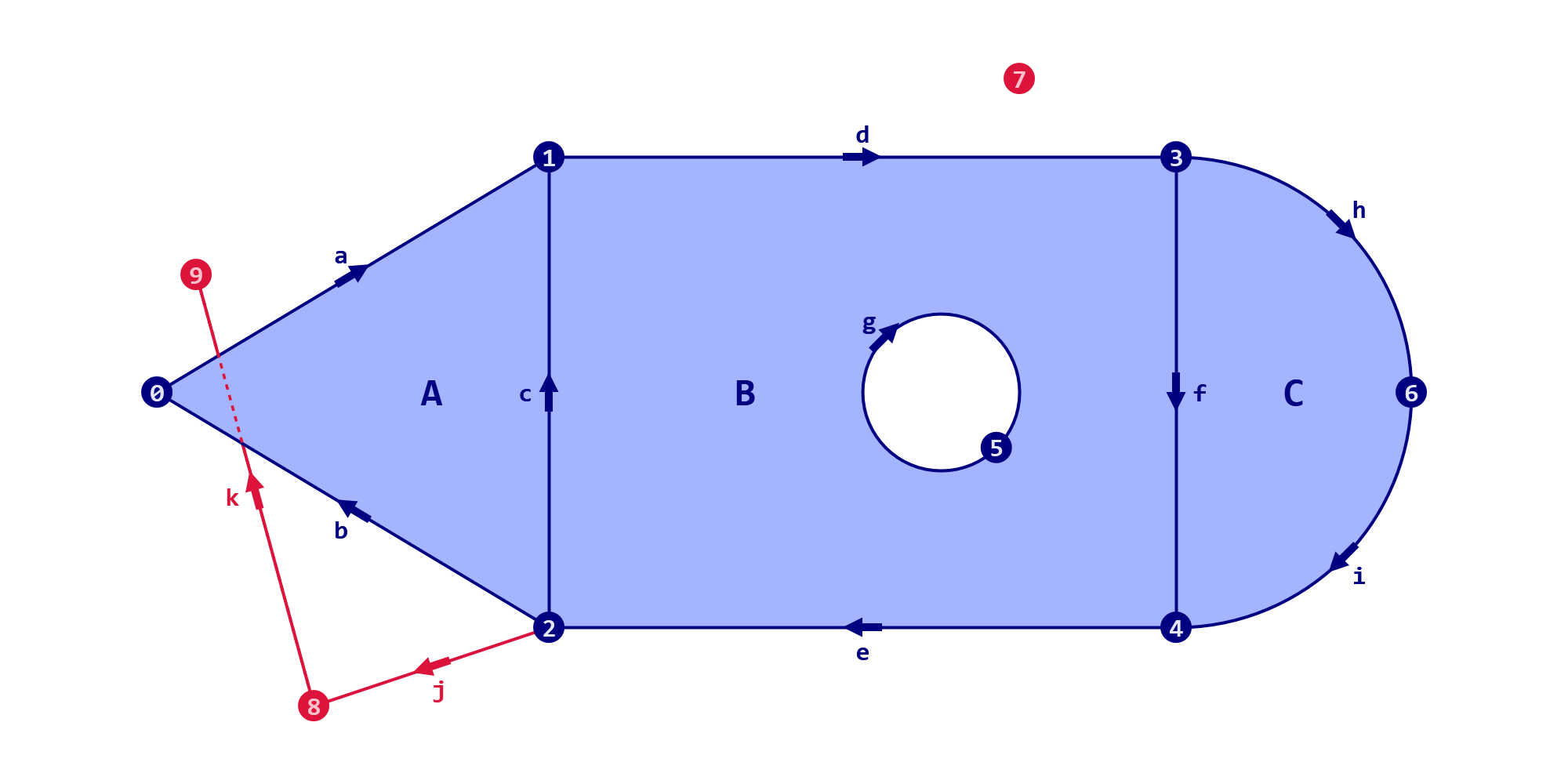
Figure 3 shows a topology with three redundant vertices (7,8,9), and two redundant edges (j,k). If the context permits loose edges to exist, then the only superfluous entity in this topology is vertex 7.
Depending on the type of geometry involved, different redundant entities may or may not cause problems. Breps for example do not allow unused vertices or edges. In general breps are more finicky about their topological correctness. However, almost all modifications to a brep are handled entirely by Rhinoceros core code and as such any flaws are almost certainly the responsibility of some Robert McNeel & Associates developer rather than the user.
Naked Edges
A very common topological property, which is nevertheless invalid in certain contexts, is the occurrence of naked edges. If the modelling context requires the shape to have a computable volume or a consistent interior/exterior evaluation, then naked edges will be considered a defect. This is the case for example in 3D-printing or cnc-milling processes.
Naked edges occur when an edge is indexed by only a single loop, and they can arise entirely naturally. However, it is possible to limit oneself to a subset of modelling operations and foundational shapes which guarantee that at any time during the modelling process every edge is indexed by exactly two loops. This approach is usually called solid modelling.
Fixing naked edges is topologically trivial, but geometrically very difficult. All that is required to make a topology solid is to collect all nakes edges, join them into closed loops -which is always possible- and create faces bounded by those loops.
In Figure 4 all edges are naked except for c and f. We can create a new loop , and two new faces and as per Figure 5. This new topology no longer suffers from naked edges, but it is only a partial solution to the problem. After all, the geometric shapes of these two new faces must also be defined and that is not at all an obvious task.
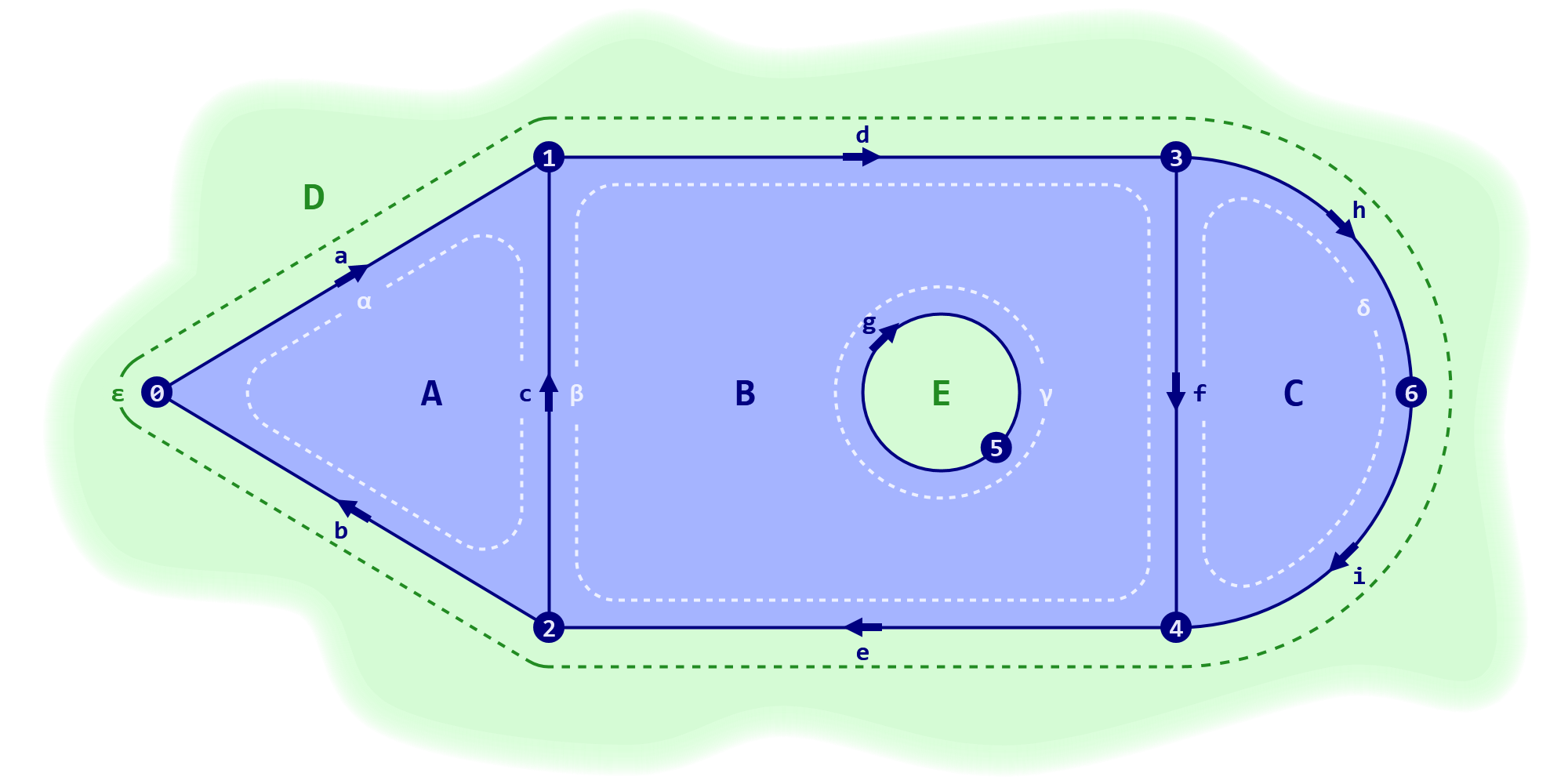
In certain special cases straightforward solutions do present themselves. For example, if the loop geometry is planar, a fairly simple surface shape is implied directly by the boundary loop. In this case the surface would be just a flat plane In Rhinoceros and Grasshopper this planar special case operation is called capping.
Non-Manifold Edges
Edges indexed by zero, one or two loops are classified as redundant, naked and interior respectively. Any edge which is part of more than two loops, however, is non-manifold and almost always a severe topological fault. Figure 6 shows how edge c becomes non-manifold by adding a third face called D.
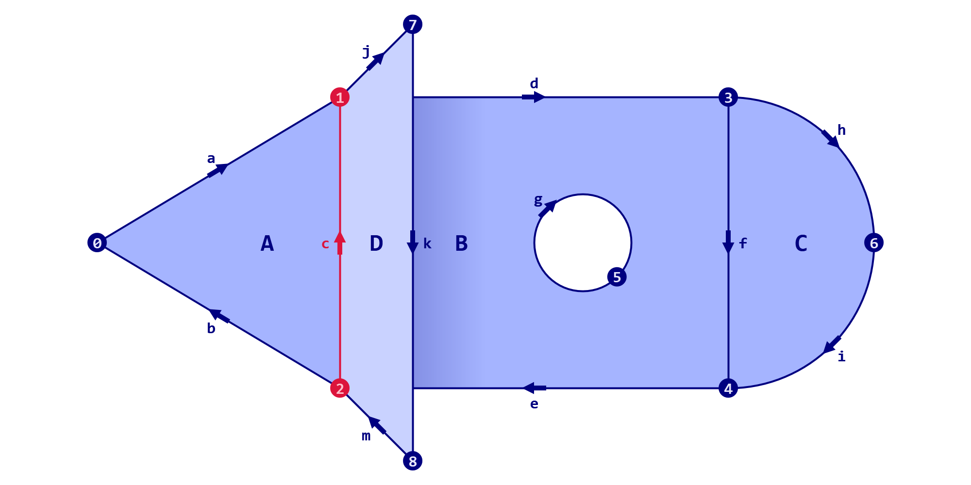
The problem with non-manifold edges is that they interfere both with the notion of volume and the consistent orientation. When two faces meet along an edge and love each other very much, their normal directions can typically be aligned so that their fronts and backs are on the same side. Although note that this may not be possible for all edges in a shape simultaneously, more on this in the section on non-orientability. When three or more faces meet along the same edge, at least two of them will always have opposing normal directions.
Repairing non-manifold defects can be easy or difficult, depending on the specifics of the case at hand. Sometimes an easily identifiable rogue face can just be removed from a shape, at other times it can be difficult or even impossible to determine which face or group of contiguous faces is the undesired entity.
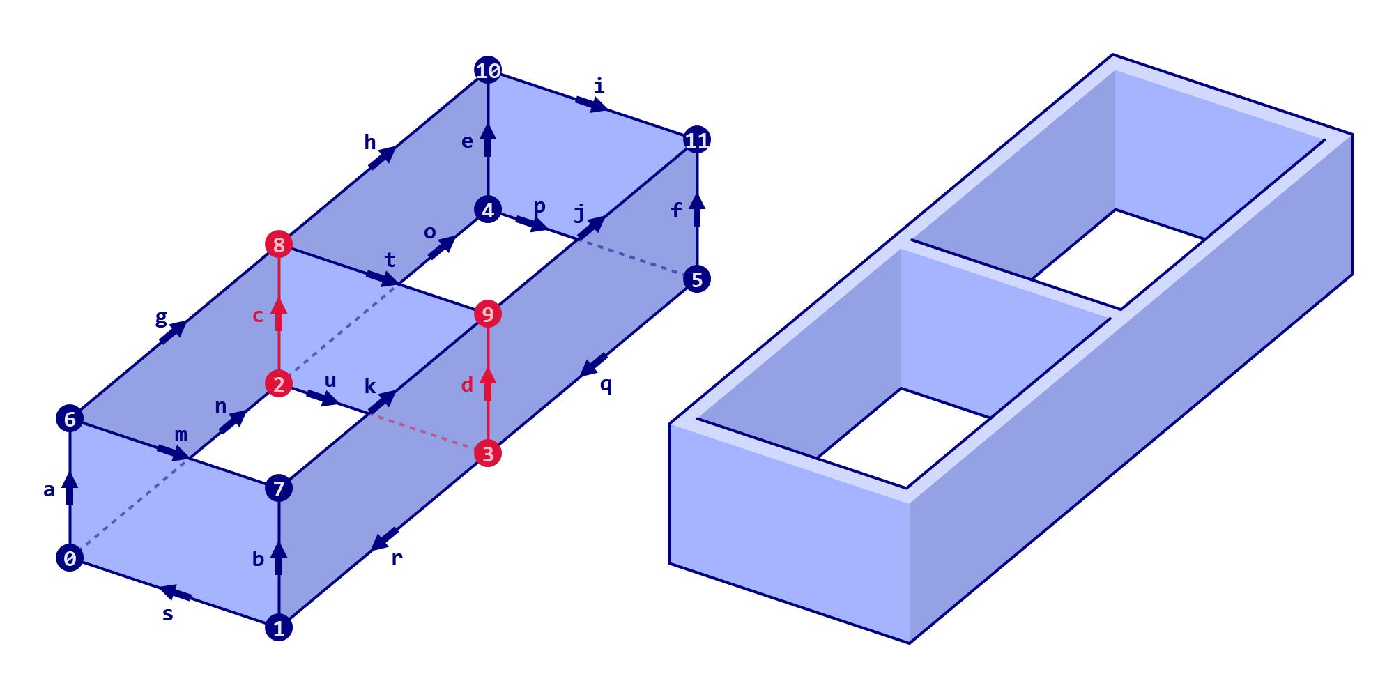
In some situations a non-manifold topology can be valid. This is obviously the case in abstract mathematics, but it may occur with physical models as well. For example if a structure consists of thin plate elements joined together, it may make sense to initially not model the elements as volumetric shapes, but only as their centre-planes, leaving the thickening step to a later stage in the modelling process, as per Figure 7. Thickening always removes all naked and non-manifold edges, thus yielding a solid topology.
Duplicate Indexing
Loops and faces are collections of one or more indexed entities —edges and loops respectively— and both place various constraints on the entities, which, when broken, invalidate the topology. One constraint shared amongst both types is that an entity may only be indexed once. If the central face of our main example were to be defined as it might not look any different geometrically, but it would be an invalid shape.
Meshes in Rhinoceros are an exception to this rule. As previously mentioned, they do not contain edges or loops as integral parts of their topologies. Instead, faces cut out the middleman and index the vertices directly. Furthermore each face stores exactly four vertex indices which means each mesh face wants to be a quad. However sometimes we need mesh faces to be triangles instead, and this is accomplished by indexing the third vertex twice. I.e. a mesh face which is defined as A(0,3,7,23) represents a quadrilateral, whereas a face defined as B(1,4,9,9) is a triangle connecting vertices 1, 4, and 9.
Hence, a Rhinoceros mesh face allows a specific kind of duplicate indexing without becoming invalid. However, any other duplication, for example C(2,5,9,2) or D(3,9,9,14), breaks a valid topology. Such a fault is fairly easily fixed just by moving the duplicates to the end of the list though.
If a mesh face contains more than two, or two groups of two duplicates, it cannot be repaired. For example E(4,7,7,7), F(5,5,5,5) or G(6,6,8,8) would be examples of degenerate faces. It is trivial to remove all degenerate faces from a mesh at least, without affecting the shape, since these faces always have zero area.
Open Loops
A constraint placed on the chain of edges making up a loop is that all edges must be coincident with their immediate neighbours on both sides. Two edges whose end points do not meet ought not be joined together as part of a loop.
Yet Rhinoceros does allow small gaps between edges, provided they are coincident within document tolerance. These small faults can be papered over since the tweaking required to rectify the problem should be invisible due to being smaller than the granularity of the model, as specified by the document tolerance setting. Unfortunately these small and ignorable issues can become large and prohibitive when the shape is scaled up.
Inconsistent Edge Direction
A special case of open loops arises when an edge is coincident with both its neighbours, but not at the expected end points. The start of an edge must be coincident with the end of the previous edge, while the end of an edge must be coincident with the start of the next edge.
It is not always possible to reverse the direction of an edge if it is the wrong way around since two loops which both index a single edge may require it to travel in opposite directions. Because of this, a loop is not merely an ordered list of edge indices, but it must also specify for each edge whether its direction within the loop is intrinsic or reversed.
A mistake in the direction flags will produce orientation faults. Luckily, these too are typically easily detected and repaired.
Inconsistent Loop Orientation
As previously mentioned, the intrinsic direction of edges can be counter to the constraints imposed on them via loop membership, which is why individual edges may need to be reversed. There is an analogy here with loop orientation, which can also be in one of two states; clockwise and anti-clockwise.
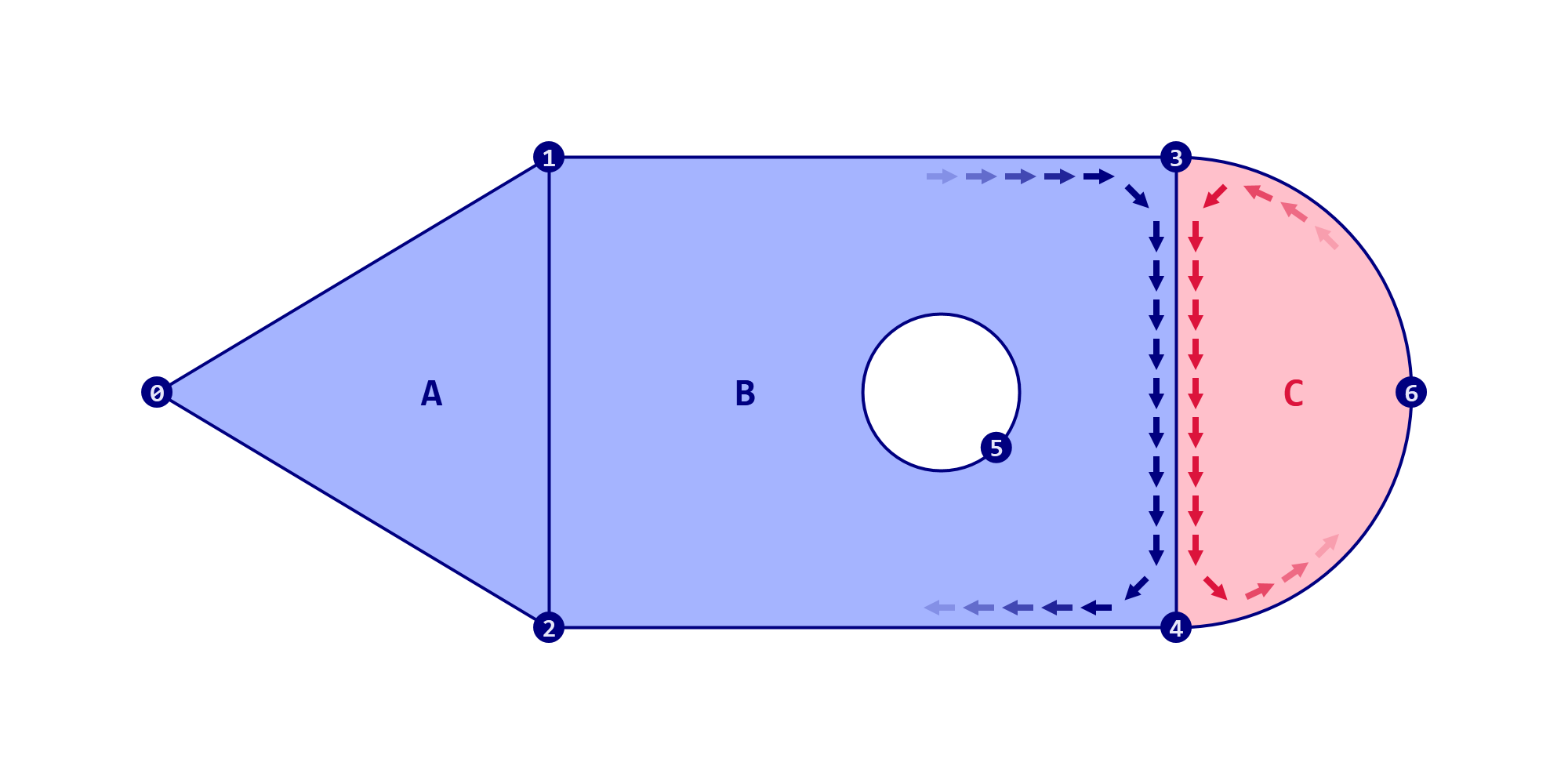
In certain contexts it may be important for adjacent faces or loops to have consistent orientations, i.e. they are all clockwise or anti-clockwise. For this to be true, the edges shared amongst both must always be traversed in opposite directions. In our example, this means that either loop or loop must reverse the direction of their shared edge c, and either loop or loop must reverse edge f. Since both these demands are met, the example topology has consistent orientation.
If however we were to reformulate the third loop as as per Figure 9, it’s orientation becomes anti-clockwise and counter to . Note that neither loop is invalid individually, the defect occurs at their interaction.
Generally speaking, orientation matters in meshes, but not in breps.
Non-Orientable Faces
As discussed in the section on non-manifold topologies, faces with opposite normal directions along their shared edges may be problematic. When three faces meet at a single edge, two of them will always have opposite normals, but it is also possible for two faces to have opposite normals in a way which cannot be remedied. A non-orientable shape is intrinsically twisted in such a way that there must always be an edge somewhere on it where two faces with opposing normals meet. The most famous examples of such shapes are the Möbius strip, the Klein bottle and the Cross-cap.
Conclusion
Topological faults come in a wide variety of types, some simple and some complicated. Faults can be serious or trivial depending on context. Yet in almost all cases faults are easier to avoid than to repair.