![]()
Extract Mesh > Extract connected mesh faces
![]()
Mesh > Mesh Edit Tools > Extract > Connected
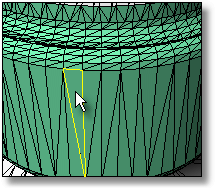
Separates from the parent mesh those faces connected to a selected face where the angle between the connected faces is within defined limits.
This command helps clean up and repair mesh files for rapid prototype printing.
The ExtractConnectedMeshFaces command extracts a set of faces from a joined mesh based at a break angle. This can be used to extract a series of faces that make up a planar surface in a mesh or to extract set of faces that make up a coherent feature in the mesh.
Steps:
Select a mesh face.
Adjust options to get the selection you want.
Click OK to extract the selected mesh faces.
Options
Angle between faces
Sets the angle between faces for selection.
A setting of 0 will give you all the faces that are connected and planar with the face you pick.
Sometimes planar meshes have a little noise in them, so a angle of 1 can help select planar faces.
Greater than
At angles greater than the Angle between faces value.
Less than
At angles less than the Angle between faces value.
Select Faces
Select two faces to specify the angle you want.
Border only
Creates a polyline around the selected area.
Edit Selection button
Click to select a different mesh face.
|
Extract Mesh > Extract connected mesh faces
Mesh > Mesh Edit Tools > Extract > Connected |
Separates identical faces in a single mesh from the parent mesh.
This command helps clean up and repair mesh files for rapid prototype printing.
Steps:
Select a mesh object.
|
Extract Mesh > Extract duplicate mesh faces
Mesh > Mesh Edit Tools > Extract > Duplicate |
Separates faces from the parent mesh determined by a draft angle or weld status.
This command helps clean up and repair mesh files for rapid prototype printing.
Steps:
Select a mesh.
Options
Extract edges by
Unwelded
Draftangle
Select edge ___ Greater than
Select edge ___ Less than
|
Extract Mesh > Extract mesh edges
None |
Separates selected faces from the parent mesh.
This command helps clean up and repair mesh files for rapid prototype printing.
This command works best in shaded mode, because you can pick the shaded faces as well as the face edges.
Steps:
Select a mesh face
|
Extract Mesh > Extract mesh faces
Mesh > Mesh Edit Tools > Extract > Faces |
Separates faces from the parent mesh that are within a specified range of area.
This command helps clean up and repair mesh files for rapid prototype printing.
Steps:
Select a mesh.
Options
Faces greater than
Selects faces with an area greater than the specified setting.
Faces less than
Selects faces with an area less than the specified setting.
Select Face
Select a mesh face to set the value to compare.
Select range from face
Sets the area by picking an example face. A range of ±10% of the area of the selected face is used.
|
Extract Mesh > Extract mesh faces by area
Mesh > Mesh Edit Tools > Extract > By Area |
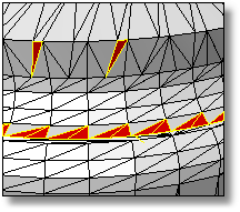
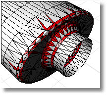
Separates faces from the parent mesh that are greater than the specified aspect ratio limit.
This command helps clean up and repair mesh files for rapid prototype printing.
ExtractMeshFacesByAspectRatio is good for finding mesh faces that are very long compared to their width. A ratio of 25:1 or above is considered long.
In the image, the extracted red faces have an aspect ratio of 9:1 or more.
Steps:
Select a mesh.
Options
Aspect Ratio
Set the target aspect ratio.
Select Aspect Ratio From Face
Select a mesh face to specify the Aspect Ratio value.
|
Extract Mesh > Extract mesh faces by aspect ratio
Mesh > Mesh Edit Tools > Extract > By Aspect Ratio |
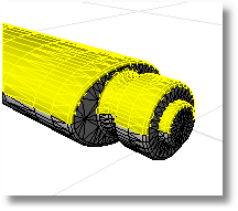
Separates faces from the parent mesh based on the angle of the faces to the view.
This command helps clean up and repair mesh files for rapid prototype printing.
ExtractMeshFacesByDraftAngle works well for splitting a mesh object for molds or to look for undercut areas. In the example, the mesh faces were selected in the top view.
Steps:
Select a mesh
Options
Start angle from camera direction
Set the starting angle from the direction of the viewport camera.
End angle from camera direction
Set the ending angle from the direction of the viewport camera.
Border only
Creates a polyline at the borders of the selected faces.
Update To View
If the view is changed, click this button to update the selection.
|
Extract Mesh > Extract mesh faces by draft angle
Mesh > Mesh Edit Tools > Extract > By Draft Angle |
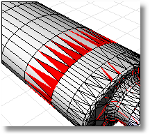
Separates faces from the parent mesh that have an edge length greater or less than a specified value.
This command helps clean up and repair mesh files for rapid prototype printing.
ExtractMeshFacesByEdgeLength is good for removing small or large faces that do not belong in the mesh.
In the example image, the extracted red faces have an edge length shorter than 0.1.
Steps:
Select a mesh.
Options
Edge Length
Sets the edge length to compare.
If GreaterThan, selects faces with an edge length greater than the Edge Length setting.
If LessThan, selects faces with an edge length less than the Edge Length setting.
Select Edge
Pick a mesh edge to specify the edge length you want.
|
Extract Mesh > Extract mesh faces by edge length
Mesh > Mesh Edit Tools > Extract > By Edge Length |
Separates faces from the parent mesh that are bounded by unwelded edges.
This command helps clean up and repair mesh files for rapid prototype printing.
Steps:
Select a mesh.
|
Extract Mesh > Extract mesh Part
Mesh > Mesh Edit Tools > Extract > Part |
Separates from the parent mesh faces that have more than one face connected to a single edge.
This command helps clean up and repair mesh files for rapid prototype printing.
Steps:
Select a mesh.
|
None
None |